
A synergistic strategy of Fe doping and anion protection enables efficient and robust seawater electrolysis†
Li Yao‡
ab,
Jun Guo‡c,
Chaoxin Yang b,
Zixiao Lib,
Shengjun Sunb,
Meng Yueb,
Wei Zuob,
Xixi Zhangb,
Hefeng Wangb,
Fatma A. Ibrahimd,
Mohamed S. Hamdyd,
Wenbo Lu*a,
Xuping Sun*be and
Bo Tangbf
b,
Zixiao Lib,
Shengjun Sunb,
Meng Yueb,
Wei Zuob,
Xixi Zhangb,
Hefeng Wangb,
Fatma A. Ibrahimd,
Mohamed S. Hamdyd,
Wenbo Lu*a,
Xuping Sun*be and
Bo Tangbf
aKey Laboratory of Magnetic Molecules and Magnetic Information Materials (Ministry of Education), School of Chemistry and Material Science, Shanxi Normal University, Taiyuan 030031, Shanxi, China. E-mail: luwb@sxnu.edu.cn
bCollege of Chemistry, Chemical Engineering and Materials Science, Shandong Normal University, Jinan 250014, Shandong, China. E-mail: xpsun@uestc.edu.cn
cDepartment of Critical Care Medicine, West China Hospital, Sichuan University, Chengdu 610041, Sichuan, China
dCentral Labs & Research Center for Advanced Materials Science (RCAMS), King Khalid University, AlQura’a, P.O. Box 960, Abha 61413, Saudi Arabia
eCenter for High Altitude Medicine, West China Hospital, Sichuan University, Chengdu 610041, Sichuan, China
fLaoshan Laboratory, Qingdao 266237, Shandong, China
First published on 11th July 2025
Abstract
Seawater electrolysis is a promising method for producing hydrogen, but the generation of corrosive chlorine species (e.g., chloride and hypochlorite) at anodes remains a critical challenge. Herein, with the use of Ni foam (NF) as a catalyst support, we developed a FeNiP/MoOx/NiMoO4/NF as the anode for alkaline seawater oxidation. The incorporation of Fe enhances charge transfer and promotes the generation of active sites, and the in situ generated PO43− and MoO42− species effectively repel Cl−, thereby significantly enhancing the electrode's corrosion resistance. This electrode demands a low overpotential of 349 mV to drive 1000 mA cm−2 and is capable of continuous operation for 500 h in alkaline seawater.
Hydrogen (H2), as a high-energy-density carrier, represents a critical pathway for advancing the global energy transition toward cleaner alternatives.1–3 The technology of H2 production through water electrolysis has attracted considerable attention due to its environmentally friendly and efficient nature.4,5 However, conventional freshwater electrolysis is constrained by limited fresh water availability and the high cost of purification, limiting its scalability for large-scale H2 production.6 Seawater accounts for approximately 96.5% of the Earth's total water reserves, and direct electrolysis of seawater for H2 production can alleviate the limitations imposed by freshwater scarcity.7–10 Nevertheless, the oxygen evolution reaction (OER) at the anode during the alkaline seawater oxidation (ASO) process poses substantial challenges, and the high chloride ion (Cl−) concentration favours the competing chlorine evolution reaction (CER), leading to hypochlorite formation and electrode corrosion, which severely undermines the catalyst's long-term stability.11–16 Therefore, developing anode materials that exhibit both high catalytic efficiency and resistance to Cl− corrosion is essential for facilitating the practical implementation of seawater electrolysis.
Ni-based catalysts exhibit promising potential in ASO due to their high abundance and excellent activity. The in situ generated NiOOH serves as the active site for significantly enhancing the OER.17,18 However, the high concentration of Cl− in seawater induces NiOOH corrosion and triggers the competitive CER, thereby diminishing catalytic efficiency and stability.19 Kang et al. reported that in situ generated MoO42− on the RuMoNi surface electrostatically repels Cl− during the ASO process, mitigating chloride-induced electrode degradation.20 We designed a Ni2P nanosheet array on Ni foam with an amorphous NiMoO4 layer and the incorporated MoO42− and in situ generated PO43− as ionic layers prevent the adsorption of Cl−.21 Zhang et al. developed Fe and P dual-doped NiMoO4 as an ASO catalyst which can only maintain 50 mA cm−2 for 24 h.22 However, NiMoO4 suffers from compromised kinetics and unstable stability in chloride-containing electrolytes,23 and it still remains a significant challenge for NiMoO4-based ASO catalysts to retain long-term stability under industrial-level current densities (j).
Here, using Ni foam (NF) as a catalyst support, we synthesized FeNiP/MoOx/NiMoO4/NF through a sequential hydrothermal process, ion exchange, and phosphidation. The incorporation of Fe enhances charge transfer efficiency and promotes the generation of active sites. Furthermore, the in situ generated PO43− and MoO42− species during the ASO process can effectively repel Cl−, thereby significantly enhancing the electrode's corrosion resistance. It demonstrates superior OER performance, achieving a low overpotential (η) of 349 mV at 1000 mA cm−2 in alkaline seawater, and it shows continuous operation for 500 h at the same j. This study develops a highly active and stable industrial electrocatalyst for ASO.
Fig. S1 (ESI†) illustrates the synthesis process of FeNiP/MoOx/NiMoO4/NF. The X-ray diffraction (XRD) pattern of NiMoO4/NF (Fig. S2, ESI†) shows characteristic peaks at 44.4°, 52.4°, and 76.5° corresponding to the NF substrate (PDF#04-0850), along with distinct reflections from crystalline NiMoO4 (PDF#12-0348) and NiMoO4·xH2O (PDF#13-0128). The XRD pattern of FeNiP/MoOx/NiMoO4/NF displays well-defined diffraction patterns characteristic of crystalline NiMoO4 (PDF#12-0348), Ni2P (PDF#74-1385), Fe2P (PDF#27-1171), and MoO3 (PDF#70-1035) phases (Fig. 1a). Raman spectra in Fig. 1b demonstrate Mo–O–Mo (342 and 369 cm−1) and Mo–O–Ni (800–1000 cm−1) vibrational modes across all samples, confirming structural integrity after modification.24 Scanning electron microscopy (SEM) in Fig. S3 (ESI†) shows the precursor's microcolumnar morphology, preserved as nanopillars after phosphidation (Fig. 1c and Fig. S4, ESI†). The energy dispersive X-ray spectroscopy (EDX) elemental mapping in Fig. 1d and Fig. S5 (ESI†) indicates the high dispersion of Fe, Ni, Mo, P, and O in the FeNiP/MoOx/NiMoO4. Furthermore, the transmission electron microscopy (TEM) image and high-resolution TEM (HRTEM) image confirm the nanopillar morphology with lattice spacings of 0.265 (MoO3 (2−11)), 0.203 (Ni2P (201)), and 0.346 nm (Fe2P (001)), verifying successful phase formation (Fig. 1e and f).
 | ||
| Fig. 1 (a) XRD patterns of FeNiP/MoOx/NiMoO4/NF and NiP/MoOx/NiMoO4/NF. (b) Raman spectra of FeNiP/MoOx/NiMoO4/NF, NiP/MoOx/NiMoO4/NF, and NiMoO4/NF. (c) Low- and high-magnification SEM images of FeNiP/MoOx/NiMoO4/NF. (d) SEM and corresponding EDX mapping images of FeNiP/MoOx/NiMoO4/NF. (e) TEM and (f) HRTEM images of FeNiP/MoOx/NiMoO4. (g) High-resolution XPS spectrum for FeNiP/MoOx/NiMoO4 in the Fe 2p region. High-resolution XPS spectra for FeNiP/MoOx/NiMoO4 and NiP/MoOx/NiMoO4 in the (h) Ni 2p and (i) Mo 3d regions. | ||
X-ray photoelectron spectroscopy (XPS) analysis confirms the surface chemical states of the catalysts (Fig. S6, ESI†). The XPS spectrum of FeNiP/MoOx/NiMoO4 verifies the coexistence of Fe, Ni, Mo, P, and O. The Fe 2p XPS spectrum in Fig. 1g reveals mixed Fe2+ (710.9 and 723.7 eV) and Fe3+ (713.4 and 725.3 eV) states, with satellite peaks at 716.2 and 729.6 eV and metallic Fe–P at 706.1 eV.25,26 Ni 2p spectra of the catalysts show Ni3+ (860.7 and 877.1 eV), and Ni2+ (857.3 and 874.9 eV) with satellites (863.8 and 881.0 eV), plus Ni–P bonds at 852.9 and 870.1 eV in both catalysts (Fig. 1h).27,28 Mo 3d spectra in Fig. 1i demonstrate mixed Mo4+ (230.8 and 234.7 eV) and Mo6+ (232.7 and 235.9 eV) states in both phosphide-modified catalysts.21 The P 2p spectra in Fig. S7a (ESI†) display metal phosphide peaks (129.3 and 130.2 eV) and oxidized phosphorus (134.1 eV).20 As shown in Fig. S7b (ESI†), the O 1s spectra exhibit two characteristic peaks corresponding to M–O (531.9 eV) and P–O bonds (533.6 eV).29 Notably, FeNiP/MoOx/NiMoO4 exhibits Ni 2p positive shifts and P 2p negative shifts versus NiP/MoOx/NiMoO4, suggesting strong electron transfer from Ni to P sites mediated by Fe doping.30
The OER activity of the catalysts was first evaluated in 1 M KOH. Fig. 2a presents the linear sweep voltammetry (LSV) curves of the five catalysts (LSV curves without iR compensation are shown in Fig. S8, ESI†). FeNiP/MoOx/NiMoO4/NF outperforms all counterparts, requiring the η of 289 and 312 mV to achieve 500 and 1000 mA cm−2, respectively, lower than NiP/MoOx/NiMoO4/NF (469 mV), NiMoO4/NF (489 mV), IrO2/NF (509 mV), RuO2/NF (570 mV), and NF (748 mV) at 500 mA cm−2. Remarkably, FeNiP/MoOx/NiMoO4/NF exhibits the fastest OER kinetics with a low Tafel slope of 33.78 mV dec−1 (Fig. 2b). The electrochemical double-layer capacitance (Cdl) was determined from cyclic voltammetry (CV) measurements (Fig. S9, ESI†). FeNiP/MoOx/NiMoO4/NF's higher Cdl value (5.33 mF cm−2) in Fig. 2c indicates a larger electrochemically active surface area (ECSA) than NiP/MoOx/NiMoO4/NF (4.36 mF cm−2), IrO2/NF (4.52 mF cm−2), and RuO2/NF (3.52 mF cm−2). To minimize geometric contributions, ECSA-normalized j is determined, revealing the superior intrinsic activity of FeNiP/MoOx/NiMoO4/NF (Fig. S10, ESI†). FeNiP/MoOx/NiMoO4/NF exhibits lower charge transfer resistance (Rct = 6.97 Ω) than NiP/MoOx/NiMoO4/NF (9.50 Ω), indicating superior charge transfer kinetics (Fig. S11 and Table S1, ESI†). Potential-dependent EIS (1.44–1.51 V vs. RHE) reveals dynamic reaction kinetics of both catalysts (Fig. S12, ESI†). Nyquist plots show systematically decreasing semicircle diameters with higher potentials, implying reduced Rct that directly correlates with enhanced OER activity. This is further supported by Bode plot analysis, where FeNiP/MoOx/NiMoO4/NF exhibits significantly attenuated phase-angle transitions versus reference catalysts (Fig. 2d). These results confirm that Fe doping optimizes interfacial charge transfer dynamics, explaining the catalyst's superior performance. In situ Raman spectroscopy revealed potential-dependent structural evolution of the catalysts during the OER (1.2–1.7 V vs. RHE) (Fig. 2e and f). For FeNiP/MoOx/NiMoO4/NF, characteristic NiOOH vibrations (476 and 559 cm−1) emerge at lower potentials compared to NiP/MoOx/NiMoO4/NF.31,32 This confirms that Fe doping promotes the in situ generation of highly active Ni3+ species, thereby enhancing the electrocatalytic activity of FeNiP/MoOx/NiMoO4/NF.
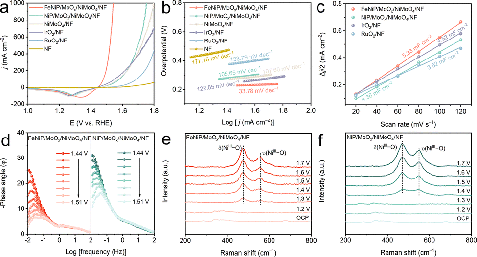 | ||
| Fig. 2 (a) LSV curves and (b) corresponding Tafel plots of FeNiP/MoOx/NiMoO4/NF, NiP/MoOx/NiMoO4/NF, NiMoO4/NF, IrO2/NF, RuO2/NF, and NF in 1 M KOH. (c) Cdl curves and (d) Bode plots. In situ electrochemical Raman spectra for (e) FeNiP/MoOx/NiMoO4/NF and (f) NiP/MoOx/NiMoO4/NF. | ||
To explore the influence of immersion times on OER performance, we conducted a series of experiments. The results reveal that a 5-min immersion time provides the optimal performance for the OER (Fig. S13, ESI†). To thoroughly evaluate the catalytic performance and stability of FeNiP/MoOx/NiMoO4/NF, we investigated its OER activity in alkaline simulated seawater (1 M KOH + 0.5 M NaCl) and alkaline seawater (1 M KOH + seawater; comprehensive details about the seawater used in the experiment are presented in Table S2, ESI†). The catalyst demonstrates similar electrocatalytic performance across three different electrolyte systems (Fig. 3a). It requires a η of 349 mV to achieve 1000 mA cm−2 in alkaline seawater, outperforming NiP/MoOx/NiMoO4/NF, NiMoO4/NF, IrO2/NF, and RuO2/NF (Fig. S14, ESI†). Notably, it exhibits exceptional performance compared to most reported ASO catalysts (Table S3, ESI†). As shown in Fig. 3b and Fig. S15 (ESI†), the catalyst exhibits superior intrinsic activity with a turnover frequency of 2.95 s−1 at 350 mV, which is higher than that of NiP/MoOx/NiMoO4/NF (0.25 s−1), IrO2/NF (0.37 s−1), and RuO2/NF (0.39 s−1). Furthermore, the activation energy (Ea) for the OER was determined (Fig. 3c). FeNiP/MoOx/NiMoO4/NF shows a significantly lower Ea of 28.44 kJ mol−1 compared to NiP/MoOx/NiMoO4/NF (36.83 kJ mol−1). This enhancement is directly correlated with the improved OER activity.
 | ||
| Fig. 3 (a) LSV curves and corresponding η comparison of FeNiP/MoOx/NiMoO4/NF in different electrolytes. (b) TOF plots and (c) LSV curves of FeNiP/MoOx/NiMoO4/NF and NiP/MoOx/NiMoO4/NF at different temperatures and Arrhenius plots in 1 M KOH + seawater. (d) Chronopotentiometry curves of FeNiP/MoOx/NiMoO4/NF and NiMoO4/NF. (e) UV-vis absorption spectra of electrolytes after the stability test. (f) Corrosion polarization curves (inset: corresponding corrosion potentials and currents). In situ Raman spectra for (g) FeNiP/MoOx/NiMoO4/NF and (h) NiMoO4/NF during the ASO process. | ||
To evaluate the long-term electrochemical stability of the catalysts, we performed chronopotentiometric measurements on FeNiP/MoOx/NiMoO4/NF and NiMoO4/NF at 1000 mA cm−2. The results in Fig. 3d reveal that FeNiP/MoOx/NiMoO4/NF maintains stable operation for 500 h, outperforming NiMoO4/NF (100 h degradation). Quantitative analysis of Mo, Fe, and P dissolution was performed via inductively coupled plasma optical emission spectrometry (ICP-OES) following extended chronopotentiometric testing (100 h, j = 1000 mA cm−2). The FeNiP/MoOx/NiMoO4/NF electrode exhibits markedly reduced Mo leaching (37.09 mg L−1), Fe leaching (0.038 mg L−1), and P leaching (15.68 mg L−1), confirming its superior structural stability (Table S4, ESI†). Post-stability SEM analysis reveals that the morphology of FeNiP/MoOx/NiMoO4/NF remains almost unchanged after the stability test (Fig. S16, ESI†). To assess the corrosion resistance of the catalysts, we quantified active chlorine species following stability testing (Fig. S17, ESI†). The ultraviolet–visible (UV–vis) spectra indicate that the FeNiP/MoOx/NiMoO4/NF produces a lower concentration of active chlorine after the stability test compared to NiMoO4/NF (Fig. 3e). In addition, it demonstrates superior corrosion resistance with a higher potential (365 mV) and lower current (0.024 mA) than NiMoO4/NF (Fig. 3f). These results are attributed to the synergistic protective effects of PO43− and MoO42− generated during electrolysis that effectively repel Cl− than NiMoO4/NF alone. In situ Raman spectra provide mechanistic insights. The Raman spectra of the two catalysts at OCP reveal characteristic NiMoO4 vibrations at 800–1000 cm−1 (Fig. 3g and h). As the potential increased, the characteristic Raman modes of NiMoO4 progressively diminish in intensity. Notably, the emergence of two distinct vibrational bands at 900 and 980 cm−1 is assigned to surface-adsorbed MoO42− and PO43−, respectively.33,34 In contrast to the FeNiP/MoOx/NiMoO4/NF, NiMoO4/NF only detects MoO42−. This result confirms that phosphidation treatment establishes an additional protective surface layer of PO43− to repel Cl−, thereby enhancing the catalyst's stability during the ASO process.
The practical feasibility of FeNiP/MoOx/NiMoO4/NF was demonstrated in an anion-exchange membrane (AEM) electrolyzer system with an asymmetric electrolyte feed configuration (Fig. 4a). When paired with a Pt/C/NF cathode, the FeNiP/MoOx/NiMoO4/NF anode achieves remarkable performance, achieving 500 mA cm−2 at just 2.43 V compared to Pt/C/NF‖RuO2/NF (500 mA cm−2 at 2.99 V), and maintaining stable operation at 300 mA cm−2 for 180 h (Fig. 4b–d). This result confirms that FeNiP/MoOx/NiMoO4/NF significantly enhances both efficiency and operational stability in practical electrolysis applications.
 | ||
| Fig. 4 (a) Schematic diagram of AEM-based electrolysis with an asymmetric alkaline seawater supply. (b) Polarization curves. (c) Cell voltages required for the two pairs of electrodes to achieve different j. (d) The chronopotentiometry curve of the Pt/C/NF‖FeNiP/MoOx/NiMoO4/NF tested in 1 M KOH + seawater. | ||
In conclusion, FeNiP/MoOx/NiMoO4/NF is demonstrated as an efficient and stable anode for ASO electrocatalysis. The FeNiP/MoOx/NiMoO4/NF achieves 1000 mA cm−2 at a low η of 349 mV and maintains remarkable stability for 500 h at this industrial-level j. Notably, Pt/C/NF‖FeNiP/MoOx/NiMoO4/NF operates at a low cell voltage of 2.12 V to deliver 300 mA cm−2 while demonstrating exceptional stability for 180 h. The remarkable stability of the electrocatalyst originates from in situ generated PO43− and MoO42− during the ASO process, which electrostatically repel Cl− and significantly enhance corrosion resistance. This work not only presents an earth-abundant catalyst for efficient and stable seawater oxidation, but would open up an exciting new avenue for designing Cl−-repelling catalysts through the synergistic integration of elemental doping and anion repulsion.
The authors extend their appreciation to the Deanship of Research and Graduate Studies at King Khalid University for funding this work through the Large Research Project under Grant number RGP2/28/46.
Conflicts of interest
There are no conflicts to declare.Data availability
Data presented in this work are available within the article and/or its ESI,† and upon request to the authors.References
- J. A. Turner, Science, 2004, 305, 972–974 CrossRef CAS PubMed
.
- R. Zhang, A. Xie, L. Cheng, Z. Bai, Y. Tang and P. Wan, Chem. Commun., 2023, 59, 8205–8221 RSC
- A. Goldthau, Nature, 2017, 546, 203–205 CrossRef CAS PubMed
- J. Wang, Q. Liu, W. Cui, Z. Xing, A. M. Asiri and X. Sun, Adv. Mater., 2016, 28, 215–230 CrossRef CAS PubMed
- T. Wei, W. Liu, S. Zhang, Q. Liu, J. Luo and X. Liu, Chem. Commun., 2023, 59, 442–445 RSC
- C. J. Vörösmarty, P. B. McIntyre, M. O. Gessner, D. Dudgeon, A. Prusevich, P. Green, S. Glidden, S. E. Bunn, C. A. Sullivan, C. R. Liermann and P. M. Davies, Nature, 2010, 467, 555–561 CrossRef PubMed
- J. Liang, Z. Cai, X. He, Y. Luo, D. Zheng, S. Sun, Q. Liu, L. Li, W. Chu, S. Alfaifi, F. Luo, Y. Yao, B. Tang and X. Sun, Chemistry, 2024, 10, 3067–3087 CrossRef CAS
- J. Liang, J. Li, H. Dong, Z. Li, X. He, Y. Wang, Y. Yao, Y. Ren, S. Sun, Y. Luo, D. Zheng, J. Li, Q. Liu, F. Luo, T. Wu, G. Chen, X. Sun and B. Tang, Nat. Commun., 2024, 15, 6208 CrossRef CAS PubMed
- Q. Sha, S. Wang, L. Yan, Y. Feng, Z. Zhang, S. Li, X. Guo, T. Li, H. Li, Z. Zhuang, D. Zhou, B. Liu and X. Sun, Nature, 2025, 639, 360–367 CrossRef CAS PubMed
- T. Wang, Y. Yuan, W. Shi, G. Li, P. Rao, J. Li, Z. Kang and X. Tian, Chem. Commun., 2025, 61, 1719–1728 RSC
- J. Liang, Z. Cai, Z. Li, M. Geng, H. Wang, Z. Wang, T. Li, T. Wu, F. Luo, X. Sun and B. Tang, ACS Nano, 2025, 19, 1530–1546 CrossRef CAS PubMed
- J. Liu, S. Duan, H. Shi, T. Wang, X. Yang, Y. Huang, G. Wu and Q. Li, Angew. Chem., Int. Ed., 2022, 61, e202210753 CrossRef CAS PubMed
- Z. Cai, J. Liang, Z. Li, T. Yan, C. Yang, S. Sun, M. Yue, X. Liu, T. Xie, Y. Wang, T. Li, Y. Luo, D. Zheng, Q. Liu, J. Zhao, X. Sun and B. Tang, Nat. Commun., 2024, 15, 6624 CrossRef CAS PubMed
- X. He, Y. Yao, L. Zhang, H. Wang, H. Tang, W. Jiang, Y. Ren, J. Nan, Y. Luo, T. Wu, F. Luo, B. Tang and X. Sun, Nat. Commun., 2025, 16, 4998 CrossRef PubMed
- S. Khatun, S. Pal, N. Sinha, C. Das, T. Ahmed and P. Roy, Chem. Commun., 2023, 59, 4578–4599 RSC
- X. He, Y. Yao, M. Zhang, Y. Zhou, L. Zhang, Y. Ren, K. Dong, H. Tang, J. Nan, X. Zhou, H. Luo, B. Ying, Q. Yu, F. Luo, B. Tang and X. Sun, Nat. Commun., 2025, 16, 5541 CrossRef PubMed
- C. Yang, L. Bi, Z. Cai, Z. Li, S. Sun, X. Wang, M. Zhang, M. Yue, D. Zheng, Y. Luo, M. S. Hamdy, A. Farouk, Y. Yao, X. Sun and B. Tang, ACS Mater. Lett., 2024, 6, 5248–5255 CrossRef CAS
- C. Lan, H. Xie, Y. Wu, B. Chen and T. Liu, Energy Fuels, 2022, 36, 2910–2917 CrossRef CAS
- X. He, Y. Cheng, Q. Zhang, T. Yan, K. Dong, Y. Yao, J. Nan, Y. Zhou, X. Guo, D. Zheng, S. Sun, J. Zhao, B. Ying, F. Luo, B. Tang and X. Sun, Nano Today, 2024, 58, 102454 CrossRef CAS
- X. Kang, F. Yang, Z. Zhang, H. Liu, S. Ge, S. Hu, S. Li, Y. Luo, Q. Yu, Z. Liu, Q. Wang, W. Ren, C. Sun, H. M. Cheng and B. Liu, Nat. Commun., 2023, 14, 3607 CrossRef CAS PubMed
- X. Guo, X. He, X. Liu, S. Sun, H. Sun, K. Dong, T. Li, Y. Yao, T. Xie, D. Zheng, Y. Luo, J. Chen, Q. Liu, L. Li, W. Chu, Z. Jiang, X. Sun and B. Tang, Small, 2024, 20, 2400141 CrossRef CAS PubMed
- D. Zhang, Y. Wang, X. Du and X. Zhang, Int. J. Hydrogen Energy, 2024, 49, 1387–1398 CrossRef CAS
- Y. Guo, E. Liu, Y. Li and R. Song, Chem. Eng. J., 2025, 511, 162132 CrossRef CAS
- A. Rajput, M. K. Adak and B. Chakraborty, Inorg. Chem., 2022, 61, 11189–11206 CrossRef CAS PubMed
- Z. Li, W. Zuo, C. Liu, C. Yang, Z. Cai, S. Sun, M. Yue, M. Zhang, X. Wang, H. Wang, D. Zheng, A. Farouk, F. A. Ibrahim, F. Gong, Y. Lv, X. Sun and B. Tang, Small, 2025, 21, 2408642 CrossRef CAS PubMed
- L. Wu, L. Yu, F. Zhang, B. McElhenny, D. Luo, A. Karim, S. Chen and Z. Ren, Adv. Funct. Mater., 2021, 31, 2006484 CrossRef CAS
- M. Li, H. Li, X. Jiang, M. Jiang, X. Zhan, G. Fu, J. M. Lee and Y. Tang, J. Mater. Chem. A, 2021, 9, 2999–3006 RSC
- Y. Wang, P. Yang, Y. Gong, D. Liu, S. Liu, W. Xiao, Z. Xiao, Z. Li, Z. Wu and L. Wang, Chem. Eng. J., 2023, 468, 143833 CrossRef CAS
- S. Ge, P. Cheng, Y. Zhao, H. Jin, Y. Su, N. Li, J. Li, Z. Xiong, C. Feng and D. Shi, Small, 2025, 21, 2406578 CrossRef CAS PubMed
- Y. Li, H. Zhang, M. Jiang, Q. Zhang, P. He and X. Sun, Adv. Funct. Mater., 2017, 27, 1702513 CrossRef
- H. Hao, Y. Li, Y. Wu, Z. Wang, M. Yuan, J. Miao, Z. Lv, L. Xu and B. Wei, Mater. Today Energy, 2022, 23, 100887 CrossRef CAS
- R. N. Dürr, P. Maltoni, H. Tian, B. Jousselme, L. Hammarström and T. Edvinsson, ACS Nano, 2021, 15, 13504–13515 CrossRef PubMed
- J. Zhou, L. Liu, H. Ren, L. Li, W. Song, N. Li, X. Shi, C. Kou, Y. Sun, M. Han, H. Wang, J. Han, K. Liu, C. D. Momo, Y. Liu, D. Feng, W. Zhu, S. Chen, H. Jiang, Y. Liu and H. Liang, Inorg. Chem. Front., 2024, 11, 498–507 RSC
- C. Yang, Z. Cai, J. Liang, K. Dong, Z. Li, H. Sun, S. Sun, D. Zheng, H. Zhang, Y. Luo, Y. Yao, Y. Wang, Y. Ren, Q. Liu, L. Li, W. Chu, X. Sun and B. Tang, Nano Res., 2024, 17, 5786–5794 CrossRef CAS
Footnotes |
| † Electronic supplementary information (ESI) available: Experimental section and supplementary figures. See DOI: https://doi.org/10.1039/d5cc02784e |
| ‡ Both authors contributed equally to this work. |
| This journal is © The Royal Society of Chemistry 2025 |